Page 825 of 1146
PARKING BRAKES - Parking Brake36-9
4WD>
190Nm
137ft.lbs.
83Nm12 Nm60ft.lbs.9 ft.lbs.50-60
Nm36 43-ft.lbs.Removal steps
+*I. Rear speed sensor2. O-ring
3. Rear brake assembly
4. Rear brake disc
50-60Nm36 - 43 ft.lbs.l * l *9. Self-locking nut10. Companion flangel *11. Rear axle shaft
12. Adjusting wheel spring
13. Shoe hold-down
CUD14. Shoe hold-down spnng15. Shoe hold-down pinI)* 16. AdjusterI)* 17. Shoe-to-anchor spring
18. Strut
19. Strut return spring
20. Shoe
& lining assembly
21. Clip
22. Brake tube connection
23. Backing plate23
Grease: Brake grease SAE 5310, NLGI No. 1
1 TSB Revision1
Page 826 of 1146

36-10PARKING BRAKES - Parking Brake
SERVICE POINTS OF REMOVALM36YBALI. REMOVAL OF REAR SPEED SENSOR
Caution
When removing the speed sensor from the knuckle, usei&J 1
care not to hit the pole piece at its tip against the rotorteeth or other parts.
11 FO03814LOOOi
14NOli9. REMOVAL OF SELF-LOCKING NUT
With the special tool, secure the axle shaft and remove the
companion flange self-locking nut.
II. REMOVAL OF AXLE SHAFT ASSEMBLY
With the special tool, remove the axle shaft from the trailing
arm.
INSPECTIONM36YCAI
CHECKING FOR UNUSUAL WEAR OF THE BRAKE LININGAND BRAKE DRUM
(1) Measure the thickness of the brake lining at several places.
Standard value: 2.8 mm
(.I10 in.)
Limit:
1.0 mm (.039 in.)
Caution
Replace the brake shoes if the thickness of the brakelining is the limit value or less.
(2)Measure the brake disc drum inner diameter at two or more
places.Standard value: 168.0 mm (6.6 in.)
Limit: 169.0 mm (6.7 in.)
CautionReplace if the brake disc drum inner diameter is the
limit value or more.
TSB Revision
Page 827 of 1146

PARKING BRAKES - Parking Brake36-11
14N000'
Spindle,
I’_14NOO05
SERVICE POINTS OF INSTALLATIONM36YDAP
17. INSTALLATION OF SHOE-TO-ANCHOR SPRINGThe shoe-to-anchor spring must be installed in the se-
quence shown in the illustration.
Caution
Each shoe-to-anchor spring has a unique spring loadand the spring “a”is painted to prevent erroneous
installation.
NOTEThe figure shows the left wheel; for the right wheel, the
position in symmetrical.
16. INSTALLATION OF ADJUSTERInstall the adjuster facing the left adjusting bolt to the
vehicle front and right adjusting bolt to the vehicle rear.
9. INSTALLATION OF SELF-LOCKING NUT
With the special tool, secure the axle shaft and tighten the
companion flange self-locking nut.
6. INSTALLATION OF FLANGE NUT
After tightening the flange nut, align with the spindle’s
indentation and crimp.
1. INSTALLATION OF REAR SPEED SENSOR
Insert a filler gauge between the speed sensor pole piece
and rotor teeth and tighten the speed sensor at such
position where the gap is as specified below over the entire
circumference.
Standard value: 0.2
- 0.7 mm (.008 - .028 in.)
TSB Revision
Page 940 of 1146

51-2
SPECIFICATIONSEXTERIOR
- Specifications
GENERAL SPECIFICATIONSMSlKB-
-\ IItems
Windshield wiper motorType
Speed control system
Braking system
rpm at load of 1 Nm (0.72
ft.lbs.)Low speed
High speed
Nominal torque
Nm (ft.lbs.)
Rear wiper motor
Motor type
Braking system
rpm at load of 0.6 Nm (0.43
ft.lbs.)Windshield wiper blade
Wiping angle
Driver’s side
Passenger’s side
Wiper blade length
mm (in.)
Driver’s side
Passenger’s side
Tear wiper blade
Wiping angle
Wiper blade lengthmm (in.)
Nindow washer motor and pump
Motor type
Pump type
Power consumption A
Time of continuous usesec.
With washer fluid
Empty operation
Nozzle jet pressure
kPa (psi)
Tank capacity
lit.
(qts.)
3ear window washer motor and pump
Motor type
Pump type
Power consumption A
Time of continuous use
sec.With washer fluid
Empty operation
Nozzle jet pressure
kPa (psi)
Tank capacity
lit. (qts.)Specifications
Ferrite-magnet type
Third brush system
Dynamic brake system
48
_+ 4
70
2 724(17)
Ferrite-magnet type
Dynamic braking system
38
+ 5
89”
91”
525 (20.7)
500 (19.7)87”
k 1.5”
550 (21.7)Direct current ferrite magnet type
Centrifugal type
3.8 or less
Max. 60
Max. 20
120 (17) or more
2.0
(2.1) or more
Direct current ferrite magnet type
Centrifugal type
3.8 or less
Max. 60
Max. 20
120 (17) or more
1.2 (1.3) or more
LJ
L/iTSB Revision
Page 1110 of 1146

55-28HEATERS AND MANUAL AIR CONDITIONER - Comtxessor
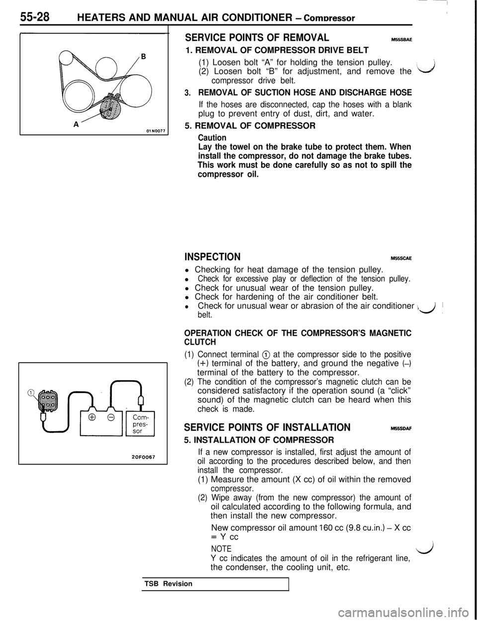
20F0067
SERVICE POINTS OF REMOVALM55SBAE1. REMOVAL OF COMPRESSOR DRIVE BELT
(1) Loosen bolt “A” for holding the tension pulley.
(2) Loosen bolt “B” for adjustment, and remove the
‘J
compressor drive belt.
3.REMOVAL OF SUCTION HOSE AND DISCHARGE HOSE
If the hoses are disconnected, cap the hoses with a blankplug to prevent entry of dust, dirt, and water.
5. REMOVAL OF COMPRESSOR
Caution
Lay the towel on the brake tube to protect them. When
install the compressor, do not damage the brake tubes.
This work must be done carefully so as not to spill the
compressor oil.
INSPECTIONM55SCAEl Checking for heat damage of the tension pulley.
l
Check for excessive play or deflection of the tension pulley.l Check for unusual wear of the tension pulley.
l Check for hardening of the air conditioner belt.
lCheck for unusual wear or abrasion of the air conditioner ,
belt.
\d’
OPERATION CHECK OF THE COMPRESSOR’S MAGNETIC
CLUTCH
(1) Connect terminal @ at the compressor side to the positive
(+) terminal of the battery, and ground the negative (-)terminal of the battery to the compressor.
(2) The condition of the compressor’s magnetic clutch can beconsidered satisfactory if the operation sound (a “click”
sound) of the magnetic clutch can be heard when this
check is made.
SERVICE POINTS OF INSTALLATIONM55SDAF5. INSTALLATION OF COMPRESSOR
If a new compressor is installed, first adjust the amount of
oil according to the procedures described below, and then
install the compressor.(1) Measure the amount (X cc) of oil within the removed
compressor.
(2) Wipe away (from the new compressor) the amount ofoil calculated according to the following formula, and
then install the new compressor.
New compressor oil amount
160 cc (9.8 cu.in.) - X cc= Y cc
NOTE
Y cc indicates the amount of oil in the refrigerant line,l/jthe condenser, the cooling unit, etc.
TSB Revision