Page 874 of 1146

42-2BODY - SDecifications
SPECIFICATIONS
GENERAL SPECIFICATIONS
M42CA. -
Items
Hood
Type
Specifications
Rear hinged, front
opening type (with gas damper)
Door
Construction
Regulator system
Locking system
Liftgate
Type
Front-hinged, sashless
Wire type
Pin-fork type
Inner-hinged, with gas damper
Glass installation method
Windshield glassAdhesive type
Quarter window glassAdhesive type
Liftgate window glassAdhesive type
Glass thicknessmm (in.)
Windshield glass5.3 (.21)
Liftgate window glass3.5 (.I41
Door glass5.0 f.20)
Quarter window glass3.5 (.14)
Power window motor
TypePermanent magnet type (Built-in circuit breaker)
Revolutions under no load
rpm75 or more
Revolutions under load
vm
At 1 Nm (.72 ft.lbs.145-75
At 2 Nm (1.45 ft.lbs.)50-80
Bound current A
34 or less
Direction of rotationClockwise and counter-clockwise
Power window main switch
TypeAutomatic reset type
Rated load currentA
Lock switch
10Power window switch
10
Power window sub switch
TypeAutomatic reset type
Rated load currentA10
Power window relay
Maximum contact current
A20
Rated coil current
AMax. 0.2
Voltage drop between terminals
V0.2 or less
(At 12 V and the rated load current)TSB Revision
Page 1034 of 1146

52B-24 SUPPLEMENTAL RESTRAINT SYSTEM (SRS) - Troubleshooting
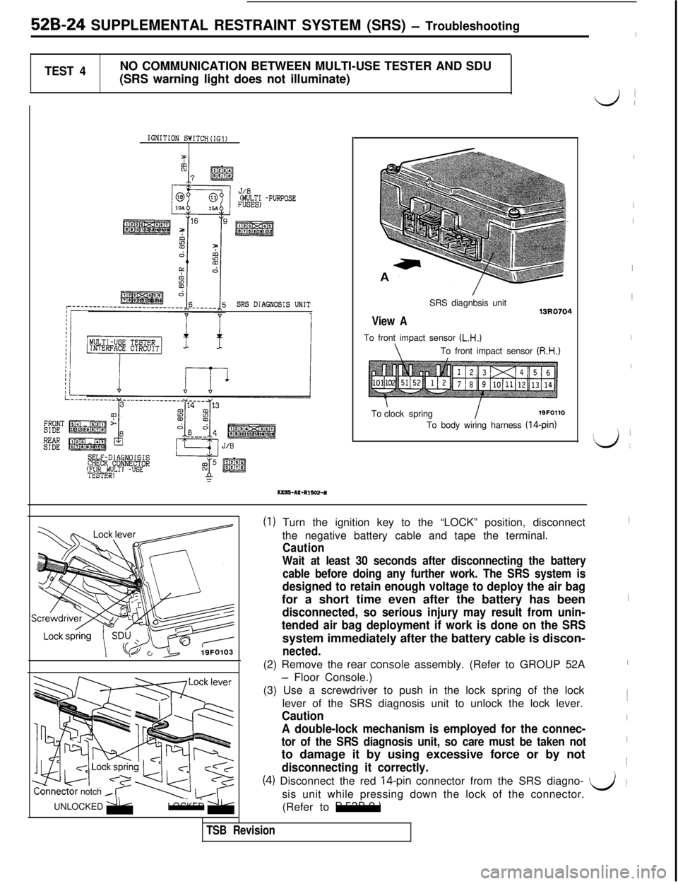
TEST 4NO COMMUNICATION BETWEEN MULTI-USE TESTER AND SDU
(SRS warning light does not illuminate)
IGNITION SWITCH(IG1)
J/.8(MULTI -PURPOSEFUSES)
SRS DIAGNOSIS UNIT
MULTI -3SETESTER1
KKRS-AX-RISE+R
View ASRS diagnbsis unit
To front impact sensor
(L.H.)
\To front impact sensor (R.H.)Toclock spring
I19FOllO
To body wiring harness (14-pin)
onnectornotch -UNLOCKED
;;bb;;,LOCKED zRok
(1) Turn the ignition key to the “LOCK” position, disconnect
the negative battery cable and tape the terminal.
Caution
Wait at least 30 seconds after disconnecting the battery
cable before doing any further work. The SRS system is
designed to retain enough voltage to deploy the air bagfor a short time even after the battery has been
disconnected, so serious injury may result from unin-
tended air bag deployment if work is done on the SRSsystem immediately after the battery cable is discon-
nected.(2) Remove the rear.console assembly. (Refer to GROUP 52A
- Floor Console.)
(3) Use a screwdriver to push in the lock spring of the lock
lever of the SRS diagnosis unit to unlock the lock lever.
Caution
A double-lock mechanism is employed for the connec-
tor of the SRS diagnosis unit, so care must be taken notto damage it by using excessive force or by not
disconnecting it correctly.
idi
I
I
I
I
I
I
I
L)I
I
I
I1
I
I~
i(4) Disconnect the red l4-pin connector from the SRS diagno- L/~
sis unit while pressing down the lock of the connector.
(Refer to
P.52B-9.)
\
TSB Revision
Page 1072 of 1146

52B-62Air Bag ModuleSUPPLEMENTAL RESTRAINT SYSTEM (SRS) - and Clock Spring
AIR BAG MODULE AND CLOCK SPRINGM52PDCA
Caution1. Never attempt to disassemble or repair the
air bag module or clock spring.
If faulty, replace it.
2. Do not drop the air bag module or clock
spring or allow contact with water, grease or
oil.Replace it if a dent, crack, deformation or
rust are detected.
3.The air bag module should be stored on a flat
surface and placed so that the pad surface isfacing upward.
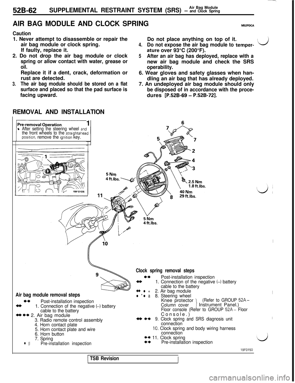
REMOVAL AND INSTALLATION1
l After setting the steering wheel antthe front wheels to the stralghtaheaposltion. remove the ignition key.5NmDo not place anything on top of it.
4.Do not expose the air bag module to temper-ILJ
ature over 93°C (200°F).
5After an air bag has deployed, replace with anew air bag module and check the SRS
operability.6. Wear gloves and safety glasses when han-
dling an air bag that has already deployed.
7. An undeployed air bag module should only
be disposed of in accordance with the proce-dures
[P.52B-69 - P.52B-721.
Air bag module removal stepsI)4
Post-installation inspection4*1. Connection of the negative (-1 battery
cable to the battery
*I) I)* 2. Air bag module3. Radio remote control assembly
4. Horn contact plate
5. Horn contact plate and wire
6. Horn button
7. Spring
l 4Pre-installation inspection
Clock spring removal steps
I)4Post-installation inspection4*1. Connection of the negative (-1 battery
cable to the battery
+* l +2. Air bag modulel * l a8. Steering wheelKnee protector 1(Refer to GROUP 52A-
Column coverJ Instrument Panel.)Floor console (Refer to GROUP 52A- FloorConsole.)
*I) *+9. Clock spring and SRS diagnosis unitconnection10. Clock spring and body wiring harness
connection
I)* 11. Clock springI)4Pre-installation inspection
I1
I
‘d
1 TSB Revision
19FO150
III