1991 LEXUS SC400 coolant level
[x] Cancel search: coolant levelPage 2886 of 4087

The 1 UZ±FE engine has 8±cylinders in a V±arrangement at a bank an\
gle of 905. From the front of the RH
bank cylinders are numbered 2±4±6±8, and from the front of the LH b\
ank cylinders are numbered 1 ±3±5±7.
The crankshaft is supported by 5 bearings specified by the inside of the cr\
ankcase. These bearings are made
of a copper and lead alloy. The crankshaft is integrated with 8 weights which are cast along with it\
for balancing. Oil holes are built
into the center of the crankshaft for supplying oil to the connecting ro\
ds, pistons and other components. The ignition order is 1±8±4±3±6±5±7±2. The cylinder\
head is made of aluminum alloy, with a cross flow
type intake and exhaust layout and with pent±roof type combustion chambers. The spark plugs are loca\
ted in
the center of the combustion chambers.
At the front and rear of the intake manifold, a water passage has been p\
rovided which connects the RH
and LH cylinder heads. Exhaust and intake valves are equipped with irregular pitch springs made\
of special valve spring carbon
steel which are capable of following no matter what the engine speed.
The RH and LH intake camshafts are driven by a single timing belt, and a ge\
ar on the intake camshaft en-
gages with a gear on the exhaust camshaft to drive it. The camshaft jour\
nal is supported at 5 (intake) or 4 (ex-
haust) places between the valve lifters of each cylinder and on the front end of the cylinder \
head. Lubrication
of the cam journal gear is accomplished by oil being supplied through the \
oiler port in the center of the camshaft. Adjustment of the valve clearance is done by means of an outer shim type\
system, in which valve adjusting
shims are located above the valve lifters. This permits replacement of the sh\
ims without removal of the cam-
shafts. Pistons are made of high temperature±resistant aluminum alloy, and a depression is built into the piston
head to prevent interference with valves.
Piston pins are the full±floating type, with the pins fastened to neither the piston boss nor the connecting
rods. Instead, snap rings are fitted on both ends of the pins, preventing the\
pins from falling out. The No.1 compression ring is made of steel and the No.2 compression ring\
is made of cast iron. The oil
ring is m ade of a combination of steel and stainless steel. The outer diameter of\
each piston ring is slightly larger
than the diameter of the piston and the flexibility of the rings allows them\
to hug the cylinder walls when they
are mounted on the piston. Compression rings No.1 and No.2 work to prevent \
the leakage of gas from the cylin-
der and the oil ring works to scrape oil off the cylinder walls to prevent it from entering the combustion chamber. The cylinder block is made of aluminum alloy with a bank angle of 90 5. Cast iron cylinders are installed
inside the cylinder block. It has 8 cylinders which are approximately twice the length of th\
e piston stroke. The
top of each cylinder is closed off by the cylinder heads and the lower end of the cylinders becomes the crank-
case, in which the crankshaft is installed. In addition, the cylinder bl\
ock contains a water jacket, through which
coolant is pumped to cool the cylinders. The No.1 and No.2 oil pans are bolted onto the bottom of the cylinder block\
. The No.1 oil pan is made of
aluminum alloy. The No.2 oil pan is an oil reservoir made of pressed steel sheet. An o\
il level sensor is installed
in the No.1 oil pan (If the oil level drops below a set level, a warnin\
g light lights up.). A oil pan baffle plate keeps
sufficient oil in the bottom of the No.2 oil pan even when the vehicle is tilted. \
This dividing plate also prevents
the oil from making waves when the vehicle is stopped suddenly and the oil \
shifts away from the oil pump suction
pipe. Plastic region tightening bolts are used for the cylinder head, main bearing ca\
p and connecting rod.
EM±4
±
ENGINE MECHANICAL Operation
WhereEverybodyKnowsYourName
Page 3362 of 4087
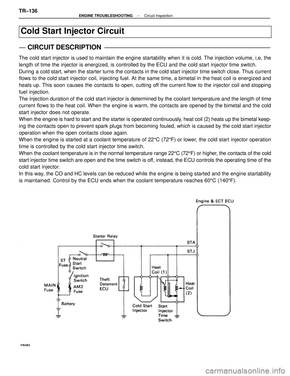
Cold Start Injector Circuit
CIRCUIT DESCRIPTION
The cold start injector is used to maintain the engine startability when it\
is cold. The injection volume, i,e, the
length of time the injector is energized, is controlled by the ECU and t\
he cold start injector time switch.
During a cold start, when the starter turns the contacts in the cold start inj\
ector time switch close. Thus current
flows to the cold start injector coil, injecting fuel. At the same time, a bi\
metal in the heat coil is energized and
heats up. This soon causes the contacts to open, cutting off the current flow to the injector coil and stopping
fuel injection.
The injection duration of the cold start injector is determined by the cool\
ant temperature and the length of time
current flows to the heat coil. When the engine is warm, the contacts are opened by the bimetal and the cold
start injector does not operate.
When the engine is hard to start and the starter is operated continuously, heat coil (2) heats up the bimetal keep-
ing the contacts open to prevent spark plugs from becoming fouled, which is\
caused by the cold start injector
operation when the open contacts close again.
When the engine is started at a coolant temperature of 225C (72 5F) or lower, the cold start injector operation
time is controlled by the cold start injector time switch.
When the coolant temperature is in the normal temperature range 22 5C (72 5F) or higher, the contacts of the cold
start injector time switch are open and the time switch is off, instead, the ECU controls the operating time of the
cold start injector.
In this way, the CO and HC levels can be reduced while the engine is being started \
and the engine startability
is maintained. Control by the ECU ends when the coolant temperature reac\
hes 60 5C (140 5F).
TR±136±
ENGINE TROUBLESHOOTING Circuit Inspection
WhereEverybodyKnowsYourName
Page 3574 of 4087
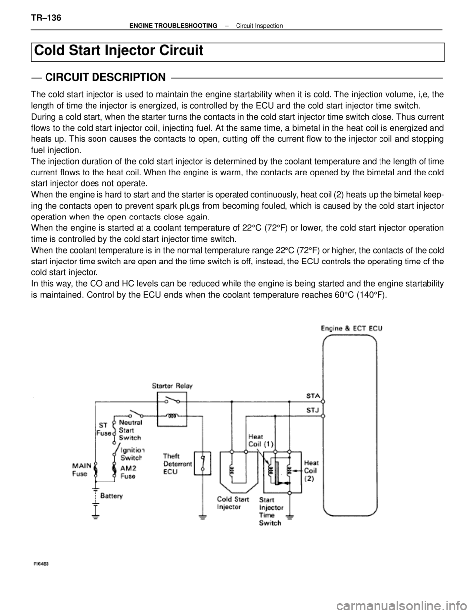
Cold Start Injector Circuit
CIRCUIT DESCRIPTION
The cold start injector is used to maintain the engine startability when it\
is cold. The injection volume, i,e, the
length of time the injector is energized, is controlled by the ECU and t\
he cold start injector time switch.
During a cold start, when the starter turns the contacts in the cold start inj\
ector time switch close. Thus current
flows to the cold start injector coil, injecting fuel. At the same time, a bi\
metal in the heat coil is energized and
heats up. This soon causes the contacts to open, cutting off the current flow to the injector coil and stopping
fuel injection.
The injection duration of the cold start injector is determined by the cool\
ant temperature and the length of time
current flows to the heat coil. When the engine is warm, the contacts are opened by the bimetal and the cold
start injector does not operate.
When the engine is hard to start and the starter is operated continuously, heat coil (2) heats up the bimetal keep-
ing the contacts open to prevent spark plugs from becoming fouled, which is\
caused by the cold start injector
operation when the open contacts close again.
When the engine is started at a coolant temperature of 225C (72 5F) or lower, the cold start injector operation
time is controlled by the cold start injector time switch.
When the coolant temperature is in the normal temperature range 22 5C (72 5F) or higher, the contacts of the cold
start injector time switch are open and the time switch is off, instead, the ECU controls the operating time of the
cold start injector.
In this way, the CO and HC levels can be reduced while the engine is being started \
and the engine startability
is maintained. Control by the ECU ends when the coolant temperature reac\
hes 60 5C (140 5F).
TR±136±
ENGINE TROUBLESHOOTING Circuit Inspection
WhereEverybodyKnowsYourName
Page 3862 of 4087
220
COMBINATION METER*1 : W/ TRACTION CONTROL
* 2 : W/O TRACTION CONTROL
2
1
3D
4 3A
6 1E
11
1B5
IK1
12 IK1 11 IK1 13 IK114
IK2
10
OPEN DOOR
RE AR LIGHT
BRAKE
ECT POWER P
R
N
D
C
11 A
17
C
12 A 1A2A 3A4
A
12 B 8
1 2
2 1
EA
10A
DOME
G±O
W±B
W±B
RR
R
G±O
B
GR
R±B
L
G±W
G±W L
R±B
GR
V±R
R±W
V±R
R±W
B
W±B R±W FROM
NEUTRAL START SW
(
A/T )
CLUTCH S TART SW (
M/T )
FROM A/T INDICATOR SW
FROM POWER SOURCE SYSTEM
(
SEE PAGE 56 )
DIODE
(
FOR PARKING
BRAKE )
PARKING
BRAKE SW
COMBINATION METER
P3 D2
C12
,C13 , C1 4
ABC
2
B
4
G±O
FROM ECT PATTERN
SELECT SW
COOLANT LEVEL
TO INTEGRATION
RELAY
BU1
9 B
11
TO LIGHT FAILURE
SENSOR V±G V±G
V±R IE1
1
IG1 20
A
13
R±WI7
I4
2 1
B
DIODE
(
FOR B RAK E
FLUID LEVEL SW )
D1
IG1
19
3E
2
3C
2
R±W
1BRAKE FLUID
LEVEL SW B1 (*2 ) B
IK2
23
R±W R±W
R±W R±W
( CANADA )
(
USA )
R±W
R±W
( USA )
B
(CA NADA )
( *1 )
WhereEverybodyKnowsYourName
Page 3983 of 4087
OVERALL ELECTRICAL WIRING DIAGRAM
1234
21 LEXUS SC300 (
Cont . ne xt pa ge )
4 ACC
IG1
ST 1
IG2
AM1
3
2
6
11 AM2
1J
7
1B
4 16 IE1
20 IK110 IK2
1IE1
1J
31J 51J821B 2
1E
1E
18
1E 1H1E 2 1E
131B
IG1 20 3D
3A 4
3D
2
3C
6
3A
2
3F
1 2 1 6
3F 5
3C
5
3A
IK16
IK1 7
10 IJ1
IE110
IG118
EB
19 IG1
ED EA 13 IE2 14 IG3 W± R
R
Y
B± O Y± B
V±R V± Y
R± W
L±R
W
R±Y B
V±W V
R
L±R
P± L
R
L±R L±R
P± L
P± L
Y
B±O B±YP±L
W± L
R± W
B
W± B R±W
B
W
W
W±L
W± L W±L
W
W±R
Y±B
V±R
V± Y
R±WV±Y V± R Y±B
W± R
W
W± R
B± O
R±W R± W
B
B
R±W R±W
R±W V±Y
BR
W± B
R±W Y
W±B Y
R4713
21 11
4
12
8
7
9
2
1
2
340A IGSW
100A AM1
120A ALT
60A MAIN
30A INJ
30A AM2
14
9 I15
IGNITION SW
7. 5A I GN
10A GAUGE
15A CIG
10A DOME
15A ECU±B
From ABS ECU
<9±2>
From ABS ECU
< 8±5>
(
* 1 )
(
* 2)
6
BATTERY
F9
FUSE BLOCK
12
O2
OI L P RE SS URE SW
C5
COOLANT LEUEL
WARNING SW E6
ENGI NE OI L L EVEL
WARNING SW
P3
PARKI NG
BRAKE SWD2
DIODE
(f or Par king
Brake )
B1
BRAKE FLUID
LEVEL SW
B
B
R±W R±WR±W
R±W
B
B B
( Canada )
(
Canada )
( US A )
(USA )
(
US A )
(
US A )
(
Canada )
(
Canada )(
Canada )
(
* 2
) (
* 1)
(
US A )(
US A)
(
USA )
R±W
R± W
Fro m Dayt i me
Running Light
Relay< 4±4>
Fr om Cr uise Control
ECU< 16±2> T1 5
TRIP SW AND THEFT DETERRENT
I NDI CA TOR L I GHT
S3
SPEED SENSOR No. 1
From Tr act ion ECU
<8±7>
2
W
12 12 2 54 11 13 *
1: (
w/ Tr action Contr ol )
* 2: (
w/oTractionControl )
Power
Source Combination Meter
R±WL±R
R
4 3
SECURITY
M
H
SET
RESET A/ B
W1
WASHER
LEVEL SW
P± L
L±R
R W± R
From ABS ECU
<8±5>
( * 1)
R
R
10 11 12 13 17 18 19 20 21 12345 6789
14 15 16 12 34 56 78
9 10 1112 13 14 1516 1718
17 18
1 2345 6789 10
23
22
21
20
19
15
14
13
12
11 16
AB C
C12 C13 C14 COMBINATION METER
1 1
23
DE
FUEL SENDER
F1 7 F1 8
Rear side of
c ylinder head LH Fr ont side of
right fender Fr ont s ide of
left f ender
2
1
2 2
1 1
1
B
S HORT CONNE CTOR
1
2 12F
S23
G
S22
7BU1
From Tilt and
Power Telesc opic
ECU< 11±2>
GR
B
( M/T ) 3
G±B
From Theft Det err ent and
Door Lock ECU< 17±2>
WhereEverybodyKnowsYourName
Page 3984 of 4087
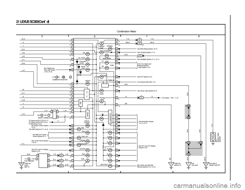
567 8
21 LEXUS SC300(
Cont ' d )
AIR BAG
CHA RGE
OIL
OIL LEVEL COOLANT
LEVEL REAR
LI GHT
PWR
ABS TRAC
TRAC OFF
CRUISE WASHER
O/ D OFF
FUEL
SEAT BELTP
R N D 2 L
A
C
C A
A
B
B
B
C
C
C
C
C
C
C
B C
C
B
B
BA
B
A
A
C
CA A A A A A A A
C
C
C
C C C A C C B B B B
B A A C C
10 : 00
BK 1E
18 3D
10
3A
1
1J
1 1K
12
IH IF ED
IK1
8
IK2 IK1
9
1
E
3
E
2
E
1
D
BU110
BU1
3
BU1
4 11
11
1
14
19
8
18
11
13 6
18
17
16
20
19
15
13
3
15 5
1
20 9
18 8
11
87 1 2 3 4 5 16 17
2
3
4
5 10 9
12 23 12 4 17 16 7
6
15
10 22 21
W± R
RY
B±O
Y±B
V± R
V±Y
R±W
L±R
W
R± Y B
V±W V
R
L±R
P±L
Y±B
B±Y
B± W
W±B BR
B
W± B W± B BR±B
Y± G
B
Y±G
BR±B
W± B
W±B
W±B
BR±B W± B BR
Y±G
WATER
TEMP.HI GH BEAM TURN
LH
RH
BRAKE DOOR
TACHO
TRI P
SPEED
ILLUMINATIONCHECK±
ENGINE
FUEL
See Taillight and
St op Light Sy stem
<4±6><5±6>
SeeEngineControlSystem
<2±3>
Se e ABS Sy st e m< 8± 7> < 9± 3>
See Cruise Control System
< 16±3>Se e ABS an d Tr act io n
Control System< 8±7>
SeeECTandA/TIndicator
System< 3±5>
D
F1 7 , F18 E
FUEL SENDER Y±B
B±Y
B±W 24
See SRS Airbag System< 15±4>
See Charging Sy stem< 1±2>
See Headlight Sys tem< 4±1> < 5±1>
See Turn Signal and
Hazard Warning
Light Sy stem< 7±3>
See ECT System< 3±5>
From Neutr al St art SW< 1±3>
See Interier Light System< 6±3> From Igniter º TACº < 1±5>
To Engine and ECT ECU< 2±7>
To Cruise Control ECU< 16±3>
To PPS ECU< 15±2> See Illumination System
<4±7><5±7>
See ECT and A/T Indic ator
Syst em< 3±6>
See Unlock and Seat Belt
Warning Syst em< 4±4> < 5±4>
W3
WATER TEMP.
SENDER
Combination Meter
1
COMBINATION METER C12 , C13 , C14
A
AB IG1
8
Under the
c ent er
pillar LH Under the
as htr ay LH
Lef t
kick panelRear side of
c ylinder head RH
C
2
G 2
F
1
F 14
L±R
P
P
SH OR T C ON NE CT OR
S2 2 G , S23 F L±R
WhereEverybodyKnowsYourName
Page 3994 of 4087
![LEXUS SC400 1991 Service Repair Manual
47
216182
216
178
216
129 104 144 10260
90
216 62
68
11 2
148
104
111 200 148 148 190
D1
C16 C24
C15 C19 C23 C22
C12
C13
C14C14
C13
C12
Airbag W arning Light
Charge Warning Light
Dimmer SW [Comb. SW] LEXUS SC400 1991 Service Repair Manual
47
216182
216
178
216
129 104 144 10260
90
216 62
68
11 2
148
104
111 200 148 148 190
D1
C16 C24
C15 C19 C23 C22
C12
C13
C14C14
C13
C12
Airbag W arning Light
Charge Warning Light
Dimmer SW [Comb. SW]](/manual-img/36/57051/w960_57051-3993.png)
47
216182
216
178
216
129 104 144 10260
90
216 62
68
11 2
148
104
111 200 148 148 190
D1
C16 C24
C15 C19 C23 C22
C12
C13
C14C14
C13
C12
Airbag W arning Light
Charge Warning Light
Dimmer SW [Comb. SW]Cruise Control Indicator Light
[Comb. Meter]A/T Indicator Light
[Comb. Meter]
Combination Meter
Rear Lights Warning Light Turn Signal Indicator Light
[Comb. Meter] High Beam Indicator Light
[Comb. Meter]
Check Engine Warning Light
Open Door Warning Light
Traction Indicator Light
ABS Warning Light
[Comb. Meter] Seat Belt Warning LightABS Warning Light and T raction
Off Indicator Light [Comb. Meter]
Coolant Level Warning LightCruise Control ECU Turn Signal SW
[Comb. SW]
Wiper and Washer SW
[Comb. SW]
Choke Coil
Crutch Start SW
Cruise Control Clutch SW
Diode (for Brake Fluid Level)Light Control SW
[Comb. SW] Horn SW [Comb. SW]Combination MeterCornering Light SW
[Comb. SW]
C12 80
82
216
216 216 98
86
216134
216
216 216 184
216
80
90
102 80
90
102
68
94
134
148
216
(4)
: R/B No. 5 (See page ) 22
WhereEverybodyKnowsYourName