Page 3748 of 4087

WIRING DIAGRAM
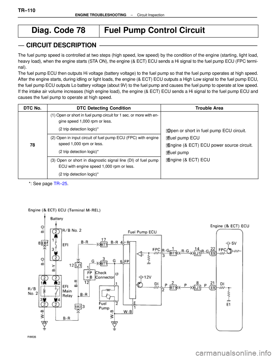
Diag. Code 78Fuel Pump Control Circuit
CIRCUIT DESCRIPTION
The fuel pump speed is controlled at two steps (high speed, low speed) by\
the condition of the engine (starting, light load,
heavy load), when the engine starts (STA ON), the engine (& ECT) ECU sends a Hi signal to the fuel pump ECU \
(FPC termi-
nal).
The fuel pump ECU then outputs Hi voltage (battery voltage) to the fue\
l pump so that the fuel pump operates at high speed.
After the engine starts, during idling or light loads, the engine (& ECT) EC\
U outputs a High Low signal to the fuel pump ECU,
the fuel pump ECU outputs Lo battery voltage (about 9V) to the fuel pu\
mp and causes the fuel pump to operate at low speed.
If the intake air volume increases (high engine load), the engine (& EC\
T) ECU sends a Hi signal to the fuel pump ECU and
causes the fuel pump to operate at high speed.
DTC No.
DTC Detecting ConditionTrouble Area
(1) Open or short in fuel pump circuit for 1 sec. or more with en- gine speed 1,000 rpm or less.
(2 trip detection logic)*
�Open or short in fuel pump ECU circuit.
78
(2) Open in input circuit of fuel pump ECU (FPC) with engine
speed 1,000 rpm or less.
(2 trip detection logic)*�Fuel pump ECU
� Engine (& ECT) ECU power source circuit.
� Fuel pump
(3) Open or short in diagnostic signal line (DI) of fuel pump
ECU with engine speed 1,000 rpm or less.
(2 trip detection logic)*�Engine (& ECT) ECU
*: See page TR±25.
TR±110±
ENGINE TROUBLESHOOTING Circuit Inspection
WhereEverybodyKnowsYourName
Page 3752 of 4087

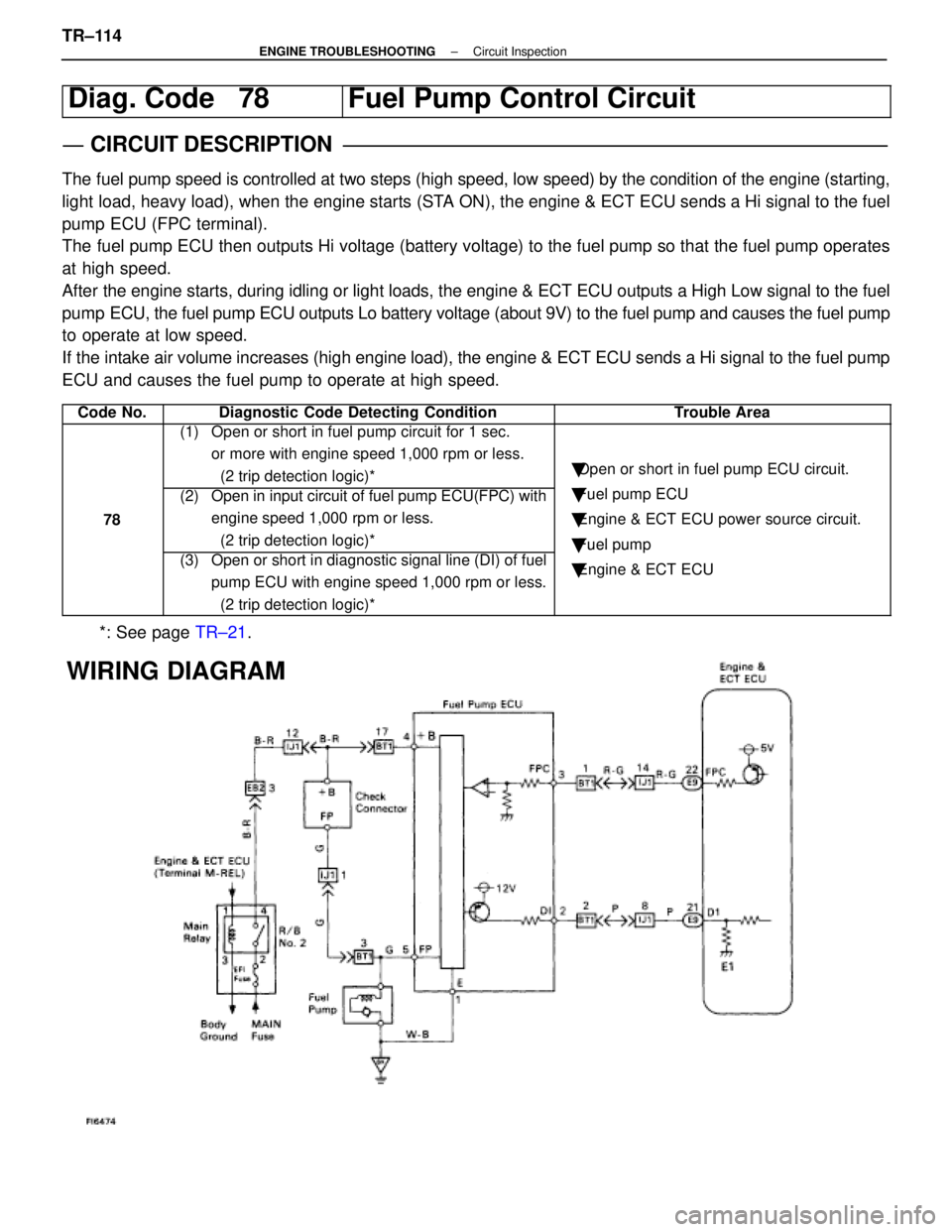
Diag. Code 78Fuel Pump Control Circuit
CIRCUIT DESCRIPTION
The fuel pump speed is controlled at two steps (high speed, low speed) by\
the condition of the engine (starting,
light load, heavy load), when the engine starts (STA ON), the engine & ECT ECU sends a Hi signal to the fuel
pump ECU (FPC terminal).
The fuel pump ECU then outputs Hi voltage (battery voltage) to the fuel p\
ump so that the fuel pump operates
at high speed.
After the engine starts, during idling or light loads, the engine & ECT ECU o\
utputs a High Low signal to the fuel
pump ECU, the fuel pump ECU outputs Lo battery voltage (about 9V) to the f\
uel pump and causes the fuel pump
to operate at low speed.
If the intake air volume increases (high engine load), the engine & ECT \
ECU sends a Hi signal to the fuel pump
ECU and causes the fuel pump to operate at high speed.
Code No.Diagnostic Code Detecting ConditionTrouble Area
(1) Open or short in fuel pump circuit for 1 sec. or more with engine speed 1,000 rpm or less.
(2 trip detection logic)*
�Open or short in fuel pump ECU circuit.
78
(2) Open in input circuit of fuel pump ECU(FPC) with
engine speed 1,000 rpm or less.
(2 trip detection logic)*�Fuel pump ECU
� Engine & ECT ECU power source circuit.
� Fuel pump
(3) Open or short in diagnostic signal line (DI) of fuel
pump ECU with engine speed 1,000 rpm or less.
(2 trip detection logic)*
�Fuel um
�Engine & ECT ECU
*: See page TR±21.
WIRING DIAGRAM
TR±114±
ENGINE TROUBLESHOOTING Circuit Inspection
WhereEverybodyKnowsYourName
Page 3756 of 4087

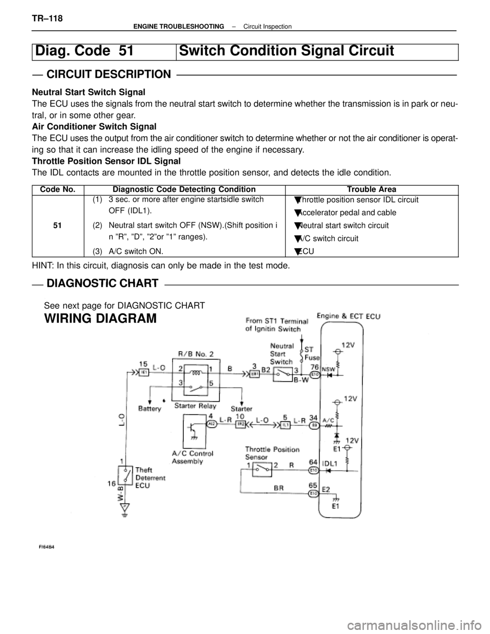
Diag. Code 51Switch Condition Signal Circuit
CIRCUIT DESCRIPTION
Neutral Start Switch Signal
The ECU uses the signals from the neutral start switch to determine whether\
the transmission is in park or neu-
tral, or in some other gear.
Air Conditioner Switch Signal
The ECU uses the output from the air conditioner switch to determine whethe\
r or not the air conditioner is operat-
ing so that it can increase the idling speed of the engine if necessary.
Throttle Position Sensor IDL Signal
The IDL contacts are mounted in the throttle position sensor, and detects the idle condition.
Code No.Diagnostic Code Detecting ConditionTrouble Area
51
(1) 3 sec. or more after engine startsidle switch OFF (IDL1).
(2) Neutral start switch OFF (NSW).(Shift position i n ºRº, ºDº, º2ºor º1º ranges).
(3) A/C switch ON.� Throttle position sensor IDL circuit
� Accelerator pedal and cable
� Neutral start switch circuit
� A/C switch circuit
� ECU
HINT: In this circuit, diagnosis can only be made in the test mode.
DIAGNOSTIC CHARTDIAGNOSTIC CHART
See next page for DIAGNOSTIC CHART
WIRING DIAGRAM
TR±118±
ENGINE TROUBLESHOOTING Circuit Inspection
WhereEverybodyKnowsYourName
Page 3760 of 4087
ECU Power Source Circuit
CIRCUIT DESCRIPTION
When the ignition switch is turned on, battery voltage
is applied to the terminal IGSW of the ECU, and the
main relay control circuit in the ECU sends a signal to
the terminal M±REL of the ECU, switching on the
main relay. This signal causes current to flow to the
coil, closing the contacts of the main relay and supply-
ing power to the terminals +B and +B1 of the ECU.
If the ignition switch is turned off, the ECU continues
to switch on the main relay for a maximum of 2 se-
conds for the initial setting of the ISC valve.
DIAGNOSTIC CHART
See next page for the DIAGNOSTIC CHART.
WIRING DIAGRAM
TR±120±
ENGINE TROUBLESHOOTING Circuit Inspection
WhereEverybodyKnowsYourName
Page 3763 of 4087
OKNG
OKNG
4Check IGN fuse.
C
OK
PRemove IGN fuse from J/B No. 1.
Check continuity of IGN fuse.
Continuity
Check for short in all the harness and components con-
nected to IGN fuse (See attached wiring diagram).
5Check ignition switch.
C
OK
PRemove under cover and finish panel.
Check continuity between terminals.
Replace ignition switch.
Check and repair harness and connector between
battery and ignition switch, ignition switch and en-
gine (& ECT) ECU.
±
ENGINE TROUBLESHOOTING Circuit InspectionTR±123
WhereEverybodyKnowsYourName
Page 3764 of 4087
OKNG
OKNG
6Check voltage between terminal M±REL of engine (& ECT) ECU connector and\
body ground.
C
OK
PTurn ignition switch on.
Measure voltage between terminal M±REL of engine
(& ECT) ECU connector and body ground.
Voltage: 10 ± 14 V
Check and replace engine (& ECT) ECU.
7Check EFI fuse.
C
OK
PRemove EFI fuse from R/B No. 2.
Check continuity of EFI fuse.
Continuity
Check for short in all the harness and components
connected to EFI fuse (See attached wiring diagram).
TR±124
±
ENGINE TROUBLESHOOTING Circuit Inspection
WhereEverybodyKnowsYourName
Page 3868 of 4087

26
ELECTRICAL WIRING ROUTING
Position of Parts in Engine Compartment
A 1 A/C Ambient Temp. Sensor E 1 ECT Solenoid
A 2 A/C Lock Sensor and A/C Magnetic Clutch E 2 EFI Water Temp. Sensor
A 3 A/C High Pressure SW E 3 EGR Gas Temp. Sensor (for USA Spec.)
A 4 ABS Actuator E 5 Engine Hood Courtesy SW
A 5 ABS Actuator (w/ Traction Control) E 6 Engine Oil Level Warning SW
A 6 ABS Actuator (w/ Traction Control)
A 7 ABS Speed Sensor Front LH F 1 Front Airbag Sensor LH
A 8 ABS Speed Sensor Front RH F 2 Front Airbag Sensor RH
A 9 Air Flow Meter F 3 Front Clearance Light LH
A 10 Alternator F 4 Front Clearance Light RH
A 11 Alternator F 5Front Side Marker Light LH
A 33 ABS Actuator (w/o Traction Control) F 6 Front Side Marker Light RH F 7 Front Turn Signal Light LH
B 1 Brake Fluid Level SW F 8 Front Turn Signal Light RH
B 6 Back±Up Light SW (for M/T) F 9 Fuse Block
C 3 Check Connector H 1 Headlight Hi LH
C 6 Cornering Light LH H 2 Headlight Hi RH
C 7 Cornering Light RH H 3 Headlight Lo LH
C 8 Cruise Control Actuator H 4 Headlight Lo RH H 5 Horn LH
D 13 Distributor H 6 Horn RH
WhereEverybodyKnowsYourName
Page 3870 of 4087

28
ELECTRICAL WIRING ROUTING
Position of Parts in Instrument Panel
A 12 A/C Control Assembly C 9 CD Player
A 13 A/C Control Assembly C 10 Center Airbag Sensor Assembly
A 14 A/C Control Assembly C 11 Cigarette Lighter
A 15 A/C Control SW and Radio SW C 12 Combination Meter
A 16 A/C Evaporator Temp. Sensor C 13 Combination Meter
A 17 A/C Power Transistor C 14Combination Meter
A 18 A/C Power Transistor C 15 Combination SW
A 19 A/C Room Temp. Sensor C 16 Combination SW
A 20 A/C Solar Sensor C 17 Combination SW
A 21 A/T Indicator Light (for Shift Lever) C 19 Cruise Control ECU
A 22 ABS ECU (for M/T, w/o Traction Control) C 23 Clutch Start SW
A 23 ABS ECU (for M/T, w/o Traction Control) C 24 Cruise Control Clutch SW
A 24 ABS and Traction ECU
A 25 ABS and Traction ECU D 1 Diode (for Brake Fluid Level)
A 26 ABS and Traction ECU D 2 Diode (for Parking Brake)
A 27 Air Mix Control Servo Motor D 3 Diode (for Tension Reduser)
A 28 Air Vent Mode Control Servo Motor
A 29 Airbag Squib E 8 ECT Pattern Select SW
A 33 Air Inlet Control Servo Motor E 9 Engine and ECT ECU (for A/T) E 10 Engine and ECT ECU (for A/T)
B 2 Blower Motor E 11 Engine ECU (for M/T)
B 3 Blower Resistor (for Low Speed) E 12 Engine ECU (for M/T)
F 10 Fuel Lid Opener SW
G 1 Glove Box Light
G 2 Glove Box Light SW
WhereEverybodyKnowsYourName