Page 3614 of 4087
WIRING DIAGRAM
TR±28±
ENGINE TROUBLESHOOTING Wiring Diagram
WhereEverybodyKnowsYourName
Page 3615 of 4087
±
ENGINE TROUBLESHOOTING Wiring DiagramTR±29
WhereEverybodyKnowsYourName
Page 3620 of 4087
WIRING DIAGRAM
TR±32±
ENGINE TROUBLESHOOTING Wiring Diagram
WhereEverybodyKnowsYourName
Page 3621 of 4087
±
ENGINE TROUBLESHOOTING Wiring DiagramTR±33
WhereEverybodyKnowsYourName
Page 3650 of 4087
DIAGNOSTIC CHART
WIRING DIAGRAM
Check resistance of each pickup coils in
distributor
Check for open and short in harness and
connector between ECU and distributor.
Check air gap.
Check and replace ECU.
Replace distributor.
Repair or rep lace harness or connector.
Replace distributor
±
ENGINE TROUBLESHOOTING Circuit InspectionTR±47
WhereEverybodyKnowsYourName
Page 3654 of 4087
DIAGNOSTIC CHART
WIRING DIAGRAM
±
ENGINE TROUBLESHOOTING Circuit InspectionTR±49
WhereEverybodyKnowsYourName
Page 3660 of 4087

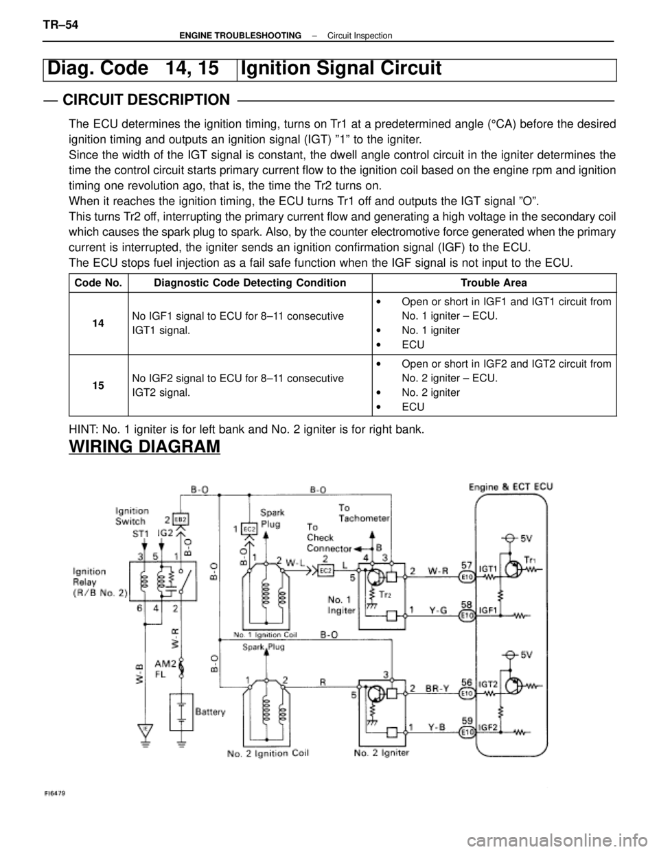
Diag. Code 14, 15Ignition Signal Circuit
CIRCUIT DESCRIPTION
The ECU determines the ignition timing, turns on Tr1 at a predetermined angle (5CA) before the desired
ignition timing and outputs an ignition signal (IGT) º1º to the \
igniter.
Since the width of the IGT signal is constant, the dwell angle control circuit in the ignit\
er determines the
time the control circuit starts primary current flow to the ignition coil bas\
ed on the engine rpm and ignition
timing one revolution ago, that is, the time the Tr2 turns on.
When it reaches the ignition timing, the ECU turns Tr1 off and outputs the IGT signal ºOº.
This turns Tr2 off, interrupting the primary current flow and generating a high voltage i\
n the secondary coil
which causes the spark plug to spark. Also, by the counter electromotive force\
generated when the primary
current is interrupted, the igniter sends an ignition confirmation signal (IGF\
) to the ECU.
The ECU stops fuel injection as a fail safe function when the IGF signal\
is not input to the ECU.
Code No.Diagnostic Code Detecting ConditionTrouble Area
14No IGF1 signal to ECU for 8±11 consecutive
IGT1 signal.
w Open or short in IGF1 and IGT1 circuit from
No. 1 igniter ± ECU.
w No. 1 igniter
w ECU
15No IGF2 signal to ECU for 8±11 consecutive
IGT2 signal.
wOpen or short in IGF2 and IGT2 circuit from
No. 2 igniter ± ECU.
w No. 2 igniter
w ECU
HINT: No. 1 igniter is for left bank and No. 2 igniter is for right bank.
WIRING DIAGRAM
TR±54±
ENGINE TROUBLESHOOTING Circuit Inspection
WhereEverybodyKnowsYourName
Page 3670 of 4087
DIAGNOSTIC CHART
Are there any other codes (Besides 21 or
28) being output?
Replace oxygen sensor.
Go to relevant diag. code chart.
HINT: If diag. code 21 is output, replace the front side main oxygen sensor.If diag. code 28 is output, replace the rear side main oxygen sensor.
WIRING DIAGRAM
TR±62±
ENGINE TROUBLESHOOTING Circuit Inspection
WhereEverybodyKnowsYourName