1991 LEXUS SC400 steering
[x] Cancel search: steeringPage 218 of 4087

3. Grease should not be applied to the steering wheel pad and the pad should not b\
e cleaned with detergents
of any kind.
4. Store the steering wheel pad where the ambient temperature remains below 93 °C (200 °F), without high
humidity and away from electrical noise.
5. When using electric welding, first disconnect the airbag connector (yellow \
color and 2 pins) under the steering column near the combination switch connector before starting work.
6. When disposing of a vehicle or the steering wheel pad alone, the airbag shou\
ld be deployed using an SST before disposal (See page AB±91). Perform the operation in a place away from electrical noise.
CENTER AIRBAG SENSOR ASSEMBLY
The connector of the center airbag sensor assembly should be connected or d\
isconnected with the sensor
mounted on the floor. It the connector is connected or disconnected while the center airbag \
sensor assem-
bly is not mounted to the floor, it could cause undesired ignition of the airbag system.
WIRE HARNESS AND CONNECTOR
The airbag system wire harness is integrated with the cowl wire harness ass\
embly. The wires for the airbag
wire harness are encased in a yellow corrugated tube. All the connectors\
for the system are also a standard
yellow color. If the airbag system wire harness becomes disconnected or the connecto\
r becomes broken
due to an accident, etc., repair or replace it as shown on page AB±20.
AB±4
SRS AIRBAG
± General Description
WhereEverybodyKnowsYourName
Page 219 of 4087

OPERATION
FUNCTION OF COMPONENTS
1. FRONT AIRBAG SENSORA front airbag sensor is mounted inside each of the front
fenders. The sensor unit is a mechanical type. When the sen-
sor detects deceleration force above a predetermined limit in
a collision, the contacts in the sensor make contact, sending
a signal to the center airbag sensor assembly. The sensor
cannot be disassembled.
2. SPIRAL CABLE (in COMBINATION SWITCH) A spiral cable is used as an electrical joint from the vehicle
body side to the steering wheel.
3. STEERING WHEEL PAD (with AIRBAG) The inflater and bag of the airbag system are stored in the
steering wheel pad and cannot be disassembled.
The inflater contains a squib, igniter charge, gas generant,
etc., and inflates the bag in case of a frontal collision.
4. AIRBAG WARNING LIGHT The airbag warning light is located on the combination meter.
It goes on to alert the driver of trouble in the system when a
malfunction is detected in the center airbag sensor assembly
self±diagnosis. In normal operating condition when the igni-
tion switch is turned to the ACC or ON position, the light goes
on for about 6 seconds and then goes off.
5. CENTER AIRBAG SENSOR ASSEMBLY The center airbag sensor assembly is mounted on the floor
inside the center cluster. The center airbag sensor assembly
consists of a center airbag sensor, safing sensors, ignition
control and drive circuit, diagnosis circuit, etc. It receives sig-
nals f rom the airbag sensors, judges whether the airbag must
be activated or not and diagnoses system malfunctions. AB±5
± OperationSRS AIRBAG
WhereEverybodyKnowsYourName
Page 222 of 4087

(4) Connector Twin±Lock MechanismWith this mechanism connectors (male and female connectors) are locked by \
two locking devices to
increase connection reliability. If the primary lock is incomplete, ribs interfere and prevent the seco\
nd-
ary lock.
When the vehicle is involved in a frontal collision in the hatched area (Fi\
g. 1) and the shock is larger than a prede-
termined level, the airbag is activated automatically. Safing sensors are designed to go on at a smaller decelera-
tion rate than the front and center airbag sensors. As illustrated in Fig. 2\
below, ignition is caused when current
flows to the squib, which happens when a safing sensor and a front airbag sen\
sor and/or the center airbag sen-
sor go on simultaneously.
When a deceleration force acts on the sensors, it causes the squib to ignite\
. Gas is then generated, increasing
the pressure inside the bag rapidly. The inflated bag breaks open the steering wheel pad. Bag inflation then
ends, and the gas is discharged through discharge holes provided behind the b\
ag. The bag becomes deflated
as a result.
AB±8SRS AIRBAG ± Operation
WhereEverybodyKnowsYourName
Page 223 of 4087

INSPECTION ITEMS AND REPLACEMENT REQUIREMENTS
If a Vehicle is brought in for an airbag system inspection, or if a vehicle wh\
ich has been involved in a collision
is inspected, perform the inspection in accordance with the following proc\
edure. If any problems are discovered,
replace the affected part with a new one.
Steering Wheel Pad (with Airbag), Steering Wheel and Spiral
Cable
INSPECTION ITEMS
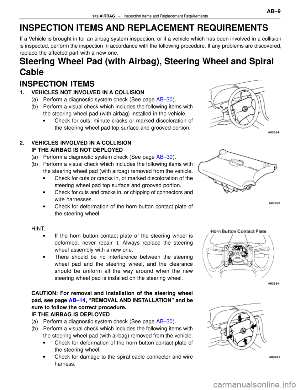
1. VEHICLES NOT INVOLVED IN A COLLISION(a) Perform a diagnostic system check (See page AB±30).
(b) Perform a visual check which includes the following items with the steering wheel pad (with airbag) installed in the vehicle.
w Check for cuts, minute cracks or marked discoloration of
the steering wheel pad top surface and grooved portion.
2. VEHICLES INVOLVED IN A COLLISION IF THE AIRBAG IS NOT DEPLOYED
(a) Perform a diagnostic system check (See page AB±30).
(b) Perform a visual check which includes the following items with the steering wheel pad (with airbag) removed from the vehicle.
w Check for cuts or cracks in, or marked discoloration of the
steering wheel pad top surface and grooved portion.
w Check for cuts and cracks in, or chipping of connectors and
wire harnesses.
w Check for deformation of the horn button contact plate of
the steering wheel.
HINT: w If the horn button contact plate of the steering wheel is
deformed, never repair it. Always replace the steering
wheel assembly with a new one.
w There should be no interference between the steering
wheel pad and the steering wheel, and the clearance
should be uniform all the way around when the new
steering wheel pad is installed on the steering wheel.
CAUTION: For removal and installation of the steering wheel
pad, see page AB±14, ªREMOVAL AND INSTALLATIONº and be
sure to follow the correct procedure.
IF THE AIRBAG IS DEPLOYED
(a) Perform a diagnostic system check (See page AB±30).
(b) Perform a visual check which includes the following items with the steering wheel pad (with airbag) removed from the vehicle.
w Check for deformation of the horn button contact plate of
the steering wheel.
w Check for damage to the spiral cable connector and wire
harness.
AB±9SRS AIRBAG ± Inspection Items and Replacement Requirements
WhereEverybodyKnowsYourName
Page 224 of 4087

HINT:
w If the horn button contact plate of the steering wheel is deformed, never \
repair it. Always replace the
steering wheel assembly with a new one.
w There should be no interference between the steering wheel pad and the steeri\
ng wheel, and the
clearance should be uniform all the way around when the new steering wheel pad is\
installed on the
steering wheel.
REPLACEMENT REQUIREMENTS
In the following cases, replace the steering wheel pad, steering wheel or \
spiral cable.
CAUTION: For replacement of the steering wheel pad, see page AB±16, ªREMOVAL AND INSTALLA-
TIONº and be sure to follow the correct procedure.
w If the airbag has been deployed.
w If the steering wheel pad or spiral cable has been found to be faulty in\
troubleshooting.
w If the steering wheel pad, steering wheel or spiral cable has been found t\
o be faulty during the check
in item 1±(b) or 2±(b).
w If the steering wheel pad has been dropped.
Front Airbag Sensor
INSPECTION ITEMS
1. VEHICLES NOT INVOLVED IN A COLLISION
w Perform a diagnostic system check (See page AB±30).
2. VEHICLES INVOLVED IN A COLLISION (a) Perform a diagnostic system check (See page AB±30).
(b) If the front fender of the car or its periphery is damaged, perform visual check for damage to the front airbag
sensor, which includes the following items even if the
airbag was not deployed:
w Bracket deformation.
w Peeling of paint from the bracket.
w Cracks, dents or chips in the case.
w Cracks and dents in, or chipping and scratches of
the connector.
w Peeling off of the label or damage to the series
number.
Also refer to the body dimension drawings on page
BO±133 and check the dimensions and mounting sur-
face angle of the body area where the front airbag sen-
sors are mounted.
AB±10SRS AIRBAG ± Inspection Items and Replacement Requirements
WhereEverybodyKnowsYourName
Page 227 of 4087

PREPARATION
SST (SPECIAL SERVICE TOOLS)
09082±00700SRS Airbag
Deployment Tool
09213±31021Crankshaft Pulley
Puller
09843±18020Diagnosis Check
Wiring
Steering wheel
RECOMMENDED TOOLS
09042±00010Torx Socket
T30
09042±00020Torx Socket
T30
09082±00015TOYOTA
Electrical Tester
Center airbag sensor assembly
Steering wheel pad
EQUIPMENT
Part NameNote
Torque wrench
AB±13SRS AIRBAG ± Preparation
WhereEverybodyKnowsYourName
Page 228 of 4087

REMOVAL AND INSTALLATION OF
COMPONENT PARTS
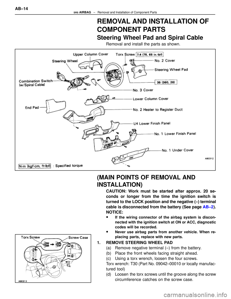
Steering Wheel Pad and Spiral Cable
Removal and install the parts as shown.
(MAIN POINTS OF REMOVAL AND
INSTALLATION)
CAUTION: Work must be started after approx. 20 se-
conds or longer from the time the ignition switch is
turned to the LOCK position and the negative (±) terminal
cable is disconnected from the battery (See page AB±2).
NOTICE:
wIf the wiring connector of the airbag system is discon-
nected with the ignition switch at ON or ACC, diagnostic
codes will be recorded.
wNever use airbag parts from another vehicle. When re-
placing parts, replace with new parts.
1. REMOVE STEERING WHEEL PAD (a) Remove negative terminal (±) from the battery.
(b) Place the front wheels facing straight ahead.
(c) Using a torx wrench, loosen the four screws.
Torx wrench: T30 (Part No. 09042±00010 or locally manufac-
tured tool)
(d) Loosen the torx screws until the groove along the screwcircumference catches on the screw case.
AB±14
SRS AIRBAG
± Removal and Installation of Component Parts
WhereEverybodyKnowsYourName
Page 229 of 4087

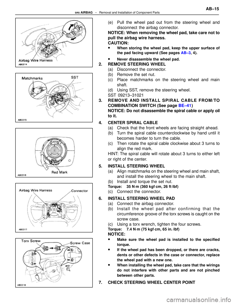
(e) Pull the wheel pad out from the steering wheel anddisconnect the airbag connector.
NOTICE: When removing the wheel pad, take care not to
pull the airbag wire harness.
CAUTION:
wWhen storing the wheel pad, keep the upper surface of
the pad facing upward (See pages AB±3, 4).
wNever disassemble the wheel pad.
2. REMOVE STEERING WHEEL
(a) Disconnect the connector.
(b) Remove the set nut.
(c) Place matchmarks on the steering wheel and mainshaft.
(d) Using SST, remove the steering wheel.
SST 09213±31021
3. REMOVE AND INSTALL SPIRAL CABLE FROM/TO COMBINATION SWITCH (See page BE±41)
NOTICE: Do not disassemble the spiral cable or apply oil
to it.
4. CENTER SPIRAL CABLE (a) Check that the front wheels are facing straight ahead.
(b) Turn the spiral cable counterclockwise by hand until it
becomes harder to turn the cable.
(c) Then rotate the spiral cable clockwise about 3 turns to align the red mark.
HINT: The spiral cable will rotate about 3 turns to either left
or right of the center.
5. INSTALL STEERING WHEEL (a) Align matchmarks on the steering wheel and main shaft,
and install the steering wheel to the main shaft.
(b) Install and torque the set nut.
Torque: 35 N Vm (360 kgf Vcm, 26 ft Vlbf)
(c) Connect the connector.
6. INSTALL STEERING WHEEL PAD (a) Connect the airbag connector.
(b) I n s t a l l t h e w heel pad after confirming that the
circumference groove of the torx screws is caught on the
screw case.
(c) Using a torx wrench, tighten the four screws.
Torque: 7.4 N Vm (75 kgf Vcm, 65 in. Vlbf)
NOTICE:
wMake sure the wheel pad is installed to the specified
torque.
wIf the wheel pad has been dropped, or there are cracks,
dents or other defects in the case or connector, replace
the wheel pad with a new one.
wWhen installing the wheel pad, take care that the wirings
do not interfere with other parts and are not pinched
between other parts.
7. CHECK STEERING WHEEL CENTER POINT AB±15
SRS AIRBAG
± Removal and Installation of Component Parts
WhereEverybodyKnowsYourName