Page 1241 of 4087
mm (in.)
BO6852
BO6852
(Two-Dimensional Distance) (Three-Dimensional Distance)
SymbolName Hole dia.
Symbol Name Hole dia.
A, a Strut bar installation hole inner
14 (0.55)F, fLower arm installation hole front 26
y14
(1.02 y0.55)
B, b Differential carrier installation nut 12 (0.47) nut G, gRear suspension member standard
hole
20 (0.78)
C, c Rear suspension member standard
hole 20 (0.78)
H, hLower arm installation hole rear 26
y14
(1.02 y0.55)
D, d Lower arm installation hole front 26
yl4
1.02 y0.55 I, i
Upper arm installation hole rear 14 (0.55)
E, e Upper arm installation hole front 14 (0.55)
Suspension Crossmember (Cont'd)
BODY DIMENSIONSDI-12
WhereEverybodyKnowsYourName
Page 1247 of 4087

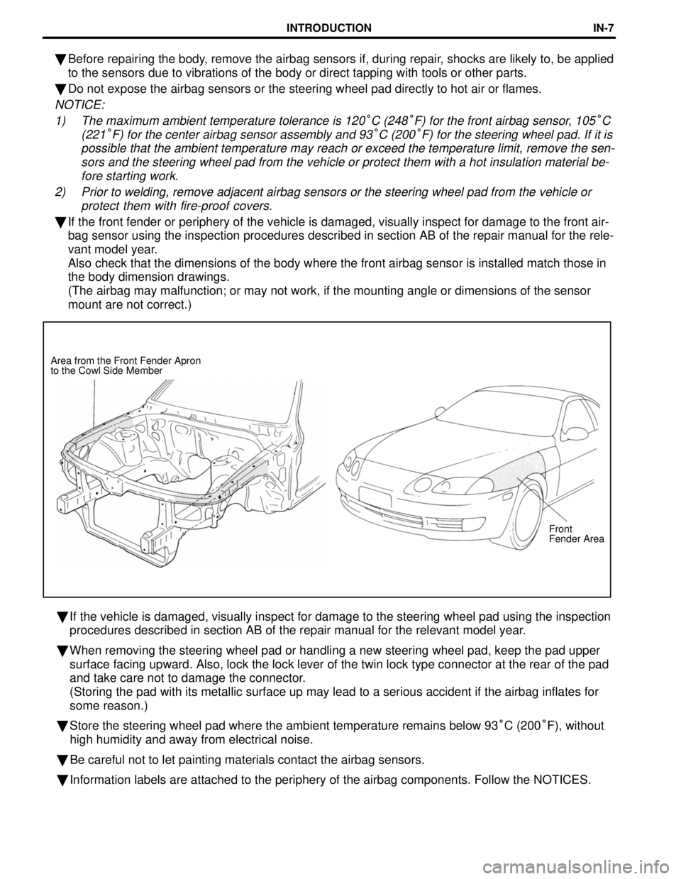
Front
Fender Area
Area from the Front Fender Apron
to the Cowl Side Member
�
Before repairing the body, remove the airbag sensors if, during repair, shocks are likely to, be applied
to the sensors due to vibrations of the body or direct tapping with tool\
s or other parts.
� Do not expose the airbag sensors or the steering wheel pad directly to h\
ot air or flames.
NOTICE:
1) The maximum ambient temperature tolerance is 120
°C (248°F) for the front airbag sensor, 105°C
(221
°F) for the center airbag sensor assembly and 93°C (200°F) for the steering wheel pad. If it is
possible that the ambient temperature may reach or exceed the temperatur\
e limit, remove the sen- sors and the steering wheel pad from the vehicle or protect them with a \
hot insulation material be-fore starting work.
2) Prior to welding, remove adjacent airbag sensors or the steering wheel p\
ad from the vehicle or protect them with fire-proof covers.
�If the front fender or periphery of the vehicle is damaged, visually ins\
pect for damage to the front air-
bag sensor using the inspection procedures described in section AB of th\
e repair manual for the rele-
vant model year.
Also check that the dimensions of the body where the front airbag sensor\
is installed match those in
the body dimension drawings.
(The airbag may malfunction; or may not work, if the mounting angle or \
dimensions of the sensor
mount are not correct.)
� If the vehicle is damaged, visually inspect for damage to the steering w\
heel pad using the inspection
procedures described in section AB of the repair manual for the relevant\
model year.
� When removing the steering wheel pad or handling a new steering wheel pa\
d, keep the pad upper
surface facing upward. Also, lock the lock lever of the twin lock type c\
onnector at the rear of the pad
and take care not to damage the connector.
(Storing the pad with its metallic surface up may lead to a serious acc\
ident if the airbag inflates for
some reason.)
� Store the steering wheel pad where the ambient temperature remains below\
93 °C (200 °F), without
high humidity and away from electrical noise.
� Be careful not to let painting materials contact the airbag sensors.
� Information labels are attached to the periphery of the airbag component\
s. Follow the NOTICES.
INTRODUCTIONIN-7
WhereEverybodyKnowsYourName
Page 1248 of 4087

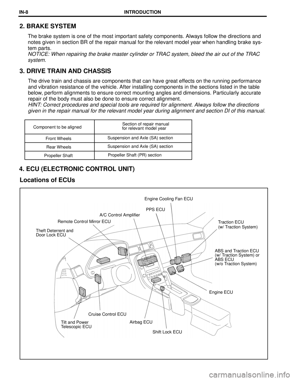
Shift Lock ECU
Tilt and Power
Telescopic ECU
Airbag ECU
Cruise Control ECU Engine ECUABS and Traction ECU
(w/ Traction System) or
ABS ECU
(w/o Traction System)
Theft Deterrent and
Door Lock ECU
(w/ Traction System)
Traction ECU
Remote Control Mirror ECU A/C Control Amplifier
PPS ECU
Engine Cooling Fan ECU
Component to be aligned
Section of repair manual
for relevant model year
Front Wheels Suspension and Axle (SA) section
Rear Wheels Suspension and Axle (SA) section
Propeller Shaft Propeller Shaft (PR) section
2. BRAKE SYSTEM
The brake system is one of the most important safety components. Always \
follow the directions and
notes given in section BR of the repair manual for the relevant model ye\
ar when handling brake sys-
tem parts.
NOTICE: When repairing the brake master cylinder or TRAC system, bleed t\
he air out of the TRAC
system.
3. DRIVE TRAIN AND CHASSIS
The drive train and chassis are components that can have great effects on the running performance
and vibration resistance of the vehicle. After installing components in \
the sections listed in the table
below, perform alignments to ensure correct mounting angles and dimensions. P\
articularly accurate
repair of the body must also be done to ensure correct alignment.
HINT: Correct procedures and special tools are required for alignment. Alway\
s follow the directionsgiven in the repair manual for the relevant model year during alignment \
and section DI of this manual.
4. ECU (ELECTRONIC CONTROL UNIT)
Locations of ECUs
INTRODUCTIONIN-8
WhereEverybodyKnowsYourName
Page 2992 of 4087
1. DISCONNECT INTERMEDIATE SHAFT
(a) Position the front wheels facing straight ahead.
(b) Using the seat belt of the driver's seat, fix the steering wheelso that it does not turn.
(c) Place matchmarks on the intermediate shaft and control valve shaft.
(d) Loosen the bolt on the upper side of the intermediate shaft,
remove the bolt on the lower side and disconnect the
intermediate shaft.
2. DISCONNECT TIE ROD ENDS
(a) Remove the cotter pin and nut.
(b) Using SST, disconnect the tie rod end from the knuckle arm. SST 09628±62011
3. CONNECT INTERMEDIATE SHAFT
(a) Set the gear housing so that it matches the dimensions shown below, with the gear housing at the center point.
±
STEERING POWER STEERINGSR±143
WhereEverybodyKnowsYourName
Page 2995 of 4087
(c) Place matchmarks on the intermediate shaft and controlvalve shaft.
(d) Loosen the bolt on the upper side of the intermediate shaft, remove the bolt on the lower side and disconnect the
intermediate shaft.
2. DISCONNECT TIE ROD ENDS
(a) Remove the cotter pin and nut.
(b) Using SST, disconnect the tie rod end from the knuckle arm. SST 09628±62011
3. CONNECT INTERMEDIATE SHAFT
(a) Set the gear housing so that it matches the dimensions shown below, with the gear housing at the center point.
(b) Align matchmarks on the intermediate shaft and control valve
shaft and connect them.
Torque: 35 N Vm (360 kgf Vcm, 26 ft Vlbf)
SR±146±
STEERING POWER STEERING
WhereEverybodyKnowsYourName
Page 3130 of 4087

6. COVER STEERING WHEEL PAD WITH CARDBOARDBOX OR TIRES
Covering Method Using Cardboard Box:
Cover the steering wheel pad with the cardboard box and
weigh the cardboard box down in four places with a at least
196 N (20 kgf, 44 lbf).
Size of cardboard box:
Must exceed the following dimensions±
x = 460 mm (18.11 in.) When dimension y of the cardboard box exceeds the
diameter of the disc wheel with tire the steering wheel
pad is tied to±
x = 460 mm (18.11 in.) + width of tire
y = 650 mm (25.59 in.)
NOTICE: If a cardboard box smaller than the size speci-
fied is used, the cardboard box will be broken by the
shock of the airbag deployment.
Covering Method Using Tires:
Place at least 3 tires without disc wheel on top of the disc
wheel with tire to which the steering wheel pad is tied.
Tire size: Must exceed the following dimensions± Width 185 mm (7.28 in.)
Inner diam 360 mm (14.17 in.)
CAUTION: Do not use tires with disc wheels.
NOTICE: The tires by marked by the airbag deployment,
so use redundant tires.
7. AIRBAG DEPLOYMENT
(a) Connect the SST red clip to the battery positive (+) terminal and the black clip to the battery negative (±) terminal.
(b) Confirm that no±one is within 10 m (33 ft) of the disc wheel the steering wheel pad is tied to.
(c) Press the SST activation switch and deploy the airbag. HINT: The airbag deploys simultaneously as the LED of the
SST activation switch lights up.
RS±26±
SUPPLEMENTAL RESTRAINT SYSTEM STEERING WHEEL PAD AND SPIRAL CABLE
WhereEverybodyKnowsYourName
Page 3142 of 4087

CAUTION: If a wire harness which is too thin or some oth-
er thing is used to tie down the front passenger airbag as-
sembly, it may be snapped by the shock when the airbag
is deployed, this is highly dangerous.
Always use a wire harness for vehicle use which is at
least 1.25 mm
2 (0.0019 in)2.
(1) Wrap the wire harness around the tire, passing the wire
harness at least 3 times through the installation hole on
the left and right sides of the front passenger airbag as-
sembly.
(2) Position the front passenger airbag assembly inside the tire with the airbag door facing inside.
Tie the wire harness to the tire.
Tire size: Must exceed the following dimensions
Width 185 mm (7.28 in.)
Inner diam 360 mm (14.17 in.)
CAUTION:
wMake sure the wire harness is tight. It is very dangerous
if a loose wire harness results in the front passenger
airbag assembly coming free due to the shock of the
airbag deploying.
w Always tie down the front passenger airbag assembly
with the airbag door facing inside.
NOTICE: The tire will be marked by the airbag deploy-
ment, so use a redundant tire.
3. CONFIRM FUNCTIONING OF SST (See page RS±27)
SST 09082±00700
RS±38
±
SUPPLEMENTAL RESTRAINT SYSTEM FRONT PASSENGER AIRBAG ASSEMBLY
WhereEverybodyKnowsYourName
Page 3145 of 4087

FRONT AIRBAG SENSOR
INSPECTION ITEMS
RS015±0C
1. VEHICLES NOT INVOLVED IN A COLLISIONPerform a diagnostic system check.
(See page RS±59)
2. VEHICLES INVOLVED IN A COLLISION
(a) Perform a diagnostic system check. (See page RS±59)
(b) If the front fender of the car or its periphery is damaged, perform visual check for damage to the front airbag sensor,
which includes the following items even if the airbag was not
deployed:
wBracket deformation.
w Peeling of paint from the bracket.
w Cracks, dents or chips in the case.
w Cracks and dents in, or chipping and scratches of the
connector.
w Peeling off of the label or damage to the series number.
Also refer to the body dimension drawings in the BODY sec-
tion and check the dimensions and mounting surface angle
of the body area where the front airbag sensors are mounted.
(The SRS may malfunction, or may not work, if the mounting
angle or dimensions of the sensor mount are not correct.)
REPLACEMENT REQUIREMENTS
RS016±06
In the following cases, replace the front airbag sensor.
NOTICE: for replacement of the front airbag sensor, see
page RS±42 , ªFRONT AIRBAG SENSOR REMOVAL AND
INSTALLATIONº and be sure to follow the correct proce-
dure.
w If the SRS has been deployed in a collision.
(Replace both the left and right airbag sensors.)
w If the front airbag sensor has been found to be faulty in
troubleshooting.
w If the front airbag sensor has been found to be faulty
during the check in item 2±(b).
w If the front airbag sensor has been dropped.
±
SUPPLEMENTAL RESTRAINT SYSTEM FRONT AIRBAG SENSORRS±41
WhereEverybodyKnowsYourName