Page 1233 of 4087
BO6847
mm (in.)
(Three-Dimensional Distance)
Hole dia.
18 (0.71)
18 (0.71)
10 (0.39) screw
12 (0.47) screw
Name
Front floor reinforcement standard hole
Rear floor side member standard hole
Suspension member bracket installation nut rear = outer
Transport hook installation nut front = outer
Symbol
L, l
M, m
P, p
Q, q
Hole dia.
6 (0.24) screw
18 (0.71) 13 (0.51)
18 (0.71)
Name
Radiator duct installation nut
Front side member standard holeFront suspension crossmember installation hole
Front side member standard hole
Symbol
A, a
D, d F, f
I, i
UNDER BODY
BODY DIMENSIONSDI-4
WhereEverybodyKnowsYourName
Page 1234 of 4087
BO6847
mm (in.)
(Three-Dimensional Distance)
Hole dia.
10 (0.39) screw
14 (0.55) screw
10 (0.39) screw
Name
Propeller shaft center support bearing installation nut
Rear suspension member installation nut
Suspension member bracket installation nut rear = outer
Symbol
K, k
N, n
P, p
Hole dia.
9 (0.35)
18 (0.71)
10 (0.39) screw
Name
Front crossmember working hole
Front suspension crossmember installation nut
Engine rear mounting member installation hole
Symbol
B, bH, h J, j
UNDER BODY (Cont'd)
BODY DIMENSIONSDI-5
WhereEverybodyKnowsYourName
Page 1235 of 4087
BO6847
mm (in.)
(Two-Dimensional Distance)
Hole dia.
18 (0.71) 18 (0.71)
10 (0.39) screw
12 (0.47) screw
Name
Front floor reinforcement standard hole
Rear floor side member standard hole
Suspension member bracket installation nut rear = outer
Transport hook installation nut front = outer
Symbol
L, l
M, m P, p
Q, q
Hole dia.
6 (0.24) screw
18 (0.71)
13 (0.51)
18 (0.71)
Name
Radiator duct installation nut
Front side member standard hole
Front suspension crossmember installation hole
Front side member standard hole
Symbol
A, aD, d F, f
I, i
UNDER BODY (Cont'd)
BODY DIMENSIONSDI-6
WhereEverybodyKnowsYourName
Page 1236 of 4087
BO6847
NOTICE: True up the mounting section ofthe front airbag sensor very carefully and
accurately so that the sensor can bemounted at the correct angle.
Imaginary
Standard
Line
mm (in.)
(Two-Dimensional Distance)
Hote dia.
10 (0.39) nut
10 (0.33) nut
18 (0.71)
14 (0.55) nut 9 (0.35)
Name
Engine rear mounting member installation nut-front Propeller shaft center support bearing installation nut
Front floor reinforcement standard hole
Rear suspension member installation nut Rear spring support hole-front
Symbol
J, j
K, k
L, l
N, n
O, o
Hole dia.
9 (0.35)
9 (0.35)
8 (0.31) nut
13 y11 (0.51 y0.43)14 (0.55) nut
Name
Front crossmember working hole
Airbag front sensor installation hole
Airbag front sensor installation nut Front spring support hole = outer
Front suspension crossmember installation nut
Symbol
B, b
C, c
E, e
G, g H, h
UNDER BODY (Cont'd)
BODY DIMENSIONSDI-7
WhereEverybodyKnowsYourName
Page 1237 of 4087

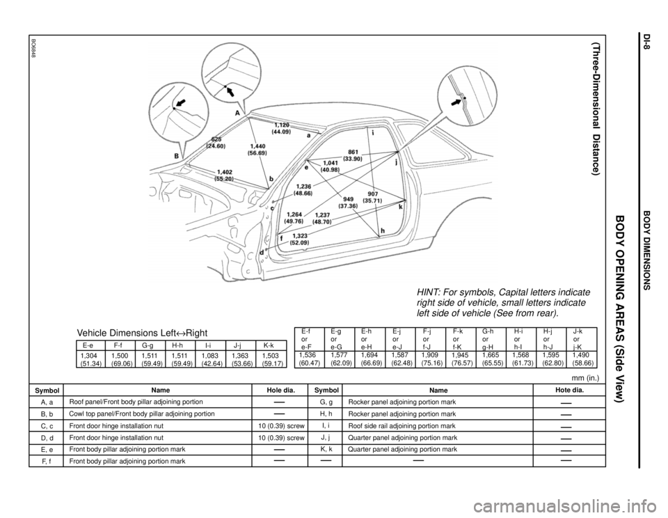
BO6848
E-e
1,304
(51.34) 1,500
(69.06)F-fVehicle Dimensions Left
eRight
G-g
1,511
(59.49) H-h
1,511
(59.49) I-i
1,083
(42.64) 1,363
(53.66)J-j
1,503
(59.17)K-k
E-f
or
e-F
1,536
(60.47) 1,577
(62.09)E-g
or
e-G
1,694
(66.69)E-h
or
e-H
1,587
(62.48)E-j
or
e-J
1,909
(75.16)F-j
or
f-J
HINT: For symbols, Capital letters indicate
right side of vehicle, small letters indicate
left side of vehicle (See from rear).
F-k
or
f-K
1,945
(76.57) G-h
or
g-H
1,665
(65.55) H-i
or
h-I
1,568
(61.73) 1,595
(62.80)H-j
or
h-J
1,490
(58.66)
mm (in.)J-k
or
j-K
(Three-Dimensional Distance)
Hote dia.
Name
Rocker panel adjoining portion mark
Rocker panel adjoining portion mark
Roof side rail adjoining portion mark
Quarter panel adjoining portion mark
Quarter panel adjoining portion mark
Symbol
G, g
H, h
I, i
J, j
K, k
Hole dia.
10 (0.39) screw
10 (0.39) screw
Name
Roof panel/Front body pillar adjoining portion
Cowl top panel/Front body pillar adjoining portion
Front door hinge installation nut
D, d Front door hinge installation nut
Front body pillar adjoining portion mark
Front body pillar adjoining portion mark
Symbol
A, a
B, b
C, c
E, e
F, f
BODY OPENING AREAS (Side View)
BODY DIMENSIONSDI-8
WhereEverybodyKnowsYourName
Page 1238 of 4087
BO6849
mm (in.)
(Three-Dimensional Distance)
Hole dia.18 (0.71)
Name
Opening trough/Lower back panel adjoining portion
Upper back panel center mark
Rear floor side member standard hole
Symbol
P, pQ
R, r
Hole dia.
Name
Roof panel/Quarter panel adjoining portion
Quarter panel/Upper back panel adjoining portion
Quarter panel/Upper beck panel adjoining portion
Opening trough/Quarter panel adjoining portion
Symbol
L, l
M, m
N, n
O, o
BODY OPENING AREAS (Rear View)
BODY DIMENSIONSDI-9
WhereEverybodyKnowsYourName
Page 1239 of 4087
mm (in.)
BO6850
BO6850
(Three-Dimensional Distance) (Three-Dimensional Distance)
SymbolName Hole dia. Symbol Name
Hole dia.
A, a Steering gear box installation hole
front 12 (0.47)
E, eLower arm installation hole-front
25
y16
(0.98 y0.63)
B, b Upper arm installation hole front 14 (0.55) F, f Lower arm installation hole rear25
y16
(0.98 y0.63)
C, c Suspension crossmember installation
hole front - lower
15 (0.59) G, g Upper arm installation hole rear
14 (0.55)
D, d Steering gear box installation hole-
lower 12 (0.47)
H, hSuspension crossmember installation
hole rear-lower
RH 15
y13 (0.59 y0.51)
LH 13 (0.51)
SUSPENSION CROSSMEMBER DIMENSION DRAWINGS
BODY DIMENSIONSDI-10
WhereEverybodyKnowsYourName
Page 1240 of 4087
mm (in.)
BO6851
BO6851
(Two-Dimensional Distance) (Three-Dimensional Distance)
SymbolName Hole dia. Symbol Name Hole die.
I, i Suspension crossmember installation
hole front-lower
18 (0.71) L, lSuspension crossmember installation
hole rear-lower 18 (0.71)
J, j Lower arm installation hole-front 30
y16
(1.18 y0.63) M, mSuspension crossmember installation
hole rear-lower
18 (0.71)
K, k Lower arm installation hole rear 30
y16
(1.18 y0.63)
Suspension Crossmember (Cont'd)
BODY DIMENSIONSDI-11
WhereEverybodyKnowsYourName