Page 949 of 4087
NOYES
NGOK
OKNG
INSPECTION PROCEDURE
1Is diagnostic trouble code output for the engine?
Perform diagnostic trouble code check on page EG±523 or EG±305 .
Repair circuit indicated by the code output.
2Check voltage between terminal VTH of TRAC ECU and body ground.
C
OK
P1. Remove TRAC ECU with connectors still con-
nected.
2. Remove intake air duct.
3. Turn ignition switch on.
Measure voltage between terminal VTH of TRAC ECU
and body ground, when the main throttle valve is turned
from fully closed position to fully opened position by
hand
In addition, as the main throttle valve is turned, the
voltage should increase gradually w ith out interrup-
tion.
Go to step �.
3Check for open and short in harness and connector between terminal VTH o\
f TRAC ECU and
terminal VTO1 of ECM (See page IN±33).
Repair or replace harness or connector.
±
BRAKE SYSTEM TRACTION CONTROL SYSTEM (TRAC)BR±203
WhereEverybodyKnowsYourName
Page 951 of 4087
OKNG
NGOK
6Check for open and short in harness and connector between terminal VTA1 of ECM and main
throttle position sensor (See page IN±33
).
Repair or replace harness or connector.
Adjust or replace main throttle position sensor
(See page EG±333 or EG±205 ).
7Check voltage between terminal IDL1 of TRAC ECU and body ground.
C
OK
PTurn ignition switch on.
Measure voltage between terminal IDL1 of TRAC ECU
and body ground, when the main throttle valve is fully
closed and fully opened.
Check and replace TRAC ECU.
±
BRAKE SYSTEM TRACTION CONTROL SYSTEM (TRAC)BR±205
WhereEverybodyKnowsYourName
Page 953 of 4087
OKNG
10Check main throttle position sensor (See page EG±609 or EG±389 ).
Adjust or replace main throttle position sensor (See
page EG±333 or EG±205).
Check and replace ECM.
±
BRAKE SYSTEM TRACTION CONTROL SYSTEM (TRAC)BR±207
WhereEverybodyKnowsYourName
Page 954 of 4087

DTC47, 48Sub±Throttle Position Sensor Circuit
CIRCUIT DESCRIPTION
This sensor detects the opening angle of the sub±throttle valve and sends the appropriate signals to the ECU.
If a trouble signal is input, the ECU prohibits TRAC control.
DTC No.DTC Detecting ConditionTrouble Area
47
When any of the following (1) through (3) is detected:
(1) Deviation of 5 steps or more to the closedside of the idle step during sub±throttleinitial check.
(2) Voltage at terminal IDL2 switch is OFF evenafter sub±throttle is driven to fully closedposition during
sub±throttle initial check 4.
(3) Voltage at terminal VSH is 1.45 V or morefor at least 0.15 sec. while idle switch is ON.
Sub±throttle position sensor
Open or short in IDL2 circuit
ECM
TRAC ECU
48
Either of the following (1) or (2) continues for atleast
0.12 sec.
(1) Input voltage of TRAC ECU terminal VSH:4.3 V or more.
(2) Input voltage of TRAC ECU terminal VSHis 0.2 V or less while IDL2 switch OFF.
Sub±throttle position sensor
Open or short in VSH circuit
ECM
TRAC ECU
BR±208±
BRAKE SYSTEM TRACTION CONTROL SYSTEM (TRAC)
WhereEverybodyKnowsYourName
Page 957 of 4087
NOYES
NGOK
OKNG
INSPECTION PROCEDURE
1Is diagnostic trouble code output for the engine?
Perform diagnostic trouble code check on page EG±523 or EG±305 .
Repair circuit indicated by the code output.
2Check voltage between terminal VSH or TRAC ECU and body ground.
C
OK
P1. Remove TRAC ECU with connectors still con-
nected.
2. Remove intake air duct.
3. Disconnect step motor connector.
4. Turn ignition switch on.
Measure voltage between terminal VSH or TRAC ECU
and body ground, when the sub±throttle valve is turned
from fully opened position to fully closed position.
In addition, as the sub±throttle valve is turned, the
voltage should increase gradually w ith out interrup-
tion.
Go to step
.
3Check for open and short in harness and connector between terminal VSH of TRAC ECU and
terminal VTO2 of ECM (See page IN±33).
Repair or replace harness or connector.
±
BRAKE SYSTEM TRACTION CONTROL SYSTEM (TRAC)BR±211
WhereEverybodyKnowsYourName
Page 959 of 4087
OKNG
NGOK
6Check for open and short in harness and connector between terminal VTA2 of ECM and sub±
throttle position sensor (See page IN±33
)
Repair or replace harness or connector.
Adjust or replace sub±throttle position sensor
(See page EG±333 or EG±205 ).
7Check voltage between terminal IDL2 of TRAC ECU and body ground.
C
OK
PTurn ignition switch on.
Measure voltage between terminal IDL2 or TRAC ECU
connector and body ground, when the sub±throttle
valve is fully closed and fully opened.
Check and replace TRAC ECU.
±
BRAKE SYSTEM TRACTION CONTROL SYSTEM (TRAC)BR±213
WhereEverybodyKnowsYourName
Page 961 of 4087
OKNG
10Check sub±throttle position sensor (See page EG±609 or EG±389 ).
Adjust or replace sub±throttle position sensor (See page
EG±333 or EG±205 ).
Check and replace ECM.
±
BRAKE SYSTEM TRACTION CONTROL SYSTEM (TRAC)BR±215
WhereEverybodyKnowsYourName
Page 1306 of 4087

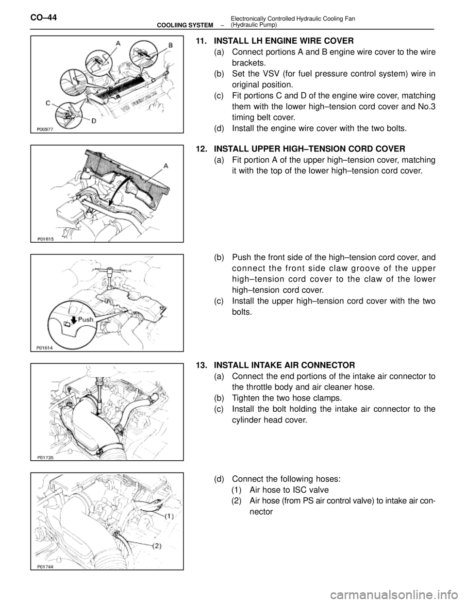
11. INSTALL LH ENGINE WIRE COVER(a) Connect portions A and B engine wire cover to the wirebrackets.
(b) Set the VSV (for fuel pressure control system) wire in
original position.
(c) Fit portions C and D of the engine wire cover, matching them with the lower high±tension cord cover and No.3
timing belt cover.
(d) Install the engine wire cover with the two bolts.
12. INSTALL UPPER HIGH±TENSION CORD COVER (a) Fit portion A of the upper high±tension cover, matchingit with the top of the lower high±tension cord cover.
(b) Push the front side of the high±tension cord cover, and connect the front side claw groove of the upper
high±tension cord cover to the claw of the lower
high±tension cord cover.
(c) Install the upper high±tension cord cover with the two bolts.
13. INSTALL INTAKE AIR CONNECTOR (a) Connect the end portions of the intake air connector tothe throttle body and air cleaner hose.
(b) Tighten the two hose clamps.
(c) Install the bolt holding the intake air connector to the cylinder head cover.
(d) Connect the following hoses: (1) Air hose to ISC valve
(2) Air hose (from PS air control valve) to intake air con- nector
CO±44
±
COOLIING SYSTEM Electronically Controlled Hydraulic Cooling Fan
(Hydraulic Pump)
WhereEverybodyKnowsYourName