Page 1308 of 4087
18. INSTALL BATTERY
19. FILL ENGINE WITH COOLANT (See page CO±7)
20. FILL COOLING FAN RESERVOIR TANK WITH FLUID (See pages CO±23 and 24)
21. START ENGINE AND CHECK FOR LEAKS
22. INSTALL ENGINE UNDER COVER
CO±46
±
COOLIING SYSTEM Electronically Controlled Hydraulic Cooling Fan
(Hydraulic Pump)
WhereEverybodyKnowsYourName
Page 1310 of 4087
REMOVAL OF HYDRAULIC MOTOR
(See Components on page CO±47)
1. REMOVE BATTERY CAUTION: Work must be started after approx. 20 se-
conds or longer from the time the ignition switch is
turned to the ºLOCKº position and the negative (±) termi-
nal cable is disconnected from the battery.
2. REMOVE ENGINE UNDER COVERS
3. DRAIN ENGINE COOLANT (See page CO±6)
4. REMOVE RADIATOR RESERVOIR TANK (a) Disconnect the coolant level sensor connector.
(b) Disconnect the following hoses:(1) Reservoir hose from water inlet housing
(2) Reservoir hose from radiator
(c) Remove the two bolts and reservoir tank bracket.
(d) Disconnect the reservoir tank from the reservoir tank bracket, and remove the reservoir tank.
5. DISCONNECT HOSES Disconnect the following hoses:(1) Upper radiator hose from radiator
(2) Pressure hose from hydraulic motor
(3) Return hose from hydraulic motor
CO±48
±
COOLIING SYSTEM Electronically Controlled Hydraulic Cooling Fan
(Hydraulic Motor)
WhereEverybodyKnowsYourName
Page 1319 of 4087
7. INSTALL RADIATOR RESERVOIR TANK(a) Install the reservoir tank to the reservoir tank bracket.
(b) Install the reservoir tank bracket with two bolts.
Torque: 4.9 N Vm (50 kgf Vcm, 43 in. Vlbf)
(c) Connect the following hoses:
(1) Reservoir hose to water inlet housing
(2) Reservoir hose to radiator
(d) Connect the coolant level sensor connector.
8. INSTALL BATTERY
9. FILL ENGINE WITH COOLANT (See page CO±7)
10. FILL COOLING FAN RESERVOIR TANK WITH FLUID
(See pages CO±23 and 24)
11. START ENGINE AND CHECK FOR LEAKS
12. INSTALL ENGINE UNDER COVER
±
COOLIING SYSTEM Electronically Controlled Hydraulic Cooling Fan
(Hydraulic Motor)CO±57
WhereEverybodyKnowsYourName
Page 1321 of 4087
4. REMOVE OIL COOLERRemove the three bolts and oil cooler.
INSPECTION OF OIL COOLER
INSPECT OIL COOLER
Check the oil cooler for damage or clogging.
If necessary, replace the oil cooler.
INSTALLATION OF OIL COOLER
(See Components on page CO±58)
1. INSTALL OIL COOLER Install the oil cooler with the three bolts.
Torque: 18 N Vm (180 kgf Vcm, 13 ft Vlbf)
2. CONNECT HOSES FROM OIL COOLER
Connect the following hoses:(1) Inlet hose (from reservoir tank)
(2) Outlet hose (from hydraulic motor)
3. INSTALL PS OIL COOLER Install the oil cooler with the two bolts.
4. REMOVE FENDER LINER
5. FILL COOLING FAN RESERVOIR TANK WITH FLUID
(See pages CO±23 and 24)
6. START ENGINE AND CHECK FOR LEAKS
±
COOLIING SYSTEM Electronically Controlled Hydraulic
Cooling Fan (Oil Cooler)CO±59
WhereEverybodyKnowsYourName
Page 1324 of 4087
(Water Temperature Sensor)
COMPONENTS FOR REMOVAL AND
INSTALLATION
INSPECTION OF WATER TEMPERATURE
SENSOR
1. DISCONNECT CABLE FROM NEGATIVE TERMINAL OFBATTERY
CAUTION: Work must be started after 20 seconds or
longer from the time the ignition switch is turned to the
ºLOCKº position and the negative (±) terminal cable is
disconnected from the battery.
2. REMOVE ENGINE UNDER COVER
3. DRAIN ENGINE COOLANT (See page CO±6)
4. REMOVE WATER TEMPERATURE SENSOR (a) Disconnect the water temperature sensor connector.
(b) Remove the water temperature sensor from left side ofthe radiator lower tank.
(c) Remove the O±ring from the water temperature sensor.
CO±62
±
COOLIING SYSTEM Electronically Controlled Hydraulic
Cooling Fan (Electronic Control Parts)
WhereEverybodyKnowsYourName
Page 1325 of 4087

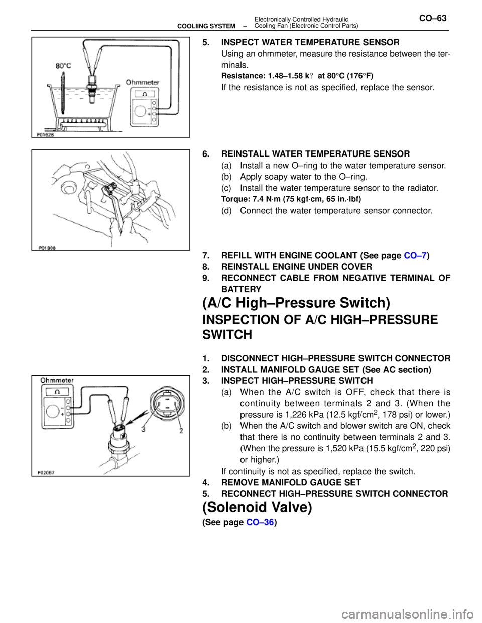
5. INSPECT WATER TEMPERATURE SENSORUsing an ohmmeter, measure the resistance between the ter-
minals.
Resistance: 1.48±1.58 k � at 80 5C (176 5F)
If the resistance is not as specified, replace the sensor.
6. REINSTALL WATER TEMPERATURE SENSOR (a) Install a new O±ring to the water temperature sensor.
(b) Apply soapy water to the O±ring.
(c) Install the water temperature sensor to the radiator.
Torque: 7.4 N Vm (75 kgf Vcm, 65 in. Vlbf)
(d) Connect the water temperature sensor connector.
7. REFILL WITH ENGINE COOLANT (See page CO±7)
8. REINSTALL ENGINE UNDER COVER
9. RECONNECT CABLE FROM NEGATIVE TERMINAL OF BATTERY
(A/C High±Pressure Switch)
INSPECTION OF A/C HIGH±PRESSURE
SWITCH
1. DISCONNECT HIGH±PRESSURE SWITCH CONNECTOR
2. INSTALL MANIFOLD GAUGE SET (See AC section)
3. INSPECT HIGH±PRESSURE SWITCH(a) Wh e n th e A/C switch is OFF, ch e ck th a t th e re iscontinuity between terminals 2 and 3. (When the
pressure is 1,226 kPa (12.5 kgf/cm
2, 178 psi) or lower.)
(b) When the A/C switch and blower switch are ON, check
that there is no continuity between terminals 2 and 3.
(When the pressure is 1,520 kPa (15.5 kgf/cm
2, 220 psi)
or higher.)
If continuity is not as specified, replace the switch.
4. REMOVE MANIFOLD GAUGE SET
5. RECONNECT HIGH±PRESSURE SWITCH CONNECTOR
(Solenoid Valve)
(See page CO±36)
±
COOLIING SYSTEM Electronically Controlled Hydraulic
Cooling Fan (Electronic Control Parts)CO±63
WhereEverybodyKnowsYourName
Page 1333 of 4087

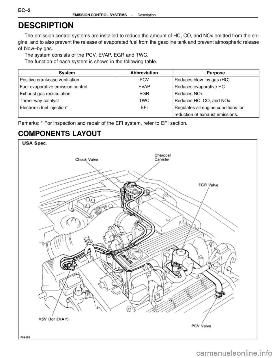
DESCRIPTION
The emission control systems are installed to reduce the amount of HC, CO, \
and NOx emitted from the en-
gine, and to also prevent the release of evaporated fuel from the gasoline ta\
nk and prevent atmospheric release
of blow±by gas. The system consists of the PCV, EVAP, EGR and TWC.
The function of each system is shown in the following table.
��������������� ���������������
System
��������� ���������
Abbreviation
�������������� ��������������
Purpose��������������� ���������������
Positive crankcase ventilation
��������� ���������
PCV
�������������� ��������������
Reduces blow±by gas (HC)��������������� ���������������
Fuel evaporative emission control
��������� ���������
EVAP
�������������� ��������������
Reduces evaporative HC��������������� ���������������
Exhaust gas recirculation
��������� ���������
EGR
�������������� ��������������
Reduces NOx��������������� ���������������
Three±way catalyst
��������� ���������
TWC
�������������� ��������������
Reduces HC, CO, and NOx��������������� ���������������
Electronic fuel injection*
��������� ���������
EFI
�������������� ��������������
Regulates all engine conditions for��������������� ������������������������ ����������������������� ��������������
reduction of exhaust emissions.
Remarks: * For inspection and repair of the EFI system, refer to EFI sec\
tion.
COMPONENTS LAYOUT
EC±2±
EMISSION CONTROL SYSTEMS Description
WhereEverybodyKnowsYourName
Page 1338 of 4087
SCHEMATIC DRAWING
PREPARATION
SST (SPECIAL SERVICE TOOLS)
IllustrationPart No.Part NameNote
09843±18020Diagnosis Check Wire
for EGR system inspection
RECOMMENDED TOOLS
IllustrationPart No.Part NameNote
09082±00015TOYOTA Electrical
Tester
EQUIPMENT
Part NameNote
Vacuum gaugeEGR system
Engine tune±up testerEngine speed
SSM (SPECIAL SERVICE MATERIALS)
Part NamePart No.Note
08833±00070THREE
BOND 1324BVSV
±
EMISSION CONTROL SYSTEMS Description, PreparationEC±3
WhereEverybodyKnowsYourName