Page 529 of 4087
(f) Remove twelve nuts, the front door trim ornament andthe door inside handle.
(g) Remove eight screws and armrest.
(h) Remove the door courtesy light.
4. REMOVE DOOR SPEAKER GRILLE Using a screwdriver, pry loose two clips and remove the cov-
er.
HINT: Tape the screwdriver tip before use.
5. REMOVE DOOR TRIM UPPER PANEL Remove six screws and pry out the panel.
6. REMOVE FRONT DOOR WEATHERSTRIP While pulling the weatherstrip by hand, remove the nine clips
using a clip remover.
HINT: Do not pull strongly on the weatherstrip as it may
tear.
7. REMOVE OUTSIDE REAR VIEW MIRROR AND SPEAKER
(a) Remove two bolts and the speaker, disconnect the connector.
(b) Remove two bolts and the mirror, disconnect the connector.
BO±34
±
BODY Front Door
WhereEverybodyKnowsYourName
Page 535 of 4087
14. INSTALL OUTSIDE REAR VIEW MIRROR(a) Install the mirror with two bolts, connect the connector.
(b) I n s t a l l t h e s peaker with two bolts, connect the
connector.
15. INSTALL FRONT DOOR WEATHERSTRIP Push down on the nine clips of the weatherstrip.
16. INSTALL DOOR TRIM UPPER PANEL (a) Push the panel into the frame.
(b) Tap in the three clips.
(c) Install the panel with six screws.
17. INSTALL DOOR SPEAKER GRILLE Slide the grille and tap the grille to install it.
18. INSTALL DOOR TRIM (a) Install the front door trim ornament and the door insidehandle with eleven nuts.
(b) Install the armrest with eight screws.
(c) Install the door curtesy switch.
(d) Install the two cables as shown.
(e) Connect the connector to the door curtesy switch.
BO±40
±
BODY Front Door
WhereEverybodyKnowsYourName
Page 560 of 4087

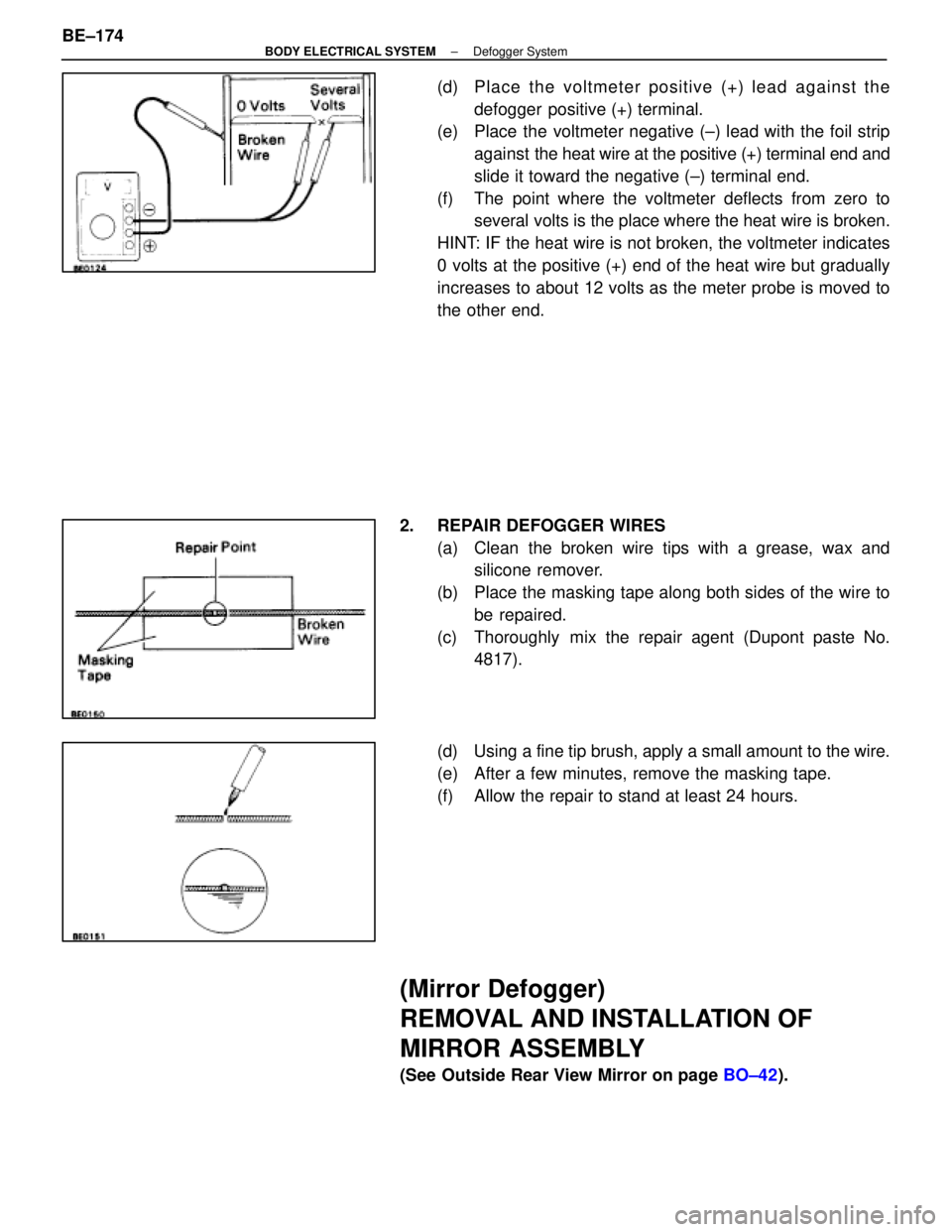
(d) Place the voltmeter positive (+) lead against thedefogger positive (+) terminal.
(e) Place the voltmeter negative (±) lead with the foil strip
against the heat wire at the positive (+) terminal end and
slide it toward the negative (±) terminal end.
(f) The point where the voltmeter deflects from zero to several volts is the place where the heat wire is broken.
HINT: IF the heat wire is not broken, the voltmeter indicates
0 volts at the positive (+) end of the heat wire but gradually
increases to about 12 volts as the meter probe is moved to
the other end.
2. REPAIR DEFOGGER WIRES (a) Clean the broken wire tips with a grease, wax andsilicone remover.
(b) Place the masking tape along both sides of the wire to be repaired.
(c) Thoroughly mix the repair agent (Dupont paste No. 4817).
(d) Using a fine tip brush, apply a small amount to the wire.
(e) After a few minutes, remove the masking tape.
(f) Allow the repair to stand at least 24 hours.
(Mirror Defogger)
REMOVAL AND INSTALLATION OF
MIRROR ASSEMBLY
(See Outside Rear View Mirror on page BO±42).
BE±174
±
BODY ELECTRICAL SYSTEM Defogger System
WhereEverybodyKnowsYourName
Page 569 of 4087

POWER MIRROR CONTROL
SYSTEM
Description
The Power Miror Control System carries out mirror left/right and up/down ad\
justments electrically when the Mir-
ror Switch is operated. In addition, operation of the Driving Position M\
emory and Return Switches makes it pos-
sible to store the adjusted position in memory and reproduce each adjustment \
when desired. The component
parts of this system and their functions are described in the following table\
.
Parts NameFunction
Outside Rear View
Mirror ECUThe Outside Rear View Mirror ECU is supplied with power from the DOME and RADIO
NO.2 fuses and is connected to the Tilt and Telescopic ECU, Mirror Switch, each
mirror motor and ground.
Rear View Adjustment
SwitchOperation of this switch sends left/right, up/down signals to Outside Re\
ar View Mirror
ECU.
Driving Position Memory
and Return SwitchesMemory and return signals are sent to the ECU via the Tilt and Telescopic ECU.
Mirror MotorThese motors operate on current from the Outside Rear View Mirror ECU, moving
the various parts of the mirror directly.
These sensors send signals about the motor positions to the ECU for stor\
ing in memory
and during return operation.
Left/Right Select SwitchThis switch is used to select operation of the Rear View Adjustment Switch for the
leftor right hand side mirror.
±
BODY ELECTRICAL SYSTEM Power Mirror Control SystemBE±183
WhereEverybodyKnowsYourName
Page 572 of 4087

Parts Inspection
(Mirror Switch)
REMOVAL AND INSTALLATION OF
MIRROR SWITCH
(See Instrument Panel on page BO±33)
INSPECTION OF MIRROR SWITCH
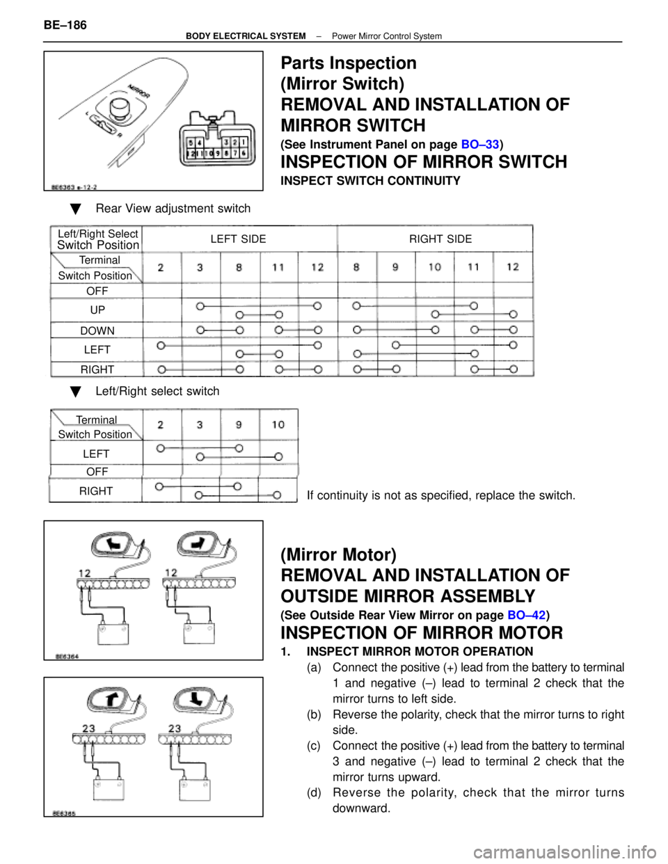
INSPECT SWITCH CONTINUITY
� Rear View adjustment switch
Left/Right Select
Switch Position
Terminal
Switch Position OFF
UP
DOWN LEFT
RIGHT LEFT SIDE RIGHT SIDE
�
Left/Right select switch
If continuity is not as specified, replace the switch.
(Mirror Motor)
REMOVAL AND INSTALLATION OF
OUTSIDE MIRROR ASSEMBLY
(See Outside Rear View Mirror on page BO±42)
INSPECTION OF MIRROR MOTOR
1. INSPECT MIRROR MOTOR OPERATION
(a) Connect the positive (+) lead from the battery to terminal
1 and negative (±) lead to terminal 2 check that the
mirror turns to left side.
(b) Reverse the polarity, check that the mirror turns to right side.
(c) Connect the positive (+) lead from the battery to terminal
3 and negative (±) lead to terminal 2 check that the
mirror turns upward.
(d) Re ve rse th e po la rity, ch e ck th a t th e mirro r tu rn s
downward.
BE±186
±
BODY ELECTRICAL SYSTEM Power Mirror Control System
Terminal
Switch Position
OFF
LEFT
RIGHT
WhereEverybodyKnowsYourName
Page 850 of 4087

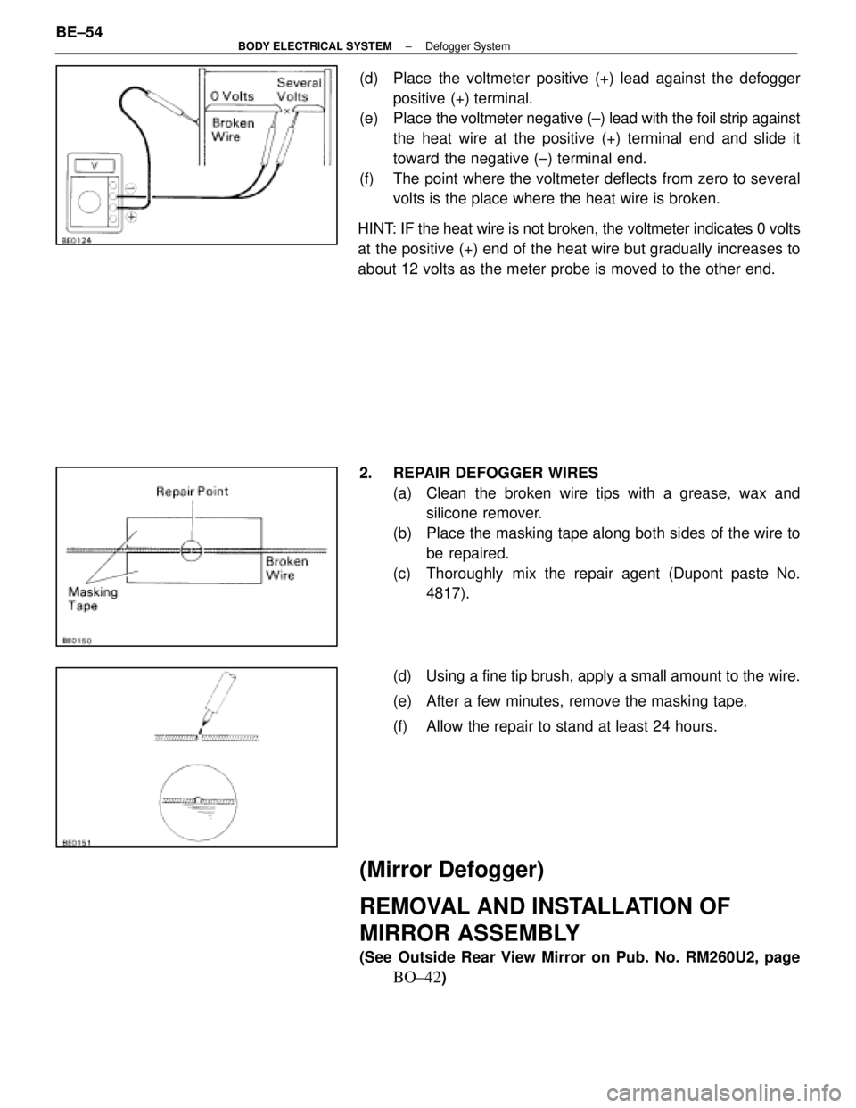
(d) Place the voltmeter positive (+) lead against the defoggerpositive (+) terminal.
(e) Place the voltmeter negative (±) lead with the foil strip against
the heat wire at the positive (+) terminal end and slide it
toward the negative (±) terminal end.
(f) The point where the voltmeter deflects from zero to several volts is the place where the heat wire is broken.
HINT: IF the heat wire is not broken, the voltmeter indicates 0 volts
at the positive (+) end of the heat wire but gradually increases to
about 12 volts as the meter probe is moved to the other end.
2. REPAIR DEFOGGER WIRES (a) Clean the broken wire tips with a grease, wax andsilicone remover.
(b) Place the masking tape along both sides of the wire to be repaired.
(c) Thoroughly mix the repair agent (Dupont paste No. 4817).
(d) Using a fine tip brush, apply a small amount to the wire.
(e) After a few minutes, remove the masking tape.
(f) Allow the repair to stand at least 24 hours.
(Mirror Defogger)
REMOVAL AND INSTALLATION OF
MIRROR ASSEMBLY
(See Outside Rear View Mirror on Pub. No. RM260U2, page
BO±42)
BE±54
±
BODY ELECTRICAL SYSTEM Defogger System
WhereEverybodyKnowsYourName
Page 1156 of 4087
LOCATION OF PLASTIC BODY PARTS
Outside Rear View Mirror (ABS)
Instrument Panel Safety Pad (PVC/PUR) Rear Spoiler (SMC)
Front Turn Signal Light (PC/PP)
Center Stop Light (PC)
Mead Light (PC/PP)
Head Light (PC/PP)
Front Bumper Extension
Mounting Bracket (PP)
Quarter Panel
Mud Guard (TPO)
Outside Moulding
Front Fender Mud Guard (TPO)
Front Spoiler (PUR) Cowl Top Ventilation Louver (PP)
Front Bumper Cover (PUR) Side Turn Signal Light (PMMA/ABS)
Cornering Light (PC)
HINT:
wResin material differs with model.
/ Made up of 2 or more kinds of materials.
PLASTIC BODY PARTSPP-4
WhereEverybodyKnowsYourName
Page 1246 of 4087

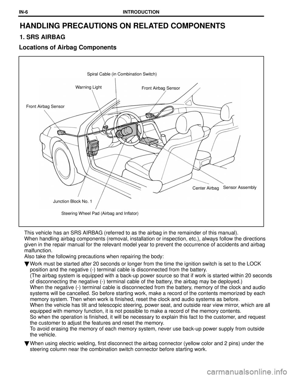
Steering Wheel Pad (Airbag and Inflator)
Junction Block No. 1 Center Airbag
Front Airbag Sensor
Front Airbag Sensor
Warning Light Spiral Cable (in Combination Switch)
HANDLING PRECAUTIONS ON RELATED COMPONENTS
1. SRS AIRBAG
Locations of Airbag Components
This vehicle has an SRS AIRBAG (referred to as the airbag in the remain\
der of this manual).
When handling airbag components (removal, installation or inspection, e\
tc.), always follow the directions
given in the repair manual for the relevant model year to prevent the oc\
currence of accidents and airbag
malfunction.
Also take the following precautions when repairing the body:
� Work must be started after 20 seconds or longer from the time the ignitio\
n switch is set to the LOCK
position and the negative (-) terminal cable is disconnected from the \
battery.
(The airbag system is equipped with a back-up power source so that if w\
ork is started within 20 seconds
of disconnecting the negative (-) terminal cable of the battery, the airbag may be deployed.)
When the negative (-) terminal cable is disconnected from the battery, memory of the clock and audio
systems will be cancelled. So before starting work, make a record of the\
contents memorized by each
memory system. Then when work is finished, reset the clock and audio sys\
tems as before.
When the vehicle has tilt and telescopic steering, power seat, and outsi\
de rear view mirror, which are all
equipped with memory function, it is not possible to make a record of th\
e memory contents.
So when the operation is finished, it will be necessary to explain this \
fact to the customer, and request
the customer to adjust the features and reset the memory.
To avoid erasing the memory of each memory system, never use back-up powe\
r supply from outside
the vehicle.
� When using electric welding, first disconnect the airbag connector (yel\
low color and 2 pins) under the
steering column near the combination switch connector before starting wo\
rk.
Sensor Assembly
INTRODUCTIONIN-6
WhereEverybodyKnowsYourName