1991 LEXUS SC400 gas type
[x] Cancel search: gas typePage 2021 of 4087

FUEL SYSTEM
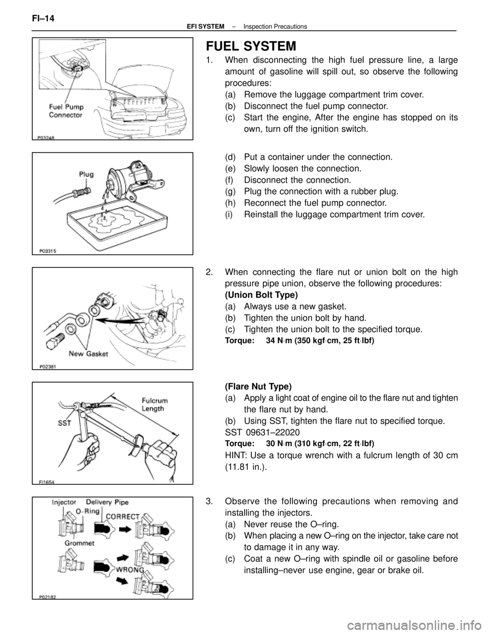
1. When disconnecting the high fuel pressure line, a largeamount of gasoline will spill out, so observe the following
procedures:
(a) Remove the luggage compartment trim cover.
(b) Disconnect the fuel pump connector.
(c) Start the engine, After the engine has stopped on itsown, turn off the ignition switch.
(d) Put a container under the connection.
(e) Slowly loosen the connection.
(f) Disconnect the connection.
(g) Plug the connection with a rubber plug.
(h) Reconnect the fuel pump connector.
(i) Reinstall the luggage compartment trim cover.
2. When connecting the flare nut or union bolt on the high pressure pipe union, observe the following procedures:
(Union Bolt Type)
(a) Always use a new gasket.
(b) Tighten the union bolt by hand.
(c) Tighten the union bolt to the specified torque.
Torque: 34 N Vm (350 kgf Vcm, 25 ft Vlbf)
(Flare Nut Type)
(a) Apply a light coat of engine oil to the flare nut and tighten
the flare nut by hand.
(b) Using SST, tighten the flare nut to specified torque.
SST 09631±22020
Torque: 30 N Vm (310 kgf Vcm, 22 ft Vlbf)
HINT: Use a torque wrench with a fulcrum length of 30 cm
(11.81 in.).
3. Observe the following precautions when removing and installing the injectors.
(a) Never reuse the O±ring.
(b) When placing a new O±ring on the injector, take care not
to damage it in any way.
(c) Coat a new O±ring with spindle oil or gasoline before installing±never use engine, gear or brake oil.
FI±14
±
EFI SYSTEM Inspection Precautions
WhereEverybodyKnowsYourName
Page 2026 of 4087

FUEL SYSTEM
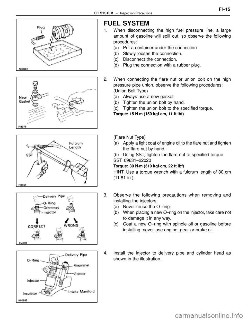
1. When disconnecting the high fuel pressure line, a largeamount of gasoline will spill out, so observe the following
procedures:
(a) Put a container under the connection.
(b) Slowly loosen the connection.
(c) Disconnect the connection.
(d) Plug the connection with a rubber plug.
2. When connecting the flare nut or union bolt on the high pressure pipe union, observe the following procedures:
(Union Bolt Type)
(a) Always use a new gasket.
(b) Tighten the union bolt by hand.
(c) Tighten the union bolt to the specified torque.
Torque: 15 N Vm (150 kgf Vcm, 11 ft Vlbf)
(Flare Nut Type)
(a) Apply a light coat of engine oil to the flare nut and tighten
the flare nut by hand.
(b) Using SST, tighten the flare nut to specified torque.
SST 09631±22020
Torque: 30 N Vm (310 kgf Vcm, 22 ft Vlbf)
HINT: Use a torque wrench with a fulcrum length of 30 cm
(11.81 in.).
3. Observe the following precautions when removing and installing the injectors.
(a) Never reuse the O±ring.
(b) When placing a new O±ring on the injector, take care not
to damage it in any way.
(c) Coat a new O±ring with spindle oil or gasoline before installing±never use engine, gear or brake oil.
4. Install the injector to delivery pipe and cylinder head as shown in the illustration. FI±15
EFI SYSTEM
± Inspection Precautions
WhereEverybodyKnowsYourName
Page 2522 of 4087

TORQUE SPECIFICATIONS
Part tightenedNVmkgf Vcmft Vlbf
Fuel line Union bolt type
Flare nut type2930022
Fuel pipe X Delivery pipe39400 29
Fuel pump bracket X Fuel tank5.455 48 in.Vlbf
Fuel pump set plate X Fuel tank3.940 35 in. Vlbf
Fuel tank X Body25250 18
Fuel sender gauge X Fuel tank2.930 26 in. Vlbf
Fuel inlet pipe X Fuel tank2.930 26 in. Vlbf
Fuel tank main tube X Fuel tank29300 22
Fuel tank return tube X Fuel tank29300 22
Fuel tank evaporation vent tube X Fuel tank29300 22
Air flow meter X Air cleaner case10100 7
Cold start injector X Air intake chamber7.880 69 in. Vlbf
Cold start injector tube X Cold start injector15150 11
Air intake chamber X Intake manifold18185 13
EGR pipe X Air intake chamber18185 13
EGR pipe X RH cylinder head18185 13
Cold start injector tube X RH Delivery pipe15150 11
Throttle body X Air intake chamber18185 13
Fuel return pipe X Fuel pressure regulator35360 26
Fuel pressure regulator X RH delivery pipe29300 22
Delivery pipe X Intake manifold18185 13
Fuel inlet hose X LH delivery pipe39400 29
for SST33340 24
ISC valve X Air intake chamber18185 13
Cold start injector time switch X Front water by±pass joint34350 25
Water temperature sensor X Front water by±pass joint20200 14
Water inlet housing X Water pump18185 13
EGR gas temperature sensor X EGR valve adaptor20200 14
EGR valve adaptor X Air intake chamber18185 13
EGR valve X EGR valve adaptor18185 13
Knock sensor X Cylinder block44450 33
Intake manifold X Cylinder head18185 13
Main oxygen sensor X Exhaust manifold44450 33
Sub±oxygen sensor X Exhaust manifold4445033
FI±142EFI SYSTEM ± Service Specifications
WhereEverybodyKnowsYourName
Page 2793 of 4087

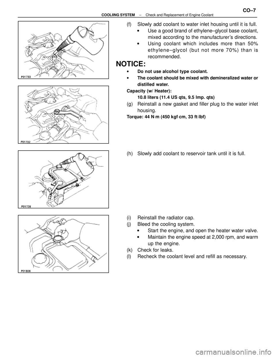
(f) Slowly add coolant to water inlet housing until it is full.w Use a good brand of ethylene±glycol base coolant,
mixed according to the manufacturer's directions.
w Using coolant which includes more than 50%
ethylene±glycol (but not more 70%) than is
recommended.
NOTICE:
w Do not use alcohol type coolant.
w The coolant should be mixed with demineralized water or
distilled water.
Capacity (w/ Heater): 10.8 liters (11.4 US qts, 9.5 lmp. qts)
(g) Reinstall a new gasket and filler plug to the water inlethousing.
Torque: 44 N Vm (450 kgf Vcm, 33 ft Vlbf)
(h) Slowly add coolant to reservoir tank until it is full.
(i) Reinstall the radiator cap.
(j) Bleed the cooling system.
w Start the engine, and open the heater water valve.
w Maintain the engine speed at 2,000 rpm, and warm
up the engine.
(k) Check for leaks.
(l) Recheck the coolant level and refill as necessary.
±
COOLIING SYSTEM Check and Replacement of Engine CoolantCO±7
WhereEverybodyKnowsYourName
Page 2886 of 4087

The 1 UZ±FE engine has 8±cylinders in a V±arrangement at a bank an\
gle of 905. From the front of the RH
bank cylinders are numbered 2±4±6±8, and from the front of the LH b\
ank cylinders are numbered 1 ±3±5±7.
The crankshaft is supported by 5 bearings specified by the inside of the cr\
ankcase. These bearings are made
of a copper and lead alloy. The crankshaft is integrated with 8 weights which are cast along with it\
for balancing. Oil holes are built
into the center of the crankshaft for supplying oil to the connecting ro\
ds, pistons and other components. The ignition order is 1±8±4±3±6±5±7±2. The cylinder\
head is made of aluminum alloy, with a cross flow
type intake and exhaust layout and with pent±roof type combustion chambers. The spark plugs are loca\
ted in
the center of the combustion chambers.
At the front and rear of the intake manifold, a water passage has been p\
rovided which connects the RH
and LH cylinder heads. Exhaust and intake valves are equipped with irregular pitch springs made\
of special valve spring carbon
steel which are capable of following no matter what the engine speed.
The RH and LH intake camshafts are driven by a single timing belt, and a ge\
ar on the intake camshaft en-
gages with a gear on the exhaust camshaft to drive it. The camshaft jour\
nal is supported at 5 (intake) or 4 (ex-
haust) places between the valve lifters of each cylinder and on the front end of the cylinder \
head. Lubrication
of the cam journal gear is accomplished by oil being supplied through the \
oiler port in the center of the camshaft. Adjustment of the valve clearance is done by means of an outer shim type\
system, in which valve adjusting
shims are located above the valve lifters. This permits replacement of the sh\
ims without removal of the cam-
shafts. Pistons are made of high temperature±resistant aluminum alloy, and a depression is built into the piston
head to prevent interference with valves.
Piston pins are the full±floating type, with the pins fastened to neither the piston boss nor the connecting
rods. Instead, snap rings are fitted on both ends of the pins, preventing the\
pins from falling out. The No.1 compression ring is made of steel and the No.2 compression ring\
is made of cast iron. The oil
ring is m ade of a combination of steel and stainless steel. The outer diameter of\
each piston ring is slightly larger
than the diameter of the piston and the flexibility of the rings allows them\
to hug the cylinder walls when they
are mounted on the piston. Compression rings No.1 and No.2 work to prevent \
the leakage of gas from the cylin-
der and the oil ring works to scrape oil off the cylinder walls to prevent it from entering the combustion chamber. The cylinder block is made of aluminum alloy with a bank angle of 90 5. Cast iron cylinders are installed
inside the cylinder block. It has 8 cylinders which are approximately twice the length of th\
e piston stroke. The
top of each cylinder is closed off by the cylinder heads and the lower end of the cylinders becomes the crank-
case, in which the crankshaft is installed. In addition, the cylinder bl\
ock contains a water jacket, through which
coolant is pumped to cool the cylinders. The No.1 and No.2 oil pans are bolted onto the bottom of the cylinder block\
. The No.1 oil pan is made of
aluminum alloy. The No.2 oil pan is an oil reservoir made of pressed steel sheet. An o\
il level sensor is installed
in the No.1 oil pan (If the oil level drops below a set level, a warnin\
g light lights up.). A oil pan baffle plate keeps
sufficient oil in the bottom of the No.2 oil pan even when the vehicle is tilted. \
This dividing plate also prevents
the oil from making waves when the vehicle is stopped suddenly and the oil \
shifts away from the oil pump suction
pipe. Plastic region tightening bolts are used for the cylinder head, main bearing ca\
p and connecting rod.
EM±4
±
ENGINE MECHANICAL Operation
WhereEverybodyKnowsYourName
Page 3113 of 4087

OPERATION
FUNCTION OF COMPONENTS
RS02M±04
1. STEERING WHEEL PAD (with AIRBAG)The inflater and bag of the supplemental restraint system are
stored in the steering wheel pad and cannot be disas-
sembled. The inflater contains a squib, igniter charge, gas
generant, etc., and inflates the bag in case of frontal collision.
2. SPIRAL CABLE (in COMBINATION SWITCH) A spiral cable is used as an electrical joint from the vehicle
body side to the steering wheel.
3. FRONT PASSENGER AIRBAG ASSEMBLY The inflater and bag of the supplemental restraint system are
stored in the front passenger airbag assembly and cannot be
disassembled.
The inflater contains a squib, igniter charge, gas generant,
etc., and inflates the bag in case of a frontal collision.
4. SRS WARNING LIGHT The SRS warning light is located on the combination meter.
It goes on to alert the driver of trouble in the system when a
malfunction is detected in the center airbag sensor assembly.
In normal operating conditions when the ignition switch is
turned to the ACC or ON position, the light goes on for about
6 seconds and then goes off.
5. FRONT AIRBAG SENSOR A front airbag sensor is mounted inside each of the front fend-
ers. The sensor unit is a mechanical type. When the sensor
detects deceleration force above a predetermined limit, con-
tacts is m ade in the sensor, sending a signal to the center air-
bag sensor assembly. The sensor cannot be disassembled.
±
SUPPLEMENTAL RESTRAINT SYSTEM OPERATIONRS±9
WhereEverybodyKnowsYourName
Page 3336 of 4087

(e) The drive shaft is designed to move + 20 mm from the normalposition.
Drive shaft standard length:
RH 598.5 mm (23.563 in.)
LH 553.5 mm (21.791 in.)
8. INSTALL NEW END COVER
(a) Pack grease into the end cover.
Grease capacity:50±55 g (0.11±0.12 lb, 1.8±1.9 oz.)
(b) Remove grease from the surface of the inboard joint facingthe cover.
(c) Glue on a new gasket, with the side with adhesive on it facing
toward the outer race side of the inboard joint.
(d) Align the bolt holes of the cover with those of the inboard joint.
(e) Install the 6 hexagon bolts and washer from the end cover side.
(f) Install the 6 nuts to the boot side.
(g) Using a 10 mm hexagon wrench, tighten the bolts. Do this in
the order shown, and repeat several times.
(h) Check that the claw of the end cover touches the inboard joint.
9. CHECK DRIVE SHAFT Check that operation of the joint is smooth within the sliding
region in the axial direction.
HINT: If a large angle is used for the cross±groove type joint,
the joint will feel like it is catching, but this does not indicate
an abnormality.
±
SUSPENSION AND AXLE REAR DRIVE SHAFTSA±73
WhereEverybodyKnowsYourName
Page 3810 of 4087

SERVICE HINTS FOR REFRIGERANT LEAK DETECTIONPage 1 of 3
Use of electronic leak detectors for checking A/C systems refrigerant leaka\
ge is the only
method approved by TMS. This type of leak detector is sensitive not onl\
y to refrigerant, but
also sensitive to numerous petrochemical substances (motor oil, gasolin\
e, solvents, etc.)
commonly found in a repair shop environment. Because this sensitivity c\
ould diminish the leak
detector 's capacity for accurate leak detection, some service hints have been pro\
vided to help
increase the accuracy of your diagnosis.
SERVICE HINTS:
1. Visual Inspection: Do a quick visual inspection under the hood for signs of refrigerant
leakage. Check for areas of heavy oil leakage at block and piping joint\
s. Many times
these areas have accumulated road dust and dirt.
2. Inspection with leak detector: NOTE: Make sure the system is fully charged. Operate
the system to increase refrigerant pressure. Shut the system off before inspecting with
leak detector.
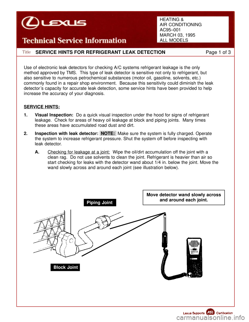
A. Checking for leakage at a joint:
Wipe the oil/dirt accumulation off the joint with a
clean rag. Do not use solvents to clean the joint. Refrigerant is heavi\
er than air so
start checking for leaks with the detector wand about 1/4 in. below the \
joint. Move the
wand slowly across and around each joint (see illustration below).
Piping Joint Move detector wand slowly across
and around each joint.
Block Joint
HEATING &
AIR CONDITIONING
AC95±001
MARCH 03, 1995
ALL MODELS
WhereEverybodyKnowsYourName