Page 828 of 4087
4. Headlight HI±Beam Lights Up
SwitchPosition
Ignition SwitchOFF or ON
Light Control SwitchHEAD
Headlight Dimmer SwitchHI
Condition: Battery Voltage " (3)
Continuity (20) " (21) " Ground
(18) " (17) " Ground
(16) " (17) " Ground
5. Headlight Flash
SwitchPosition
Ignition SwitchOFF or ON
Light Control SwitchOFF or TAIL or HEAD
Headlight Dimmer SwitchFLASH
Condition: Battery Voltage " (3)
Continuity (19) " (21) " Ground
(20) " (21) " Ground
BE±32±
BODY ELECTRICAL SYSTEM Lighting System
WhereEverybodyKnowsYourName
Page 833 of 4087
Parts Replacement ± Headlight
(Headlight)
REPLACEMENT OF HEADLIGHT
1. REMOVE HEADLIGHT(a) Remove battery (LH) or disconnect negative termial (±)from the battery (RH).
CAUTION: Work must be started after approx. 20 se-
conds or longer from the time the ignition switch is
turned to the ºLOCKº position and negative (±) terminal
cable is disconnected from the battery.
(b) Remove fender liner. ( BO±92)
(c) Remove a screw and two nuts.
(d) Disconnect connector.
(e) Remove headlight (Low Beam).
(f) Disconnect connector.
(g) Remove front bumper. ( BO±12)
(h) Remove the bolt.
(i) Remove headlight (High±Beam).
2. INSTALL HEADLIGHT For installation, follow the removed procedure in reverse.
±
BODY ELECTRICAL SYSTEM Lighting SystemBE±37
WhereEverybodyKnowsYourName
Page 835 of 4087
Parts Inspection ± Headlight System
(Combination Switch Assembly)
REMOVAL OF COMBINATION SWITCH
ASSEMBLY
1. REMOVAL FOLLOWING PARTS:(See page BO±112)
w No. 1 under cover
w No. 1 lower finish Panel
NOTICE:
w Turn the steering wheel and front wheels to the straight
ahead position.
w Turn the ignition switch to the OFF position, then remove
the battery negative terminal.
2. REMOVE STEERING WHEEL CENTER PAD
(a) Remove two covers.
(b) Using torx driver or wrench, remove the four torx screws.
Torx wrench T30 (09042±00010)
Torx driver T30 (09041±00030)
(c) Remove center pad and disconnect connector.
3. REMOVE STEERING WHEEL (a) Remove the steering nut.
(b) Using SST, remove steering wheel.
SST 09213±31021
4. REMOVE STEERING COLUMN COVER Remove three screws and steering column covers.
±
BODY ELECTRICAL SYSTEM Lighting SystemBE±39
WhereEverybodyKnowsYourName
Page 843 of 4087

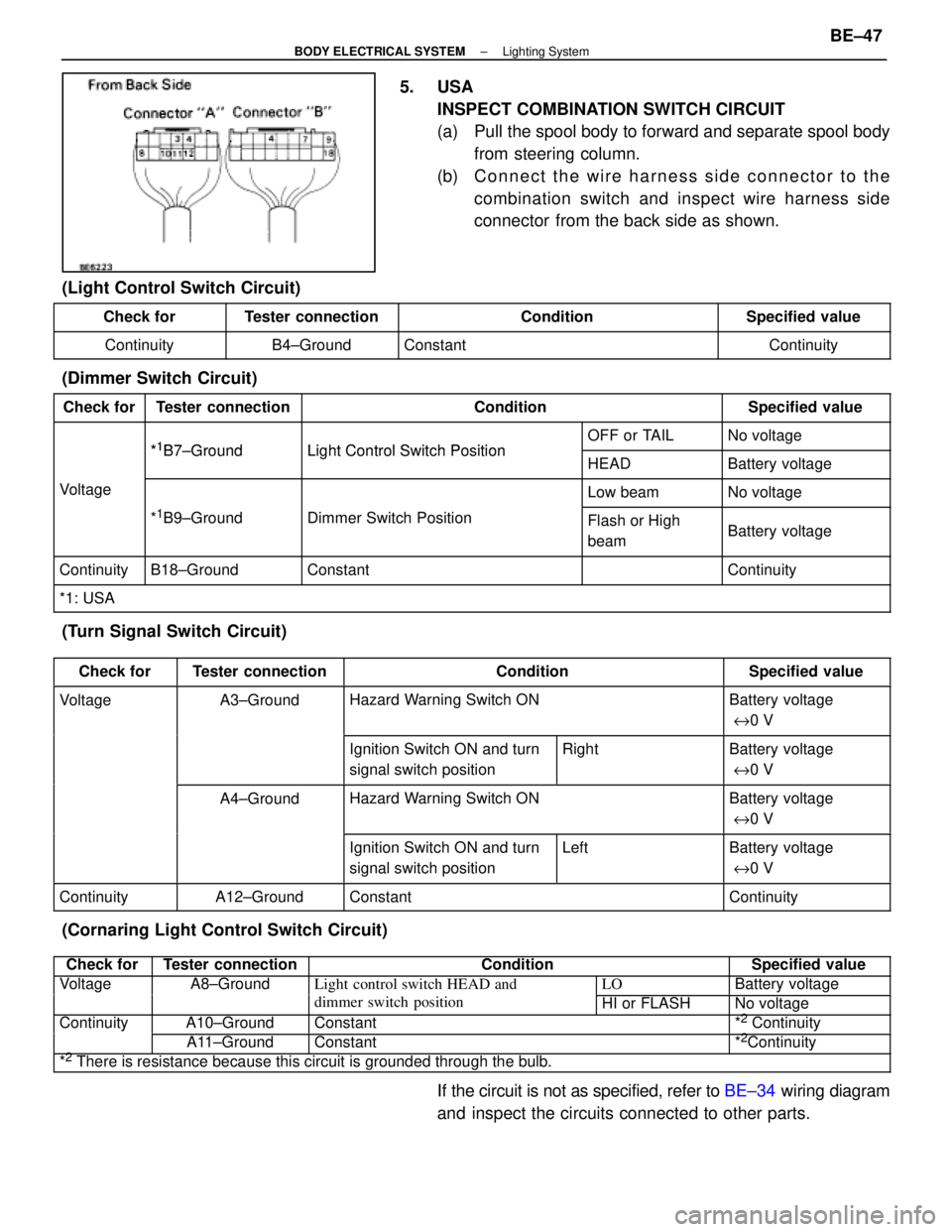
5. USAINSPECT COMBINATION SWITCH CIRCUIT
(a) Pull the spool body to forward and separate spool bodyfrom steering column.
(b) C onnect the wire harness side connector to the
combination switch and inspect wire harness side
connector from the back side as shown.
(Light Control Switch Circuit)
Check forTester connectionConditionSpecified value
ContinuityB4±GroundConstantContinuity
(Dimmer Switch Circuit)
Check forTester connectionConditionSpecified value
*1B7 GroundLight Control Switch PositionOFF or TAILNo voltage*1B7±GroundLight Control Switch PositionHEADBattery voltage
VoltageLow beamNo voltage
*1B9±GroundDimmer Switch PositionFlash or High
beamBattery voltage
ContinuityB18±GroundConstantContinuity
*1: USA
(Turn Signal Switch Circuit)
Check forTester connectionConditionSpecified value
VoltageA3±GroundHazard Warning Switch ONBattery voltage
e 0 V
Ignition Switch ON and turn
signal switch positionRightBattery voltage
e 0 V
A4±GroundHazard Warning Switch ONBattery voltage
e 0 V
Ignition Switch ON and turn
signal switch positionLeftBattery voltage
e 0 V
ContinuityA12±GroundConstantContinuity
(Cornaring Light Control Switch Circuit)
Check forTester connectionConditionSpecified value
VoltageA8±GroundLight control switch HEAD andLOBattery voltagegg
dimmer switch positionHI or FLASHNo voltage
ContinuityA10±GroundConstant*2 Continuityy
A11±GroundConstant*2Continuity
*2 There is resistance because this circuit is grounded through the bulb.
If the circuit is not as specified, refer to BE±34 wiring diagram
and inspect the circuits connected to other parts.
±
BODY ELECTRICAL SYSTEM Lighting SystemBE±47
WhereEverybodyKnowsYourName
Page 845 of 4087

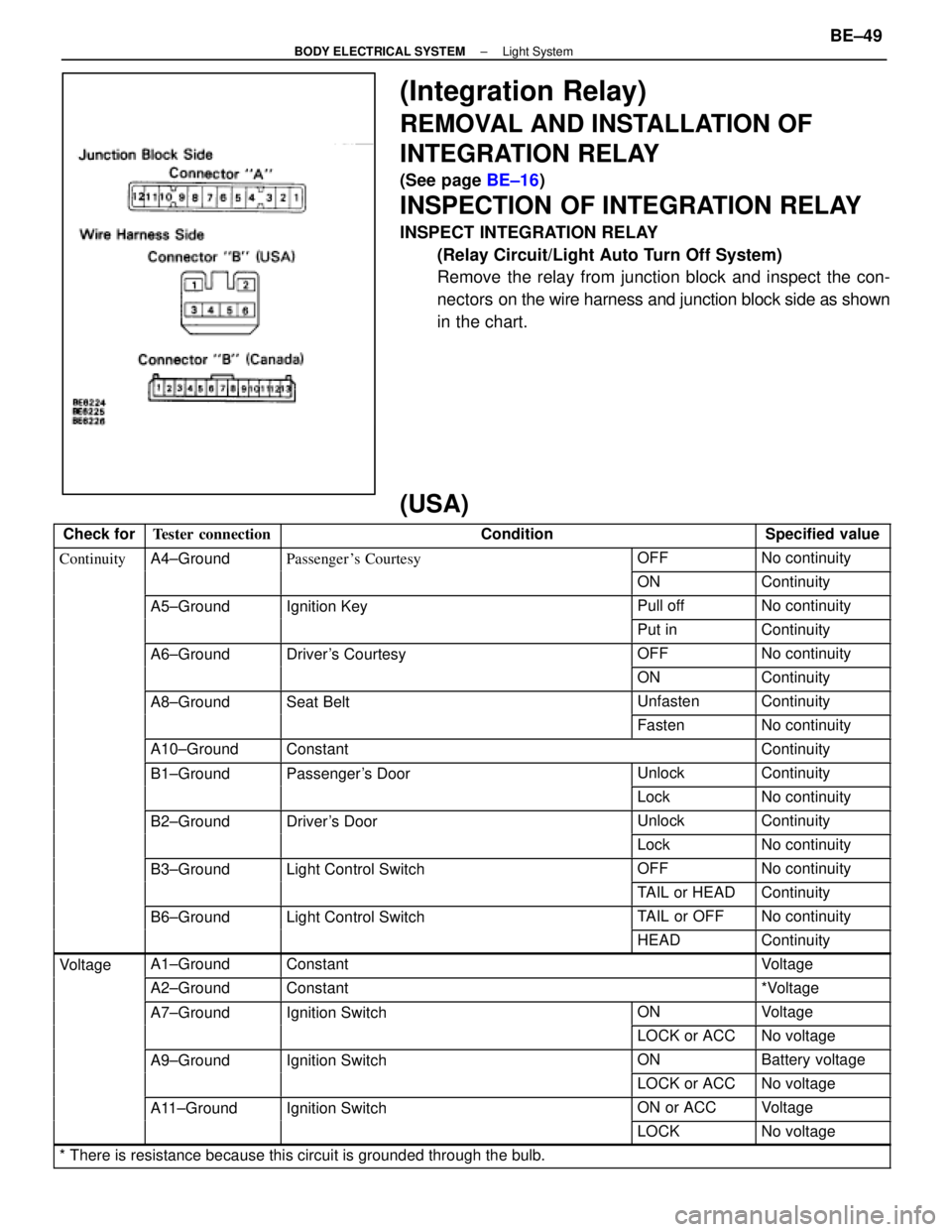
(Integration Relay)
REMOVAL AND INSTALLATION OF
INTEGRATION RELAY
(See page BE±16)
INSPECTION OF INTEGRATION RELAY
INSPECT INTEGRATION RELAY
(Relay Circuit/Light Auto Turn Off System)
Remove the relay from junction block and inspect the con-
nectors on the wire harness and junction block side as shown
in the chart.
(USA)
Check forTester connectionConditionSpecified value
ContinuityA4±GroundPassenger 's CourtesyOFFNo continuityygy
ONContinuity
A5±GroundIgnition KeyPull offNo continuitygy
Put inContinuity
A6±GroundDriver's CourtesyOFFNo continuityy
ONContinuity
A8±GroundSeat BeltUnfastenContinuity
FastenNo continuity
A10±GroundConstantContinuity
B1±GroundPassenger's DoorUnlockContinuityg
LockNo continuity
B2±GroundDriver's DoorUnlockContinuity
LockNo continuity
B3±GroundLight Control SwitchOFFNo continuityg
TAIL or HEADContinuity
B6±GroundLight Control SwitchTAIL or OFFNo continuityg
HEADContinuity
VoltageA1±GroundConstantVoltageg
A2±GroundConstant*Voltage
A7±GroundIgnition SwitchONVoltageg
LOCK or ACCNo voltage
A9±GroundIgnition SwitchONBattery voltageg
LOCK or ACCNo voltage
A11±GroundIgnition SwitchON or ACCVoltageg
LOCKNo voltage
* There is resistance because this circuit is grounded through the bulb.\
±
BODY ELECTRICAL SYSTEM Light SystemBE±49
WhereEverybodyKnowsYourName
Page 846 of 4087

(Canada)
Check forTester connectionConditionSpecified value
ContinuityA4±GroundPassenger's CourtesyOFFNo continuityygy
ONContinuity
A5±GroundIgnition KeyPull offNo continuitygy
Put inContinuity
A6±GroundDriver's CourtesyOFFNo continuityy
ONContinuity
A8±GroundSeat BeltUnfastenContinuity
FastenNo continuity
A10±GroundConstantContinuity
A12±GroundConstantContinuity
B1±GroundPassenger's DoorUnlockContinuityg
LockNo continuity
B2±GroundParking Brake
Switch PositionOFF (Switch pin
pushed in)No continuity
ON (Switch pin re-
leased)Continuity
B3±GroundDriver's DoorUnlockContinuity
LockNo continuity
B7±GroundHeadlight Dimmer
Switch PositionLow Beam or High
BeamNo continuity
FlashContinuity
B8±GroundHeadlight DimmerLow BeamNo continuityg
Switch PositionHigh Beam or FlashContinuity
B10±GroundLight Control SwitchOFFNo continuityg
HEAD or TAILContinuity
B12±GroundConstantContinuity
B13±GroundLight Control SwitchOFF or TAILNo continuityg
HEADContinuity
VoltageA1±GroundConstantVoltageg
A2±GroundConstant*Voltage
A7±GroundIgnition SwitchONVoltageg
LOCK or ACCNo voltage
A9±GroundIgnition SwitchON*Voltageg
LOCK or ACCNo voltage
A11±GroundIgnition SwitchON or ACCVoltageg
LOCKNo voltage
B4±GroundEngineSTOPNo voltageg
RunningVoltage
B11±GroundConstantVoltage
* There is resistance because this circuit is grounded through the bulb.\
If the circuit is as specified, trying replacing the relay with a
new one.
If the circuit is not as specified, refer to BE±35 wiring diagram
and inspect the circuit connected to other parts.
BE±50
±
BODY ELECTRICAL SYSTEM Light System
WhereEverybodyKnowsYourName
Page 847 of 4087

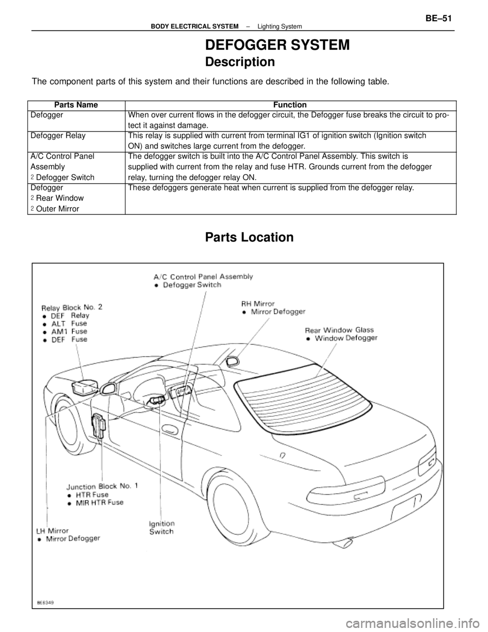
DEFOGGER SYSTEM
Description
The component parts of this system and their functions are described in the\
following table.
��������� ���������Parts Name������������������\
���������� ������������������\
����������Function
��������� ���������Defogger������������������\
���������� ������������������\
����������When over current flows in the defogger circuit, the Defogger fuse break\
s the circuit to pro-
tect it against damage.
��������� �
��������
���������
Defogger Relay������������������\
���������� �
������������������\
���������
������������������\
����������
This relay is supplied with current from terminal IG1 of ignition switch\
(Ignition switch
ON) and switches large current from the defogger.
��������� �
��������
���������
A/C Control Panel
Assembly
�
Defogger Switch������������������\
���������� �
������������������\
���������
������������������\
����������
The defogger switch is built into the A/C Control Panel Assembly. This switch is
supplied with current from the relay and fuse HTR. Grounds current from \
the defogger
relay, turning the defogger relay ON.
��������� �
��������
�
��������
���������
Defogger
�
Rear Window
� Outer Mirror������������������\
���������� �
������������������\
���������
�
������������������\
���������
������������������\
����������
These defoggers generate heat when current is supplied from the defogger\
relay.
Parts Location
±
BODY ELECTRICAL SYSTEM Lighting SystemBE±51
WhereEverybodyKnowsYourName
Page 849 of 4087

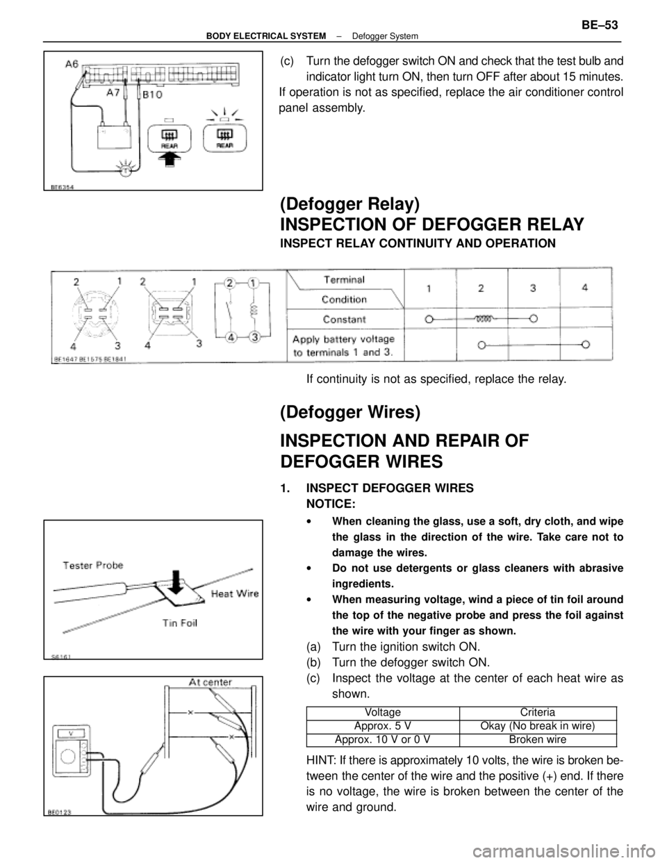
(c) Turn the defogger switch ON and check that the test bulb andindicator light turn ON, then turn OFF after about 15 minutes.
If operation is not as specified, replace the air conditioner control
panel assembly.
(Defogger Relay)
INSPECTION OF DEFOGGER RELAY
INSPECT RELAY CONTINUITY AND OPERATION
If continuity is not as specified, replace the relay.
(Defogger Wires)
INSPECTION AND REPAIR OF
DEFOGGER WIRES
1. INSPECT DEFOGGER WIRESNOTICE:
w When cleaning the glass, use a soft, dry cloth, and wipe
the glass in the direction of the wire. Take care not to
damage the wires.
w Do not use detergents or glass cleaners with abrasive
ingredients.
w When measuring voltage, wind a piece of tin foil around
the top of the negative probe and press the foil against
the wire with your finger as shown.
(a) Turn the ignition switch ON.
(b) Turn the defogger switch ON.
(c) Inspect the voltage at the center of each heat wire as
shown.
���������� ����������Voltage���������� ����������Criteria
����������Approx. 5 V����������Okay (No break in wire)���������� ����������Approx. 10 V or 0 V���������� ����������Broken wire
HINT: If there is approximately 10 volts, the wire is broken be-
tween the center of the wire and the positive (+) end. If there
is no voltage, the wire is broken between the center of the
wire and ground.
±
BODY ELECTRICAL SYSTEM Defogger SystemBE±53
WhereEverybodyKnowsYourName