Page 813 of 4087
REPLACEMENT OF RELAY BLOCK NO. 2
(B) IN RELAY BLOCK NO. 2
1. REMOVE RELAY BLOCK NO. 2 (B)
(a) Disconnect the battery terminals.CAUTION: Work must be started after approx. 20 se-
conds or longer from the time the ignition switch is
turned to the ºLOCKº position and negative (±) terminal
cable is disconnected from the battery.
(b) Remove the relay block No. 2 cover.
(c) Remove the relay block No. 2 lower cover.
2. INSTALL RELAY BLOCK NO. 2 (B) For installation follow the removal procedure in reverse.
±
BODY ELECTRICAL SYSTEM Power SourceBE±17
WhereEverybodyKnowsYourName
Page 816 of 4087

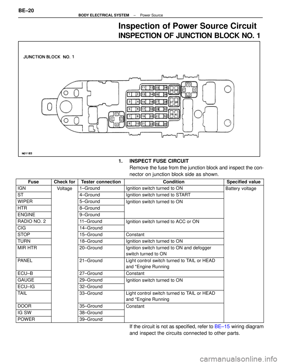
Inspection of Power Source Circuit
INSPECTION OF JUNCTION BLOCK NO. 1
1. INSPECT FUSE CIRCUITRemove the fuse from the junction block and inspect the con-
nector on junction block side as shown.
FuseCheck forTester connectionConditionSpecified value
IGNVoltage1±GroundIgnition switch turned to ONBattery voltage
ST
g
4±GroundIgnition switch turned to START
yg
WIPER5±GroundIgnition switch turned to ON
HTR8±Ground
g
ENGINE9±Ground
RADIO NO. 211±GroundIgnition switch turned to ACC or ON
CIG14±Ground
g
STOP15±GroundConstant
TURN18±GroundIgnition switch turned to ON
MIR HTR20±GroundIgnition switch turned to ON and defogger
switch turned to ON
PANEL21±GroundLight control switch turned to TAIL or HEAD
and *Engine Running
ECU±B27±GroundConstant
GAUGE29±GroundIgnition switch turned to ON
ECU±IG32±Ground
g
TAIL33±GroundLight control switch turned to TAIL or HEAD
and *Engine Running
DOOR35±GroundConstant
IG SW38±Ground
POWER39±Ground
If the circuit is not as specified, refer to BE±15 wiring diagram
and inspect the circuits connected to other parts.
BE±20
±
BODY ELECTRICAL SYSTEM Power Source
WhereEverybodyKnowsYourName
Page 819 of 4087
INSPECTION OF RELAY BLOCK NO. 4
AND NO. 5 RELAY BLOCK
1. INSPECT FUSE CIRCUITRemove the fuse from the relay block and inspect the con-
nector on relay block side as shown.
FuseCheck forTester connectionConditionSpecified value
STHTRVoltage2±GroundIgnition Switch Turn to ONBattery voltage
If the circuit is not as specified, refer to BE±15 wiring diagram
and inspect the circuits connected to other parts.
2. INSPECT RELAY CIRCUIT
Remove the relay from the relay block and inspect the con-
nector on junction block side as shown.
RelayCheck forTester connectionConditionSpecified value
HORNVoltage(8)±GroundConstantBattery voltage
IG MAIN(9)±Ground
(13)±GroundContinuity
CRNRNG LP(14)±GroundIgnition Switch Turned to ONBattery voltage
(15)±Ground
±
BODY ELECTRICAL SYSTEM Power SourceBE±23
WhereEverybodyKnowsYourName
Page 821 of 4087
IGNITION SWITCH
Description
The ignition switch is supplied with power from the battery via a fusible l\
ink. Power is supplied to each fuse
and relay according to the position of the switch, whether ªCCº ``ONº or ªSTARTº. The key unlock warning
switch, which detects the set condition of the key, is built into this switch.
Parts Location
Wiring and Connector Diagrams
±
BODY ELECTRICAL SYSTEM Ignition SwitchBE±25
WhereEverybodyKnowsYourName
Page 822 of 4087

Parts Inspection
(Ignition Switch and Key Unlock
Warning Switch)
REMOVAL AND INSTALLATION OF
IGNITION SWITCH AND KEY UNLOCK
WARNING SWITCH
1. DISCONNECT BATTERY TERMINALSCAUTION: Work must be started after approx. 20 se-
conds or longer from the time the ignition switch is
turned to the ºLOCKº position and negative (±) terminal
cable is disconnected from the battery.
2. REMOVE FOLLOWING PARTS: (See page BO±112)
w No. 1 under cover
w No. 1 lower finish panel
w Console box assembly
w Instrument panel lower center
3. REMOVE IGNITION SWITCH (a) Disconnect connector.
(b) Remove three screws and the switch from the keycylinder and wire harness clamp.
4. INSTALL IGNITION SWITCH For installation, follow the removal procedure in reverse.
INSPECTION OF IGNITION SWITCH AND
KEY UNLOCK WARNING SWITCH
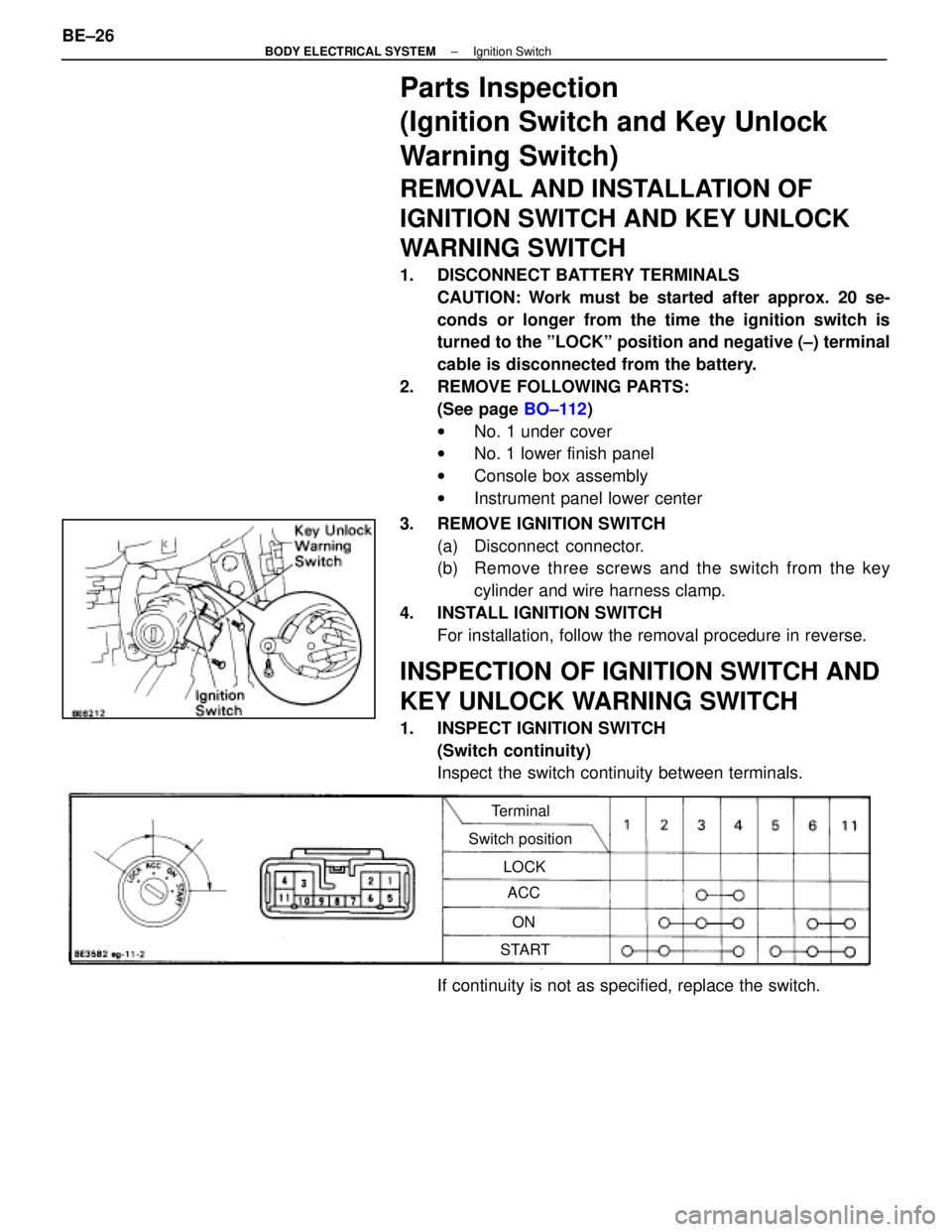
1. INSPECT IGNITION SWITCH(Switch continuity)
Inspect the switch continuity between terminals.
Terminal
Switch position LOCKACC
ON
START
If continuity is not as specified, replace the switch.
BE±26
±
BODY ELECTRICAL SYSTEM Ignition Switch
WhereEverybodyKnowsYourName
Page 823 of 4087

(Switch circuit)
Connect the switch connector and inspect the connector on
the wire harness side from the back side as shown.
Check forTester connectionConditionSpecified value
Voltage2±GroundIgnition switch turned to ONBattery voltage
3±GroundIgnition switch turned to ACC or ON
4±GroundConstant
5±GroundIgnition switch turned to START
6±GroundIgnition switch turned to ON
11±GroundConstant
If circuit is not as specified, inspect the switch or refer to
BE±25 wiring diagram and inspect the circuits connected to
other parts.
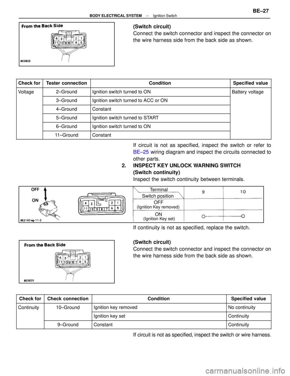
2. INSPECT KEY UNLOCK WARNING SWITCH
(Switch continuity)
Inspect the switch continuity between terminals.
Terminal
Switch position
ON
OFF
(Ignition Key removed)
(Ignition Key set)
If continuity is not as specified, replace the switch.
(Switch circuit)
Connect the switch connector and inspect the connector on
the wire harness side from the back side as shown.
Check forCheck connectionConditionSpecified value
Continuity10±GroundIgnition key removedNo continuity
Ignition key setContinuity
9±GroundConstantContinuity
If circuit is not as specified, inspect the switch or wire harness.
±
BODY ELECTRICAL SYSTEM Ignition SwitchBE±27
WhereEverybodyKnowsYourName
Page 826 of 4087
System Description ± Headlights
DAYTIME RUNNING LIGHT SYSTEM
The Daytime Running Light (DRL) system is activated when engine is started (However, if the parking brake
lever is engaged when the engine is started, the DRL will not light up a\
fter the engine has started. Once the
parking brake is released, the DRL will then light up and will remain on regardless of operation of\
the parking
brake lever).
The DRL remain on until the ignition switch is turned off.
BE±30±
BODY ELECTRICAL SYSTEM Lighting System
WhereEverybodyKnowsYourName
Page 827 of 4087
Operation example (Current flow table)
1. Daytime Running Light Lights Up
SwitchPosition
Ignition switchON (Engine running)
Light Control SwitchOFF
Headlight Dimmer SwitchLO or HI
Condition: Battery Voltage " (3) , (14)
2. Taillight Lights Up
SwitchPosition
Ignition SwitchOFF or ON
Light Control SwitchTAIL
Headlight Dimmer SwitchLO or HI
Condition: Battery Voltage " (3)
Continuity (16) " (17) " Ground
3. Headlight LO±Beam Lights Up
SwitchPosition
Ignition SwitchOFF or ON
Light Control SwitchHEAD
Headlight Dimmer SwitchLO
Condition: Battery Voltage " (3)
Continuity (16) " (17) " Ground
(18) " (17) " Ground
±
BODY ELECTRICAL SYSTEM Lighting SystemBE±31
WhereEverybodyKnowsYourName