Page 1153 of 4087
ABBREVIATIONS USED IN THIS MANUAL
For convenience, the following abbreviations are used in this
manual.
ABS Antilock Brake System
assy assembly
ECT Electronic Controlled Transmission
ECU Electronic Control Unit
e.g. Exempi Gratia (For Example)
Ex. Except
in. inch
LH Left-hand
MIG Metal Inert Gas
M/Y Model Year
PPS Progressive Power Steering
RH Right-hand
w/ with
w/o without
INTRODUCTIONIN-16
WhereEverybodyKnowsYourName
Page 1261 of 4087

Coolant which is heated in the water jacket is pumped to the radiator, through which a cooling fan blows
air to cool the coolant as it passes through. Coolant which has been coo\
led is then sent back to the engine by
the water pump, where it cools the engine. The water jacket is a network of channels in the shell of the cylinder bloc\
k and cylinderhead through which
coolant passes. It is designed to provide adequate cooling through the cylinders and combus\
tion chambers
which become heated during engine operation.
RADIATOR The radiator performs the function of cooling the coolant which has pass\
ed through the waterjacket and
become hot, and it is mounted in the front of the vehicle. The radiator consis\
ts of an upper tank and lower tank,
and a core which connects the two tanks. The upper tank contains the inlet \
for coolant from the water jacket
and the filler inlet. It also has a hose attached through which excess cool\
ant or steam can flow. The lower tank
contains the outlet for coolant and drain plug. The core contains many t\
ubes through which coolant flows from
the upper tank to the lower tank as well as cooling fins which radiate heat\
away from the coolant in the tubes.
The air sucked through the radiator by the cooling fan, as well as the wind generated by the ve\
hicle's travel,
passes through the radiator, cooling the coolant. Models with automatic transmission include an aut\
omatic
transmission fluid cooler built into the lower tank of the radiator. A cooling fan is mounted behind radiator to assist
the flow of air through the radiator. When the coolant temperature is low, the fan operates slowly to help the warm
up, and when the coolant temperature becomes high, the fan speed is increas\
ed to provide the air flow required
for cooling.
RADIATOR CAP (on Reservoir Tank)
The radiator cap is a pressure type cap which seals the radiator, resulting in pressurization of the radiator
as the coolant expands. The pressurization prevents the coolant from boi\
ling even when the coolant tempera-
ture exceeds 100 5C (212 5F). A relief valve (pressurization valve) and a vacuum valve (negati\
ve pressure valve)
are built into the radiator cap. The relief valve opens and lets steam esca\
pe through the overflow pipe when
the pressure generated inside the cooling system exceeds the limit (coolant temperature: 110±120 5C
(230±248 5F) pressure; 29.4±98.1 kPa (0.3±1.0 kgf/cm2, 4.3±14.2 psi)). The vacuum v\
alve opens to alleviate
the vacuum which develops in the coolant system after the engine is stopped\
and the coolant temperature
drops.
RESERVOIR TANK The purpose of the reservoir tank is to catch coolant overflows created by \
volumetrix expansion when the
coolant temperature increases. The cap of the reservoir tank is a pressure type\
which prevents deterioration
of the LLC (Long Life Coolant) caused by contact with atmospheric air, increases vaporization performance and
reduces loss of the coolant volume.
WATER PUMP The water pump is mounted on the front of the cylinder block and driven by t\
he reverse side of the timing
belt.
THERMOSTAT The thermostat has a wax type by±pass valve and is mounted in the wat\
er inlet housing. The thermostat
begins to open at the temperature of 80 5C (180 5F). When the coolant temperature is low, the valve closes to
prevent coolant flow to the radiator, thus permitting the engine to warm up rapidly. When the by±pass valve
opens the by±pass circuit, the engine coolant continues to circulate \
inside the engine, quickly and uniformly
warming up to the appropriate temperature. When the coolant temperature is high\
, the valve opens and coolant
flows to the radiator where it is cooled. When the wax inside the thermostat \
is heated, it expands and thus
creates pressure which overpowers the force of the spring which keeps the valve\
closed. When the wax cools,
its contraction causes the force of the spring to take effect once more, closing the valve.
ELECTRONICALLY CONTROLLED HYDRAULIC COOLING FAN (See page CO±22)
±
COOLIING SYSTEM DescriptionCO±3
WhereEverybodyKnowsYourName
Page 1282 of 4087
9. FILL ENGINE WITH COOLANT (See page CO±7)
10. FILL COOLING FAN RESERVOIR TANK WITH FLUID (See pages CO±23 and 24)
11. CHECK AUTOMATIC TRANSMISSION FLUID LEVEL
(See page MA±11)
NOTICE: Do not overfill.
12. START ENGINE AND CHECK FOR LEAKS
13. INSTALL ENGINE UNDER COVER
±
COOLIING SYSTEM RadiatorCO±21
WhereEverybodyKnowsYourName
Page 1283 of 4087

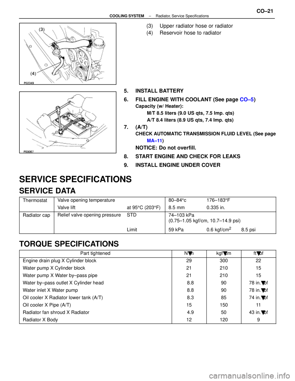
(3) Upper radiator hose or radiator
(4) Reservoir hose to radiator
5. INSTALL BATTERY
6. FILL ENGINE WITH COOLANT (See page CO±5)
Capacity (w/ Heater):
M/T 8.5 liters (9.0 US qts, 7.5 Imp. qts)
A/T 8.4 liters (8.9 US qts, 7.4 Imp. qts)
7. (A/T)
CHECK AUTOMATIC TRANSMISSION FLUID LEVEL (See pageMA±11 )
NOTICE: Do not overfill.
8. START ENGINE AND CHECK FOR LEAKS
9. INSTALL ENGINE UNDER COVER
SERVICE SPECIFICATIONS
SERVICE DATA
ThermostatValve opening temperature80±84 5c176±183 5F
Valve liftat 95 5C (203 5F) 8.5 mm0.335 in.
Radiator capRelief valve opening pressureSTD74±103 kPa
(0 75 1 05 k f/ 10 7 14 9 i)(0.75±1.05 kgf/cm, 10.7±14.9 psi)
Limit59 kPa0.6 kgf/cm28.5 psi
TORQUE SPECIFICATIONS
Part tightenedN �mkgf �cmft �lbf
Engine drain plug X Cylinder block2930022
Water pump X Cylinder block2121015
Water pump X Water by±pass pipe2121015
Water by±pass outlet X Cylinder head 8.89078 in. �lbf
Water inlet X Water pump 8.89078 in. �lbf
Oil cooler X Radiator lower tank (A/T) 8.38574 in. �lbf
Oil cooler X Pipe (A/T)1515011
Radiator fan shroud X Radiator 4.95043 in. �lbf
Radiator X Body121209
±
COOLING SYSTEM Radiator, Service SpecificationsCO±21
WhereEverybodyKnowsYourName
Page 1329 of 4087

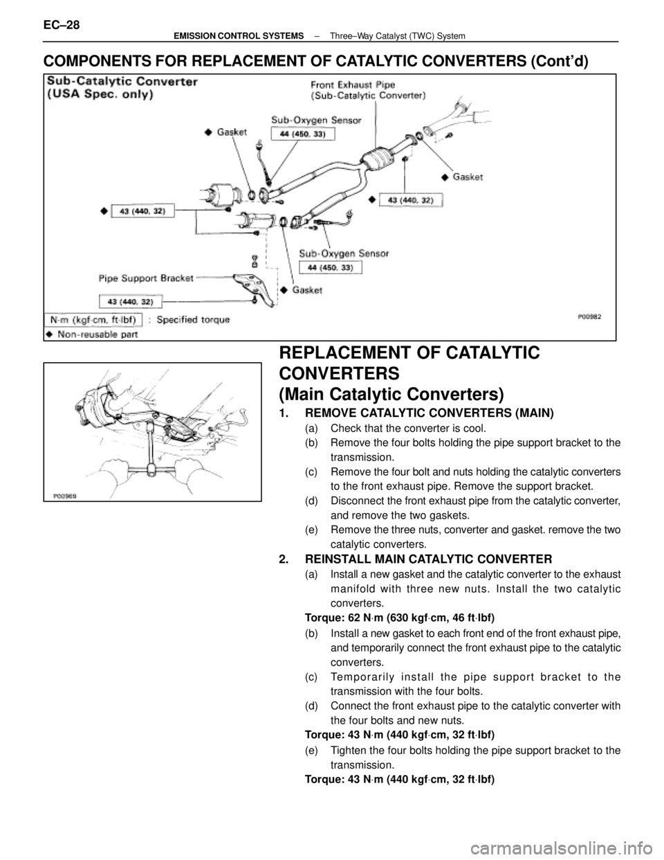
COMPONENTS FOR REPLACEMENT OF CATALYTIC CONVERTERS (Cont'd)
REPLACEMENT OF CATALYTIC
CONVERTERS
(Main Catalytic Converters)
1. REMOVE CATALYTIC CONVERTERS (MAIN)
(a) Check that the converter is cool.
(b) Remove the four bolts holding the pipe support bracket to thetransmission.
(c) Remove the four bolt and nuts holding the catalytic converters
to the front exhaust pipe. Remove the support bracket.
(d) Disconnect the front exhaust pipe from the catalytic converter,
and remove the two gaskets.
(e) Remove the three nuts, converter and gasket. remove the two
catalytic converters.
2. REINSTALL MAIN CATALYTIC CONVERTER
(a) Install a new gasket and the catalytic converter to the exhaust manifold with three new nuts. Install the two catalytic
converters.
Torque: 62 N Vm (630 kgf Vcm, 46 ft Vlbf)
(b) Install a new gasket to each front end of the front exhaust pipe,
and temporarily connect the front exhaust pipe to the catalytic
converters.
(c) Temporarily install the pipe support bracket to the transmission with the four bolts.
(d) Connect the front exhaust pipe to the catalytic converter with the four bolts and new nuts.
Torque: 43 N Vm (440 kgf Vcm, 32 ft Vlbf)
(e) Tighten the four bolts holding the pipe support bracket to the transmission.
Torque: 43 N Vm (440 kgf Vcm, 32 ft Vlbf)
EC±28±
EMISSION CONTROL SYSTEMS Three±Way Catalyst (TWC) System
WhereEverybodyKnowsYourName
Page 1330 of 4087

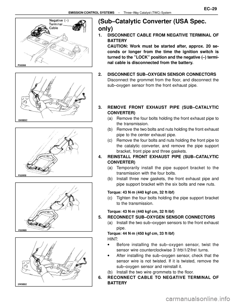
(Sub±Catalytic Converter (USA Spec.
only)
1. DISCONNECT CABLE FROM NEGATIVE TERMINAL OFBATTERY
CAUTION: Work must be started after, approx. 20 se-
conds or longer from the time the ignition switch is
turned to the ºLOCKº position and the negative (±) termi-
nal cable is disconnected from the battery.
2. DISCONNECT SUB±OXYGEN SENSOR CONNECTORS Disconnect the grommet from the floor, and disconnect the
sub±oxygen sensor from the front exhaust pipe.
3. REMOVE FRONT EXHAUST PIPE (SUB±CATALYTIC CONVERTER)
(a) Remove the four bolts holding the front exhaust pipe tothe transmission.
(b) Remove the two bolts and nuts holding the front exhaust
pipe to the center exhaust pipe.
(c) Remove the four bolts and nuts holding the front pipe to the catalytic converter, and remove the pipe support
bracket, front pipe and three gaskets.
4. REINSTALL FRONT EXHAUST PIPE (SUB±CATALYTIC CONVERTER)
(a) Temporarily install the pipe support bracket to thetransmission with the four bolts.
(b) Install three new gaskets, the front exhaust pipe and pipe support bracket with the six bolts and new nuts.
Torque: 43 N Vm (440 kgf Vcm, 32 ft Vlbf)
(c) Tighten the four bolts holding the pipe support bracket
to the transmission.
Torque: 43 N Vm (440 kgf Vcm, 32 ft Vlbf)
5. RECONNECT SUB±OXYGEN SENSOR CONNECTORS
(a) Install the two sub±oxygen sensors to the front exhaustpipe.
Torque: 44 N Vm (450 kgf Vcm, 33 ft Vlbf)
HINT:
w Before installing the s ub±oxygen sensor, twist the
sensor wire counterclockwise 3 \frb\1/2\fre turns.
w After installing the sub±oxygen sensor, check that the
sensor wire is not twisted. If it is twisted, remove the
sub±oxygen sensor and reinstall it.
(b) Install the two wire grommets to the floor.
6. RECONNECT CABLE TO NEGATIVE TERMINAL OF
BATTERY
±
EMISSION CONTROL SYSTEMS Three±Way Catalyst (TWC) SystemEC±29
WhereEverybodyKnowsYourName
Page 1331 of 4087
SERVICE SPECIFICATIONS
SERVICE DATA
VSVResistance30±34 �
for EVAP
VSVResistance33±39 �
for EGR
EGR valveResistance19.9±23.4 �
(CALIF. only)
TORQUE SPECIFICATIONS
Part tightenedNVmkgf Vcmft Vlbf
VSV for EGR X Air intake chamber (Exc. USA Spec.)1818513
EGR valve X Air intake chamber18185 13
Catalytic converter (Main) X Exhaust manifold62630 46
Catalytic converter (Main) X Front exhaust pipe43440 32
Front exhaust pipe support bracket X Transmission43440 32
Front exhaust pipe X Center exhaust pipe43440 32
Main oxygen sensor X Front exhaust pipe4445033
EC±30±
EMISSION CONTROL SYSTEMS Servuce Specifications
WhereEverybodyKnowsYourName
Page 1350 of 4087
INSPECTION OF EGR SYSTEM
1. CHECK AND CLEAN FILTER IN EGR VACUUMMODULATOR
(a) Remove the cap and filter.
(b) Check the filter for contamination or damage.
(c) Using compressed air, clean the filter.
(d) Reinstall the filter and cap.
HINT: Install the filter with the coarser surface facing the at-
mospheric side (out ward).
2. INSPECT SYSTEM OPERATION (a) Connect the tachometer to terminal IG ± of the check(ºDIAGNOSISº) connector.
(b) Using SST connect the terminals TE1 and E1 of the check (ºDIAGNOSISº) connector.
SST 09843±18020
(c) Keep the engine at 3,500 rpm with the transmission in ºNº position.
(d) Remove the SST from the check connector.
SST 09843±18020
EC±12
±
EMISSION CONTROL SYSTEMS Exhaust Gas Recirculation (EGR) System
WhereEverybodyKnowsYourName