Page 3017 of 4087
POWER STEERING ECU
1. JACK UP VEHICLE AND SUPPORT IT ON STANDS
2. START ENGINE
3. MEASURE VOLTAGE OF ECU
(a) Using a voltmeter, measure the voltage between ECUterminals SOL � and GND while the engine is idling.
Standard voltage:
0.3±0.5 V
(b) Place the transmission in gear and while running at about 37
mph (60 km/h), measure the voltage between ECU terminals
SOL � and GND.
Standard voltage:
Voltage measured in (a) above, minus
(IUZ±FE Engine)
0.07±0.02 V
(2JZ±FE Engine)
0.05±0.18 V
If no voltage, try another ECU.
4. LOWER VEHICLE
SR±168
±
STEERING POWER STEERING
WhereEverybodyKnowsYourName
Page 3076 of 4087
LOCATION OF CONNECTORS
LOCATION OF CONNECTORS IN ENGINE COMPARTMENT
SC400
SR±54±
STEERING STEERING COLUMN
WhereEverybodyKnowsYourName
Page 3147 of 4087

1. DISCONNECT NEGATIVE (±) TERMINAL CABLE FROMBATTERY
CAUTION: Work must be started after 90 seconds from
the time the ignition switch is turned to the ªLOCKº posi-
tion and the negative (±) terminal cable is disconnected
from the battery.
(See page RS±2)
2. REMOVE ENGINE UNDER COVER
(See page BO±12)
3. REMOVE FRONT AIRBAG SENSOR
(a) Disconnect the connector.
(b) Remove the bolt, the nut and the sensor.
4. INSTALL FRONT AIRBAG SENSOR
(a) Install the sensor with the arrow on the sensor facing toward the front of the vehicle.
Torque: 25 N Vm (260 kgf Vcm, 19 ft Vlbf)
NOTICE:
w Make sure the sensor is installed to the specified torque.
w If the sensor has been dropped, or there are cracks, dents
or other defects in the case, brackets or c onnector,
replace the sensor is removed, always replace the set bolt
and the nut with new one.
w The sensor set bolt and the nut have been anti±rust
treated. When the sensor is removed, always replace the
set bolt and the nut with new ones.
w After installation, shake the sensor to check that there is
no looseness.
w The front sensor is equipped with an electrical
connection check mechanism. Be sure to lock this
mechanism securely when connecting the connector. If
the connector is not securely locked, a malfunction code
will be detected by the diagnosis system.
w Check that the dimensions of the body where the front
airbag sensor is installed match those in the body
dimension drawings in the BODY section.
(The SRS may malfunction, or may not work, if the
dimensions of the sensor mount is not correct.)
5. INSTALL ENGINE UNDER COVER
6. CONNECT NEGATIVE (±) TERMINAL CABLE TO BATTERY
±
SUPPLEMENTAL RESTRAINT SYSTEM FRONT AIRBAG SENSORRS±43
WhereEverybodyKnowsYourName
Page 3173 of 4087

YESNO
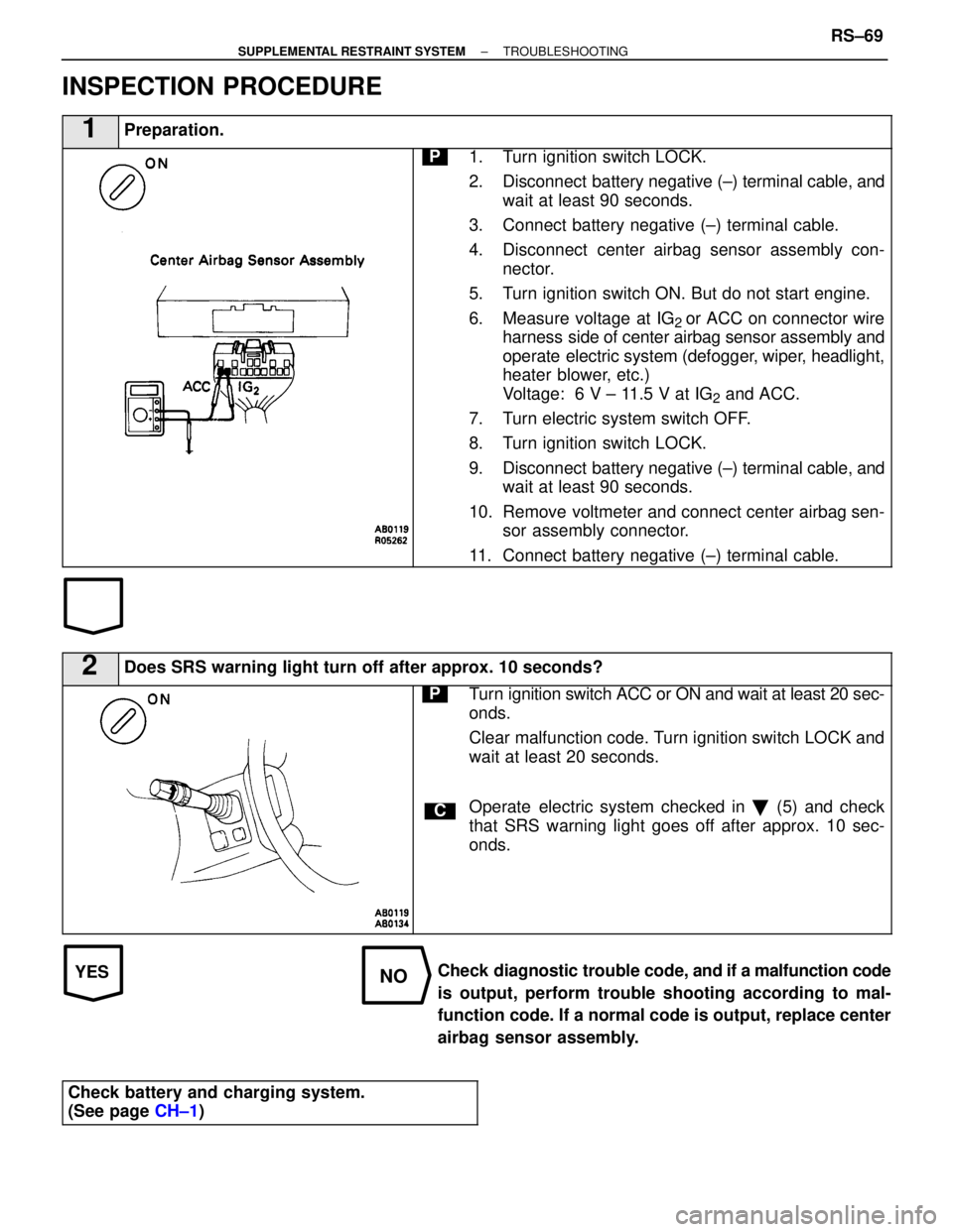
INSPECTION PROCEDURE
1Preparation.
P1. Turn ignition switch LOCK.
2. Disconnect battery negative (±) terminal cable, andwait at least 90 seconds.
3. Connect battery negative (±) terminal cable.
4. Disconnect center airbag sensor assembly con- nector.
5. Turn ignition switch ON. But do not start engine.
6. Measure voltage at IG
2 or ACC on connector wire
harness side of center airbag sensor assembly and
operate electric system (defogger, wiper, headlight,
heater blower, etc.)
Voltage: 6 V ± 11.5 V at IG
2 and ACC.
7. Turn electric system switch OFF.
8. Turn ignition switch LOCK.
9. Disconnect battery negative (±) terminal cable, and wait at least 90 seconds.
10. Remove voltmeter and connect center airbag sen- sor assembly connector.
11. Connect battery negative (±) terminal cable.
2Does SRS warning light turn off after approx. 10 seconds?
C
PTurn ignition switch ACC or ON and wait at least 20 sec-
onds.
Clear malfunction code. Turn ignition switch LOCK and
wait at least 20 seconds.
Operate electric system checked in � (5) and check
that SRS warning light goes off after approx. 10 sec-
onds.
Check diagnostic trouble code, and if a malfunction code
is output, perform trouble shooting according to mal-
function code. If a normal code is output, replace center
airbag sensor assembly.
Check battery and charging system.
(See page CH±1)
±
SUPPLEMENTAL RESTRAINT SYSTEM TROUBLESHOOTINGRS±69
WhereEverybodyKnowsYourName
Page 3217 of 4087
2. CONNECT REAR DRIVE SHAFTS
(a) Align the matchmarks on the side gear shaft and drive shafts.
(b) Apply a light coat of engine oil on the threads of the bolts.
(c) Temporarily install the 12 hexagon bolts and 4 washers.
(d) Using a hexagon wrench, torque the bolts.
Torque: 83 N Vm (850 kgf Vcm, 61 ft Vlbf)
3. INSTALL PROPELLER SHAFT
(See page PR±12 or 28)
4. FILL DIFFERENTIAL WITH OIL
Oil grade: API GL±5 Hypoid Gear Oil
Viscosity: Above±18 �C (0 �F) SAE 90
Below±18 �C (0 �F) SAE 80W±90 or 80W
Capacity:
1.35 liters (1.42 US qts, 1.19 lmp qts)
SA±84±
SUSPENSION AND AXLE REAR DIFFERENTIAL
WhereEverybodyKnowsYourName
Page 3269 of 4087

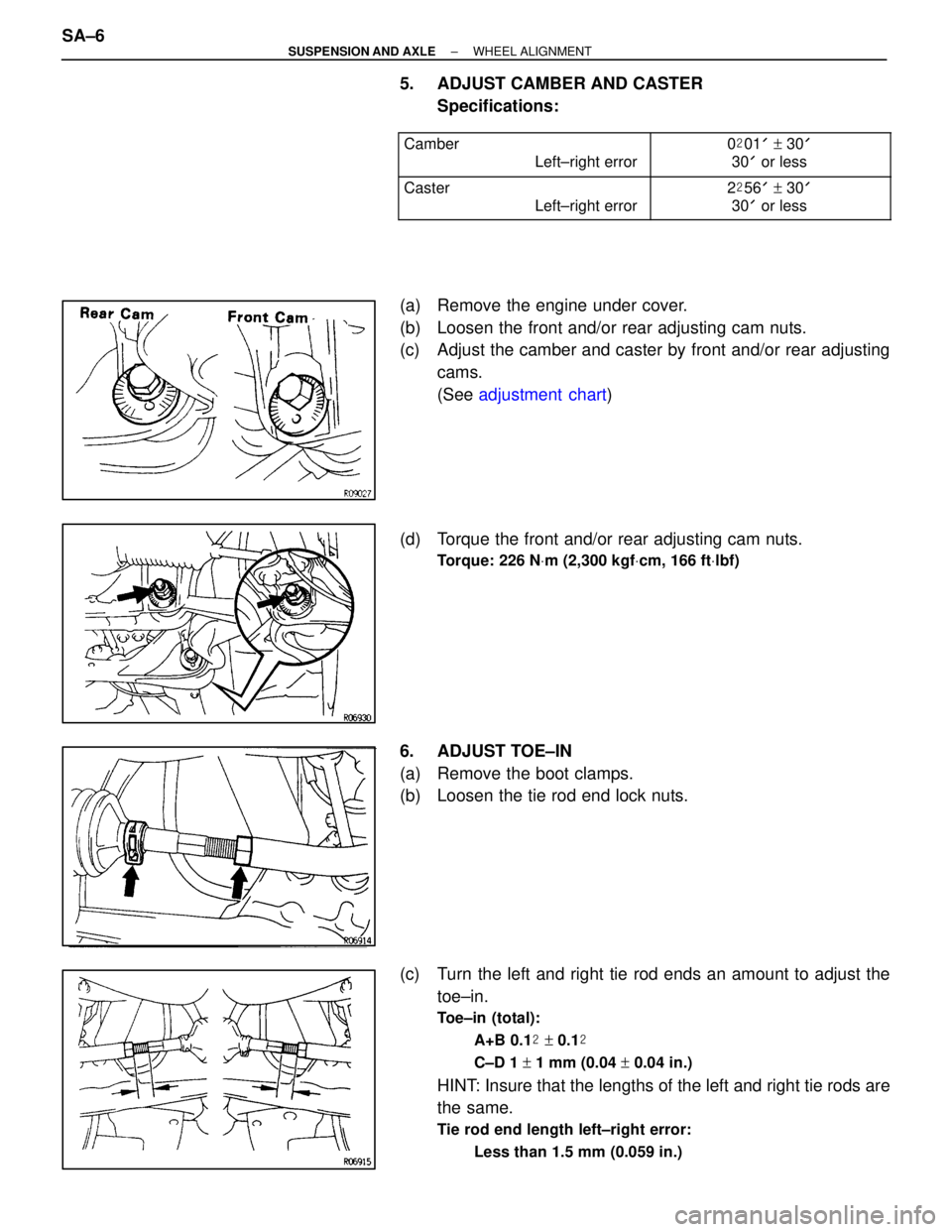
5. ADJUST CAMBER AND CASTERSpecifications:
������������ �
�����������
������������
Camber
Left±right error����������� �
����������
�����������
0
�01 ' + 30 '
30 ' or less
������������ �
�����������
������������
Caster
Left±right error����������� �
����������
�����������
2
�56 ' + 30 '
30 ' or less
(a) Remove the engine under cover.
(b) Loosen the front and/or rear adjusting cam nuts.
(c) Adjust the camber and caster by front and/or rear adjusting
cams.
(See adjustment chart )
(d) Torque the front and/or rear adjusting cam nuts.
Torque: 226 N Vm (2,300 kgf Vcm, 166 ft Vlbf)
6. ADJUST TOE±IN
(a) Remove the boot clamps.
(b) Loosen the tie rod end lock nuts.
(c) Turn the left and right tie rod ends an amount to adjust the
toe±in.
Toe±in (total):
A+B 0.1 � + 0.1 �
C±D 1 + 1 mm (0.04 + 0.04 in.)
HINT: Insure that the lengths of the left and right tie rods are
the same.
Tie rod end length left±right error:
Less than 1.5 mm (0.059 in.)
SA±6±
SUSPENSION AND AXLE WHEEL ALIGNMENT
WhereEverybodyKnowsYourName
Page 3304 of 4087
LOWER SUSPENSION ARM REMOVAL
SA1A4±01
1. JACK UP VEHICLE AND REMOVE FRONT WHEEL
2. REMOVE ENGINE UNDER COVER
3. REMOVE FRONT BRAKE CALIPER
(b) Hang up the brake caliper using wire, etc.
4. DISCONNECT STABILIZER BAR LINK FROM LOWERSUSPENSION ARM
Remove the nut and disconnect the link from the arm.
5. DISCONNECT STEERING KNUCKLE
(a) Remove the clip and nut.
(b) Using SST, disconnect the steering knuckle from the lower suspension arm.
SST 09628±62011
6. REMOVE LOWER SUSPENSION ARM
(a) R e m o v e t h e b o l t a n d n u t a n d d i s c onnect the lower
suspension arm from the shock absorber.
±
SUSPENSION AND AXLE FRONT SUSPENSIONSA±41
WhereEverybodyKnowsYourName
Page 3307 of 4087
3. INSTALL BRAKE CALIPERInstall the brake caliper to the steering cnuckle with the 2
bolts.
Torque: 118 N Vm (1,200 kgf Vcm, 87 ft Vlbf)
4. STABILIZE SUSPENSION
(a) Install the front wheel and jack down the vehicle.
Torque: 103 N Vm (1,050 kgf Vcm, 76 ft Vlbf)
(b) Bounce the vehicle up and down several times to stabilize the
suspension.
5. TORQUE ADJUSTING CAMS AND NUTS
(a) Jack up the vehicle and remove the front wheel.
(b) Support the lower arm with jack.
(c) Align the matchmarks and torque the adjusting cams and nuts with the vehicle weight on the suspension.
Torque: 226 N Vm (2,300 kgf Vcm, 166 ft Vlbf)
6. INSTALL ENGINE UNDER COVER
7. INSTALL FRONT WHEEL
Torque: 103 N Vm (1,050 kgf Vcm, 76 ft Vlbf)
8. CHECK FRONT WHEEL ALIGNMENT
(See page SA±5)
SA±44
±
SUSPENSION AND AXLE FRONT SUSPENSION
WhereEverybodyKnowsYourName