Page 2753 of 4087
Fuel Pressure Control VSV Circuit
CIRCUIT DESCRIPTION
The ECU turns on a VSV (Vacuum Switching Valve)
to draw the air into the diaphragm chamber of the
pressure regulator if it detects that the temperature of
the coolant is too high during engine starting.
The air drawn into the chamber increases the fuel
pressure to prevent fuel vapor lock at high engine
temperature in order to help the engine start when it
is warm.
Fuel pressure control ends approx. 100 secs. after
the engine is started.
DIAGNOSTIC CHARTDIAGNOSTIC CHART
Check operation for fuel pressure control
VSV.Replace fuel pressure control VSV.
Repair or replace harness or
connector.
Proceed to next circuit inspection
shown on matrix chart (See page
TR±35).
Check for open and short in harness and
connector between main relay and ECU.
Check voltage of VSV power source.
Check and replace ECU.
WIRING DIAGRAM
TR±142±
ENGINE TROUBLESHOOTING Circuit Inspection
WhereEverybodyKnowsYourName
Page 2755 of 4087
NGOK
OKNG
2Check voltage between terminal FPU of engine & ECT ECU connector and body gro\
und.
C
OK
Hint
P(2) Connect the Check Harness A.(See page TR±30)
(2) Turn ignition switch on.
Measure voltage between terminal FPU of engine &
ECT ECU connector and body ground.
Voltage: 10 ± 14 V
Proceed to next circuit inspection shown on matrix chart
(See page TR±35).
3
Check for open and short in harness and connector between engine & ECT ECU an\
d VSV, VSV
and EFI main relay (See page IN±27).
Repair or replace harness or connector
Check and replace engine & ECT ECU.
TR±144±
ENGINE TROUBLESHOOTING Circuit Inspection
WhereEverybodyKnowsYourName
Page 2759 of 4087

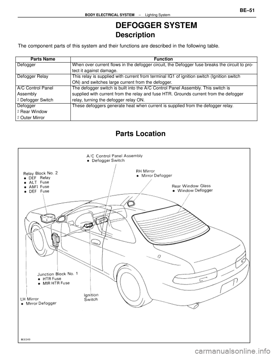
DEFOGGER SYSTEM
Description
The component parts of this system and their functions are described in the\
following table.
��������� ���������Parts Name������������������\
���������� ������������������\
����������Function
��������� ���������Defogger������������������\
���������� ������������������\
����������When over current flows in the defogger circuit, the Defogger fuse break\
s the circuit to pro-
tect it against damage.
��������� �
��������
���������
Defogger Relay������������������\
���������� �
������������������\
���������
������������������\
����������
This relay is supplied with current from terminal IG1 of ignition switch\
(Ignition switch
ON) and switches large current from the defogger.
��������� �
��������
���������
A/C Control Panel
Assembly
�
Defogger Switch������������������\
���������� �
������������������\
���������
������������������\
����������
The defogger switch is built into the A/C Control Panel Assembly. This switch is
supplied with current from the relay and fuse HTR. Grounds current from \
the defogger
relay, turning the defogger relay ON.
��������� �
��������
�
��������
���������
Defogger
�
Rear Window
� Outer Mirror������������������\
���������� �
������������������\
���������
�
������������������\
���������
������������������\
����������
These defoggers generate heat when current is supplied from the defogger\
relay.
Parts Location
±
BODY ELECTRICAL SYSTEM Lighting SystemBE±51
WhereEverybodyKnowsYourName
Page 2761 of 4087

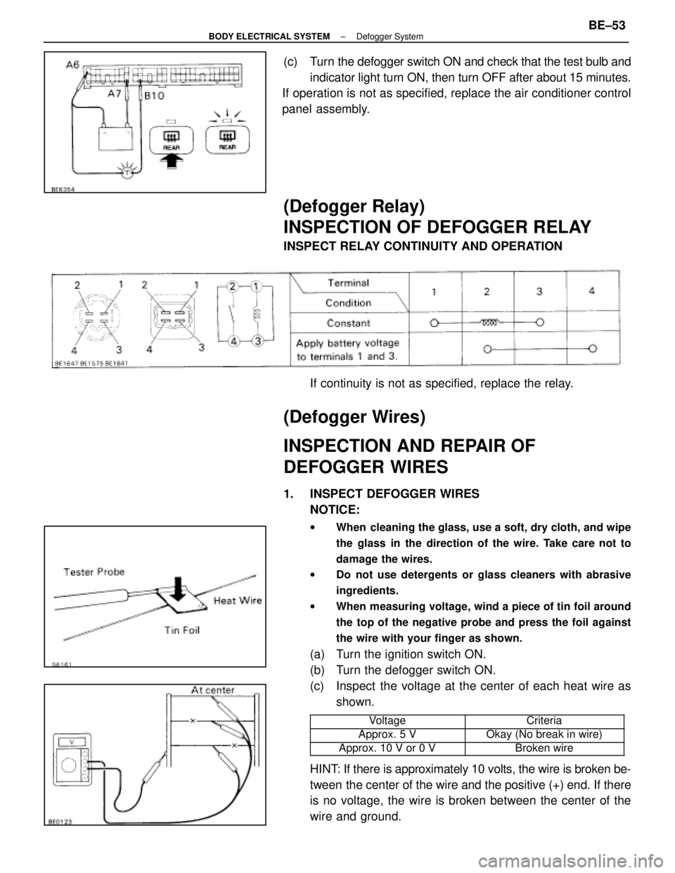
(c) Turn the defogger switch ON and check that the test bulb andindicator light turn ON, then turn OFF after about 15 minutes.
If operation is not as specified, replace the air conditioner control
panel assembly.
(Defogger Relay)
INSPECTION OF DEFOGGER RELAY
INSPECT RELAY CONTINUITY AND OPERATION
If continuity is not as specified, replace the relay.
(Defogger Wires)
INSPECTION AND REPAIR OF
DEFOGGER WIRES
1. INSPECT DEFOGGER WIRESNOTICE:
w When cleaning the glass, use a soft, dry cloth, and wipe
the glass in the direction of the wire. Take care not to
damage the wires.
w Do not use detergents or glass cleaners with abrasive
ingredients.
w When measuring voltage, wind a piece of tin foil around
the top of the negative probe and press the foil against
the wire with your finger as shown.
(a) Turn the ignition switch ON.
(b) Turn the defogger switch ON.
(c) Inspect the voltage at the center of each heat wire as
shown.
���������� ����������Voltage���������� ����������Criteria
����������Approx. 5 V����������Okay (No break in wire)���������� ����������Approx. 10 V or 0 V���������� ����������Broken wire
HINT: If there is approximately 10 volts, the wire is broken be-
tween the center of the wire and the positive (+) end. If there
is no voltage, the wire is broken between the center of the
wire and ground.
±
BODY ELECTRICAL SYSTEM Defogger SystemBE±53
WhereEverybodyKnowsYourName
Page 2925 of 4087
STARTER RELAY
INSPECTION OF STARTER RELAY
(See page ST±2)
1. INSPECT RELAY CONTINUITY (a) Using an ohmmeter, check that there is continuity
between terminals 1 and 2.
(b) Check that there is no continuity between terminals 3 and 5.
If continuity is not as specified, replace the relay.
2. INSPECT RELAY OPERATION (a) Apply battery voltage across terminals 1 and 2.
(b) Using an ohmmeter, check that there is continuitybetween terminals 3 and 5.
If operation is not as specified, replace the relay.
NEUTRAL START SWITCH
(See AT section)
THEFT DETERRENT SYSTEM
(See BE Section)
ST±14
±
STARTING SYSTEM Starter Relay
WhereEverybodyKnowsYourName
Page 2927 of 4087

STARTER RELAY
INSPECTION OF STARTER RELAY
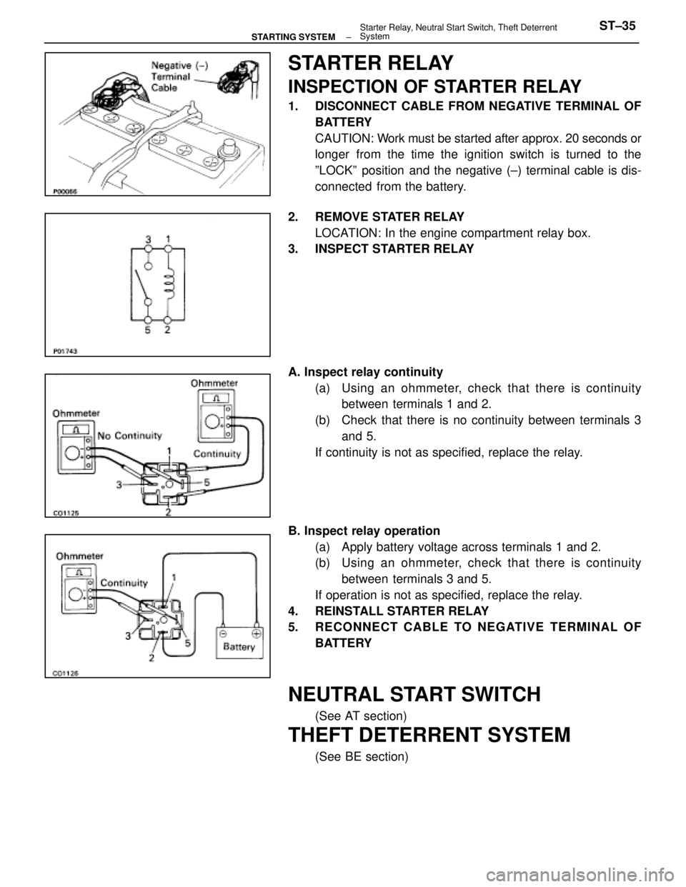
1. DISCONNECT CABLE FROM NEGATIVE TERMINAL OFBATTERY
CAUTION: Work must be started after approx. 20 seconds or
longer from the time the ignition switch is turned to the
ºLOCKº position and the negative (±) terminal cable is dis-
connected from the battery.
2. REMOVE STATER RELAY LOCATION: In the engine compartment relay box.
3. INSPECT STARTER RELAY
A. Inspect relay continuity
(a) Using an ohmmeter, check that there is continuitybetween terminals 1 and 2.
(b) Check that there is no continuity between terminals 3 and 5.
If continuity is not as specified, replace the relay.
B. Inspect relay operation (a) Apply battery voltage across terminals 1 and 2.
(b) Using an ohmmeter, check that there is continuitybetween terminals 3 and 5.
If operation is not as specified, replace the relay.
4. REINSTALL STARTER RELAY
5. RECONNECT CABLE TO NEGATIVE TERMINAL OF BATTERY
NEUTRAL START SWITCH
(See AT section)
THEFT DETERRENT SYSTEM
(See BE section)
±
STARTING SYSTEM Starter Relay, Neutral Start Switch, Theft Deterrent
SystemST±35
WhereEverybodyKnowsYourName
Page 3344 of 4087
ECU Power Source Circuit
CIRCUIT DESCRIPTION
When the ignition switch is turned on, battery voltage
is applied to the terminal IG SW of the ECU, and the
main relay control circuit in the ECU sends a signal to
the terminal M±REL of the ECU, switching on the
main relay. This signal causes current to flow to the
coil, closing the contacts of the main relay and supply-
ing power to the terminals +B and +B1 of the ECU.
If the ignition switch is turned off, the ECU continues
to switch on the main relay for a maximum of 2 se-
conds for the initial setting of the ISC valve.
DIAGNOSTIC CHARTDIAGNOSTIC CHART
See next page for the DIAGNOSTIC CHART.
WIRING DIAGRAM
TR±124±
ENGINE TROUBLESHOOTING Circuit Inspection
WhereEverybodyKnowsYourName
Page 3345 of 4087
DIAGNOSTIC CHART
DIAGNOSTIC
CHART
Check for short in all the harness and
components connected to IGN fuse.
Check voltage of terminal M±REL.
Check for open in harness and connector
between battery and ECU.
Check and replace ECU.
Replace ignition switch.
Repair or replace harness or
connector.
Repair or replace harness or
connector.
Check for open and short in harness and
connector between terminal M REL and body
ground.
Replace EFT main relay.
Check voltage of terminal IGSW.
Check IGN fuse.
Check continuity between terminals E1 and
body ground.
Check voltage of ECU power source.
Proceed to next circuit inspection
shown on matrix chart (See page
TR±35
).
Check ignition switch.
Check EFT fuse.
Check EFT main relay.
Check and repair or harness or connector
between EFI fuse and battery.
Check for short in all the harness and
components connected to EFI fuse.
±
ENGINE TROUBLESHOOTING Circuit InspectionTR±125
WhereEverybodyKnowsYourName