Page 537 of 4087

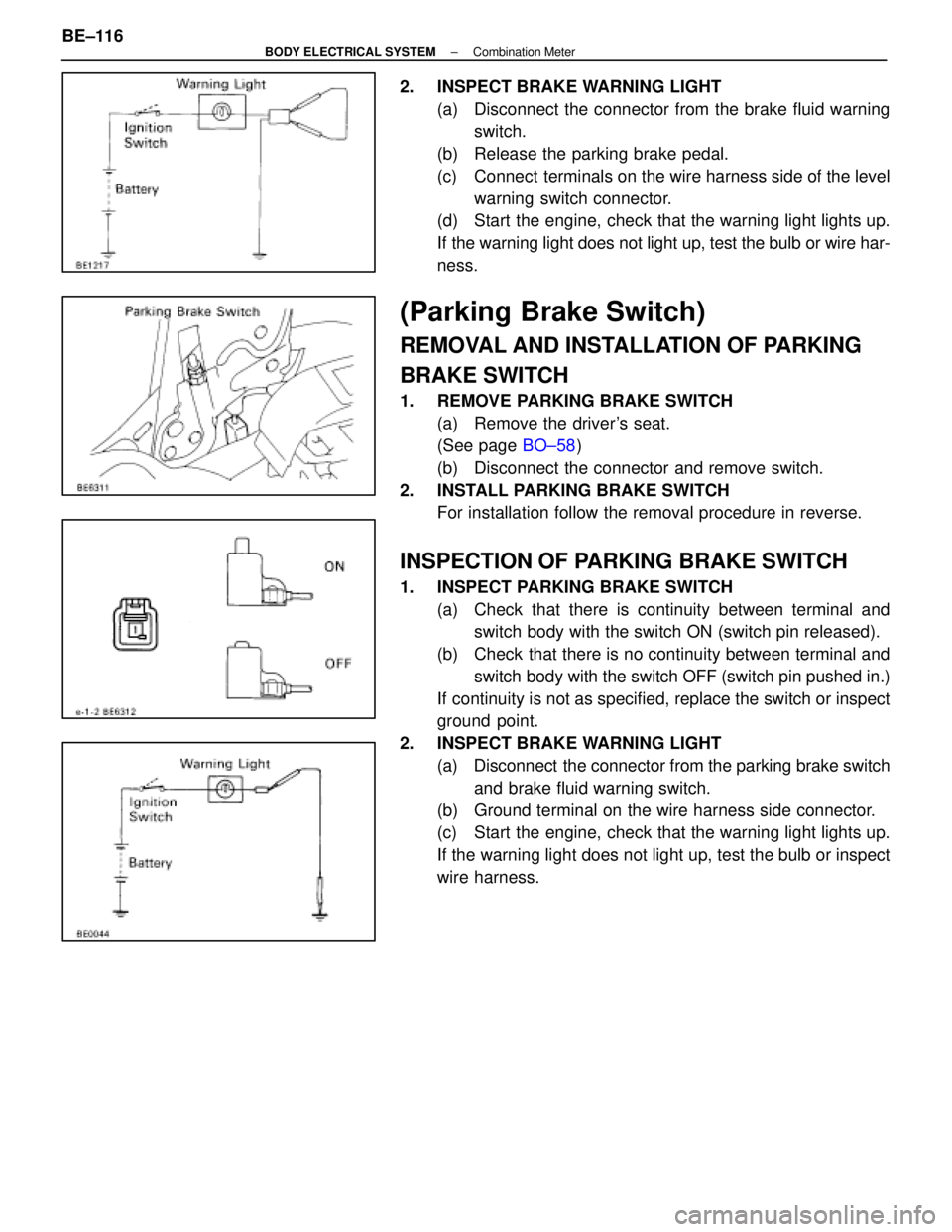
2. INSPECT BRAKE WARNING LIGHT(a) Disconnect the connector from the brake fluid warningswitch.
(b) Release the parking brake pedal.
(c) Connect terminals on the wire harness side of the level warning switch connector.
(d) Start the engine, check that the warning light lights up.
If the warning light does not light up, test the bulb or wire har-
ness.
(Parking Brake Switch)
REMOVAL AND INSTALLATION OF PARKING
BRAKE SWITCH
1. REMOVE PARKING BRAKE SWITCH
(a) Remove the driver's seat.
(See page BO±58)
(b) Disconnect the connector and remove switch.
2. INSTALL PARKING BRAKE SWITCH For installation follow the removal procedure in reverse.
INSPECTION OF PARKING BRAKE SWITCH
1. INSPECT PARKING BRAKE SWITCH
(a) Check that there is continuity between terminal andswitch body with the switch ON (switch pin released).
(b) Check that there is no continuity between terminal and switch body with the switch OFF (switch pin pushed in.)
If continuity is not as specified, replace the switch or inspect
ground point.
2. INSPECT BRAKE WARNING LIGHT (a) Disconnect the connector from the parking brake switchand brake fluid warning switch.
(b) Ground terminal on the wire harness side connector.
(c) Start the engine, check that the warning light lights up.
If the warning light does not light up, test the bulb or inspect
wire harness.
BE±116
±
BODY ELECTRICAL SYSTEM Combination Meter
WhereEverybodyKnowsYourName
Page 538 of 4087

( Coolant Level Warning Switch)
REMOVAL AND INSTALLATION OF COOLANT
LEVEL WARNING SWITCH
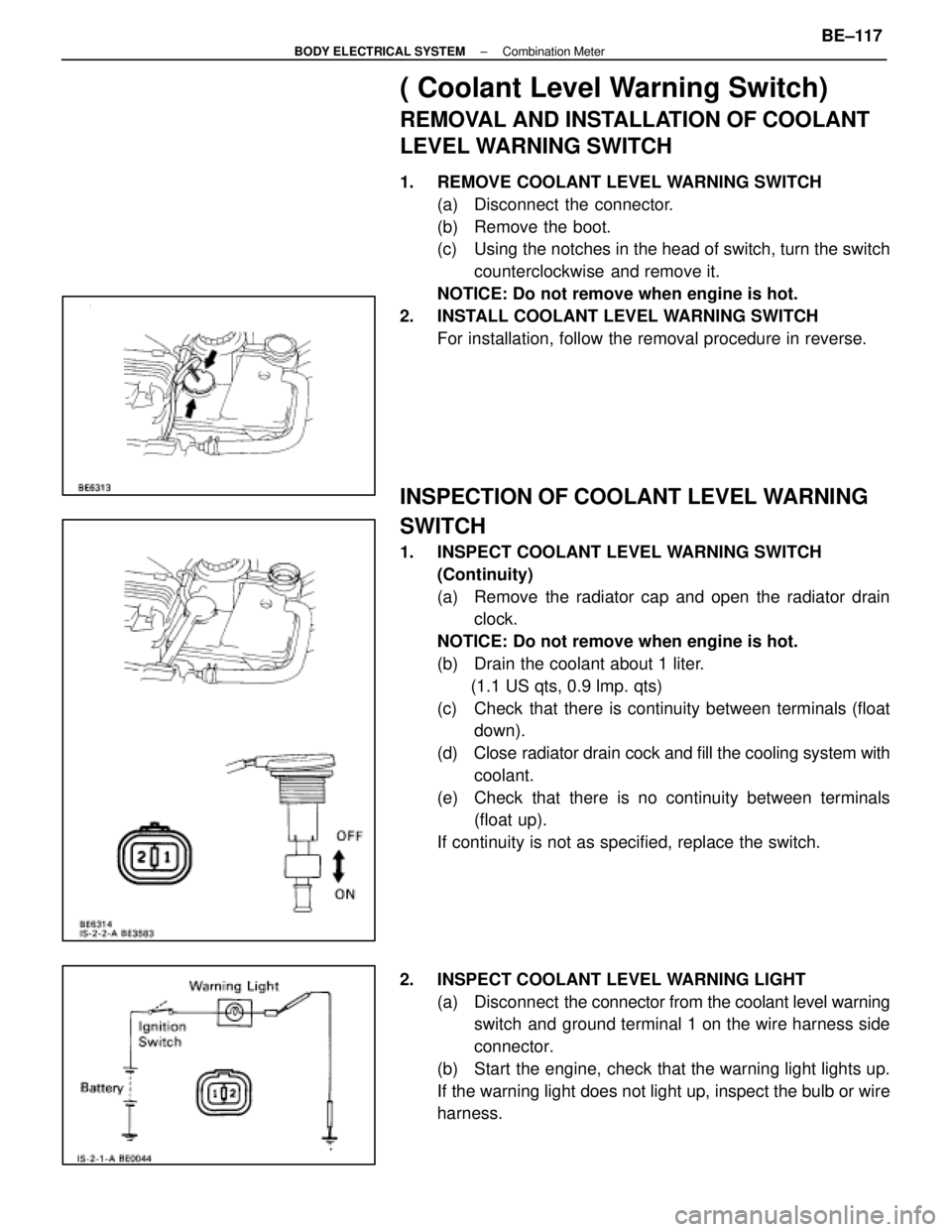
1. REMOVE COOLANT LEVEL WARNING SWITCH(a) Disconnect the connector.
(b) Remove the boot.
(c) Using the notches in the head of switch, turn the switchcounterclockwise and remove it.
NOTICE: Do not remove when engine is hot.
2. INSTALL COOLANT LEVEL WARNING SWITCH For installation, follow the removal procedure in reverse.
INSPECTION OF COOLANT LEVEL WARNING
SWITCH
1. INSPECT COOLANT LEVEL WARNING SWITCH(Continuity)
(a) Remove the radiator cap and open the radiator drainclock.
NOTICE: Do not remove when engine is hot.
(b) Drain the coolant about 1 liter. (1.1 US qts, 0.9 lmp. qts)
(c) Check that there is continuity between terminals (float down).
(d) Close radiator drain cock and fill the cooling system with
coolant.
(e) Check that there is no continuity between terminals (float up).
If continuity is not as specified, replace the switch.
2. INSPECT COOLANT LEVEL WARNING LIGHT (a) Disconnect the connector from the coolant level warning
switch and ground terminal 1 on the wire harness side
connector.
(b) Start the engine, check that the warning light lights up.
If the warning light does not light up, inspect the bulb or wire
harness.
±
BODY ELECTRICAL SYSTEM Combination MeterBE±117
WhereEverybodyKnowsYourName
Page 605 of 4087

����� �����
������������������\
��������� ������������������\
���������
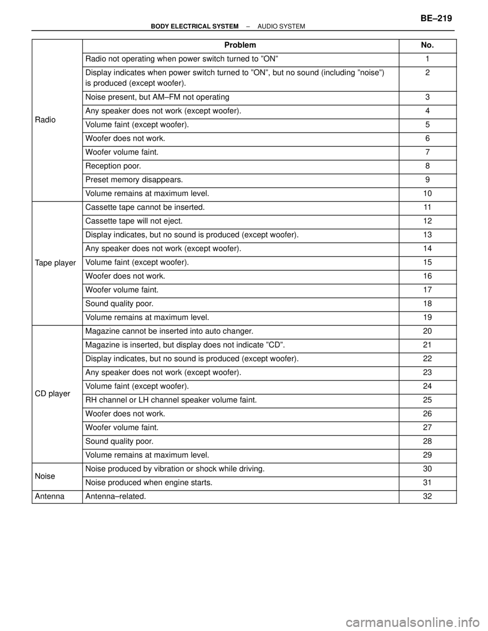
Problem������ ������No.
����� �����������������������\
��������� ������������������\
���������Radio not operating when power switch turned to ºONº������ ������1
����� �
����
�����
������������������\
��������� �
������������������\
��������
������������������\
���������
Display indicates when power switch turned to ºONº, but no sound (\
including ºnoiseº)
is produced (except woofer).������ �
�����
������
2
����� �����������������������\
��������� ������������������\
���������Noise present, but AM±FM not operating������ ������3
����� �����
Radio
������������������\
��������� ������������������\
���������Any speaker does not work (except woofer).������ ������4
����� �����Radio������������������\
��������� ������������������\
���������Volume faint (except woofer).������ ������5����� �����������������������\
��������� ������������������\
���������Woofer does not work.������ ������6����� �
����
�����
������������������\
��������� �
������������������\
��������
������������������\
���������Woofer volume faint.������ �
�����
������7
����� �����������������������\
��������� ������������������\
���������Reception poor.������ ������8
����� �����������������������\
��������� ������������������\
���������Preset memory disappears.������ ������9
����� �����������������������\
��������� ������������������\
���������Volume remains at maximum level.������ ������10
����� �����������������������\
��������� ������������������\
���������Cassette tape cannot be inserted.������ ������11
����� �����������������������\
��������� ������������������\
���������Cassette tape will not eject.������ ������12
����� �����������������������\
��������� ������������������\
���������Display indicates, but no sound is produced (except woofer).������ ������13����� �����������������������\
��������� ������������������\
���������Any speaker does not work (except woofer).������ ������14����� �
����
�����Tape player
������������������\
��������� �
������������������\
��������
������������������\
���������Volume faint (except woofer).������ �
�����
������15
����� �����������������������\
��������� ������������������\
���������Woofer does not work.������ ������16
����� �����������������������\
��������� ������������������\
���������Woofer volume faint.������ ������17
����� �����������������������\
��������� ������������������\
���������Sound quality poor.������ ������18
����� �����������������������\
��������� ������������������\
���������Volume remains at maximum level.������ ������19
����� �����������������������\
��������� ������������������\
���������Magazine cannot be inserted into auto changer.������ ������20
����� �����������������������\
��������� ������������������\
���������Magazine is inserted, but display does not indicate ºCDº.������ ������21����� �����������������������\
��������� ������������������\
���������Display indicates, but no sound is produced (except woofer).������ ������22����� �
����
�����
������������������\
��������� �
������������������\
��������
������������������\
���������Any speaker does not work (except woofer).������ �
�����
������23
����� �����CDplayer������������������\
��������� ������������������\
���������Volume faint (except woofer).������ ������24
����� �����CD player������������������\
��������� ������������������\
���������RH channel or LH channel speaker volume faint.������ ������25
����� �����������������������\
��������� ������������������\
���������Woofer does not work.������ ������26
����� �����������������������\
��������� ������������������\
���������Woofer volume faint.������ ������27
����� �����������������������\
��������� ������������������\
���������Sound quality poor.������ ������28
����� �����������������������\
��������� ������������������\
���������Volume remains at maximum level.������ ������29����� �����
Noise
������������������\
��������� ������������������\
���������Noise produced by vibration or shock while driving.������ ������30����� �
����
�����
Noise������������������\
��������� �
������������������\
��������
������������������\
���������Noise produced when engine starts.������ �
�����
������31
����� �����Antenna������������������\
��������� ������������������\
���������Antenna±related.������ ������32
±
BODY ELECTRICAL SYSTEM AUDIO SYSTEMBE±219
WhereEverybodyKnowsYourName
Page 645 of 4087
31NoiseNOISE PRODUCED WHEN ENGINE STARTS
Whistling noise which becomes high±pitched when
accelerator strongly depressed, disappears shortly
after engine stops.Whining noise occurs when A/C is operating.
Scratching noise occurs during sudden accel-
eration, driving on rough roads or when ignition
switch is turned on.
Clicking sound heard when horn button is
pressed, then released. Whirring/grating sound
when pushed continuously.
Murmuring sound, stops when engine stops. Tick±tock noise, occurs in coordination with
blinking of flasher.
Noise occurs during window washer operation.Scratching noise occurs while engine is running,
continues a while even after engine stops.Scraping noise in time with wiper beat.
Other type of noise. Alternator noise.
A/C noise.
Fuel gauge noise.
Horn noise.
Ignition noise. Turn signal flasher noise.
Washer noise. Water temp. gauge noise.
Wiper noise.
±
BODY ELECTRICAL SYSTEM AUDIO SYSTEMBE±259
WhereEverybodyKnowsYourName
Page 662 of 4087
LOCATION OF CONNECTORS
Location of Connectors in Engine Compartment
BE±278±
BODY ELECTRICAL SYSTEM Power Seat Control System (Driver's Seat)
WhereEverybodyKnowsYourName
Page 701 of 4087
LOCATION OF CONNECTORS
Location of Connectors in Engine Compartment
BE±320±
BODY ELECTRICAL SYSTEM Power Seat Control System (Passenger's Seat)
WhereEverybodyKnowsYourName
Page 739 of 4087
Location of Connectors
Location of Connectors in Engine Compartment
BE±372±
BODY ELECTRICAL SYSTEM Door Lock Control System
WhereEverybodyKnowsYourName
Page 780 of 4087
LOCATION OF CONNECTORS
Location of Connectors in Engine Compartment
BE±456±
BODY ELECTRICAL SYSTEM Wireless Door Lock Control System
WhereEverybodyKnowsYourName