Page 1249 of 4087
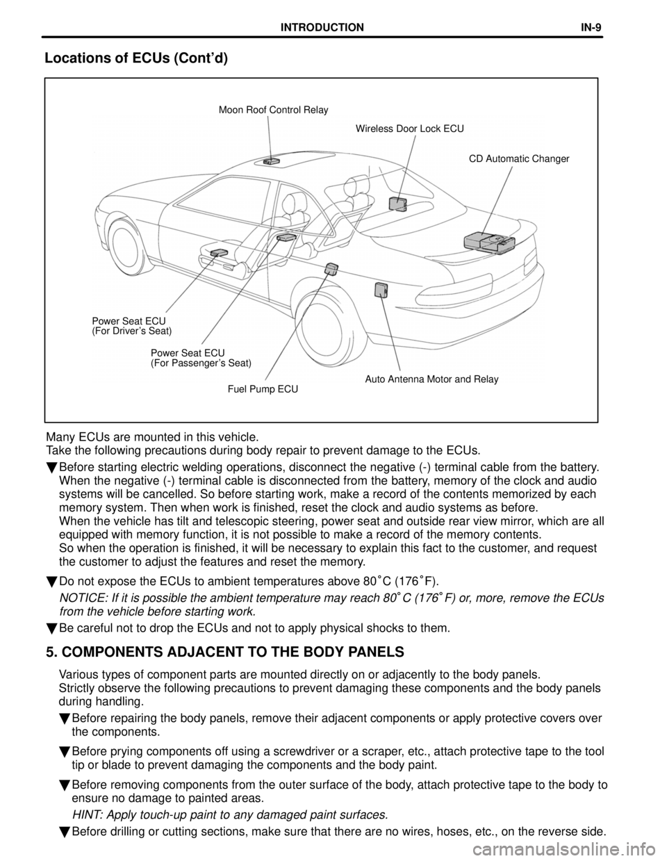
Fuel Pump ECUAuto Antenna Motor and Relay
Power Seat ECU
(For Passenger's Seat)
Power Seat ECU
(For Driver's Seat) CD Automatic Changer
Wireless Door Lock ECU
Moon Roof Control Relay
Locations of ECUs (Cont'd)
Many ECUs are mounted in this vehicle.
Take the following precautions during body repair to prevent damage to th\
e ECUs.
�
Before starting electric welding operations, disconnect the negative (-\
) terminal cable from the battery.
When the negative (-) terminal cable is disconnected from the battery, memory of the clock and audio
systems will be cancelled. So before starting work, make a record of the\
contents memorized by each
memory system. Then when work is finished, reset the clock and audio sys\
tems as before.
When the vehicle has tilt and telescopic steering, power seat and outsid\
e rear view mirror, which are all
equipped with memory function, it is not possible to make a record of th\
e memory contents.
So when the operation is finished, it will be necessary to explain this \
fact to the customer, and request
the customer to adjust the features and reset the memory.
� Do not expose the ECUs to ambient temperatures above 80 °C (176 °F).
NOTICE: If it is possible the ambient temperature may reach 80°C (176°F) or, more, remove the ECUs
from the vehicle before starting work.
� Be careful not to drop the ECUs and not to apply physical shocks to them\
.
5. COMPONENTS ADJACENT TO THE BODY PANELS
Various types of component parts are mounted directly on or adjacently to\
the body panels.
Strictly observe the following precautions to prevent damaging these com\
ponents and the body panels
during handling.
�Before repairing the body panels, remove their adjacent components or ap\
ply protective covers over
the components.
� Before prying components off using a screwdriver or a scraper, etc., attach protective tape to the tool
tip or blade to prevent damaging the components and the body paint.
� Before removing components from the outer surface of the body, attach protective tape to the body to
ensure no damage to painted areas.
HINT: Apply touch-up paint to any damaged paint surfaces.
�Before drilling or cutting sections, make sure that there are no wires, \
hoses, etc., on the reverse side.
INTRODUCTIONIN-9
WhereEverybodyKnowsYourName
Page 1289 of 4087
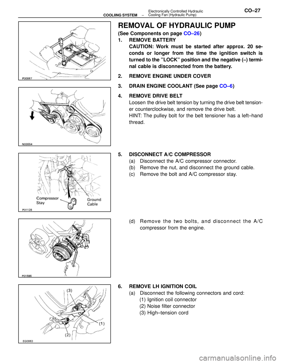
REMOVAL OF HYDRAULIC PUMP
(See Components on page CO±26)
1. REMOVE BATTERY CAUTION: Work must be started after approx. 20 se-
conds or longer from the time the ignition switch is
turned to the ºLOCKº position and the negative (±) termi-
nal cable is disconnected from the battery.
2. REMOVE ENGINE UNDER COVER
3. DRAIN ENGINE COOLANT (See page CO±6)
4. REMOVE DRIVE BELT Loosen the drive belt tension by turning the drive belt tension-
er counterclockwise, and remove the drive belt.
HINT: The pulley bolt for the belt tensioner has a left±hand
thread.
5. DISCONNECT A/C COMPRESSOR (a) Disconnect the A/C compressor connector.
(b) Remove the nut, and disconnect the ground cable.
(c) Remove the bolt and A/C compressor stay.
(d) R e m o v e t h e t w o b o l t s , a n d d i s c onnect the A/C
compressor from the engine.
6. REMOVE LH IGNITION COIL (a) Disconnect the following connectors and cord:(1) Ignition coil connector
(2) Noise filter connector
(3) High±tension cord
±
COOLIING SYSTEM Electronically Controlled Hydraulic
Cooling Fan (Hydraulic Pump)CO±27
WhereEverybodyKnowsYourName
Page 1294 of 4087
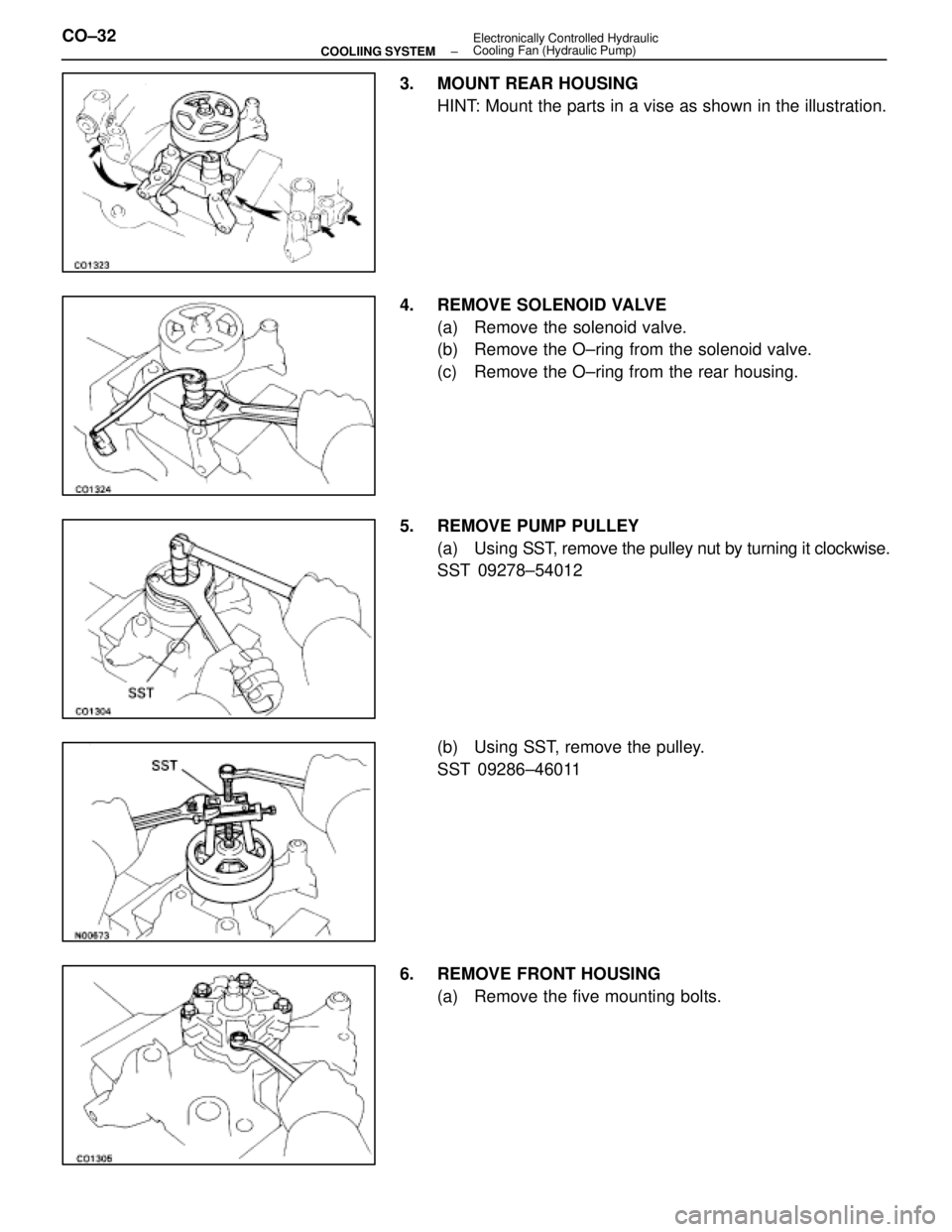
3. MOUNT REAR HOUSINGHINT: Mount the parts in a vise as shown in the illustration.
4. REMOVE SOLENOID VALVE (a) Remove the solenoid valve.
(b) Remove the O±ring from the solenoid valve.
(c) Remove the O±ring from the rear housing.
5. REMOVE PUMP PULLEY (a) Using SST, remove the pulley nut by turning it clockwise.
SST 09278±54012
(b) Using SST, remove the pulley.
SST 09286±46011
6. REMOVE FRONT HOUSING (a) Remove the five mounting bolts.
CO±32
±
COOLIING SYSTEM Electronically Controlled Hydraulic
Cooling Fan (Hydraulic Pump)
WhereEverybodyKnowsYourName
Page 1303 of 4087
(c) Using SST, install the pulley with the nut. Tighten the nut
by turning it counterclockwise.
SST 09278±54012
Torque: 59 N Vm (600 kgf Vcm, 43 ft Vlbf)
12. INSTALL SOLENOID VALVE
(a) Install a new O±ring to the solenoid valve.
(b) Install a new O±ring to the rear housing groove.
(c) Apply fluid to the two O±rings.
(d) Install the solenoid valve.
Torque: 39 N Vm (400 kgf Vcm, 28 ft Vlbf)
13. INSTALL WIRE CLAMP
(a) Install the wire clamp to the read wire.
(b) Install the wire clamp to the rear housing.
14. INSTALL SUCTION PORT UNION (a) Install the O±ring to the port union.
(b) Apply fluid to the O±ring.
(c) Install the port union with the bolt.
Torque: 13 N Vm (135 kgf Vcm, 10 ft Vlbf)
±
COOLIING SYSTEM Electronically Controlled Hydraulic Cooling Fan
(Hydraulic Pump)CO±41
WhereEverybodyKnowsYourName
Page 1307 of 4087
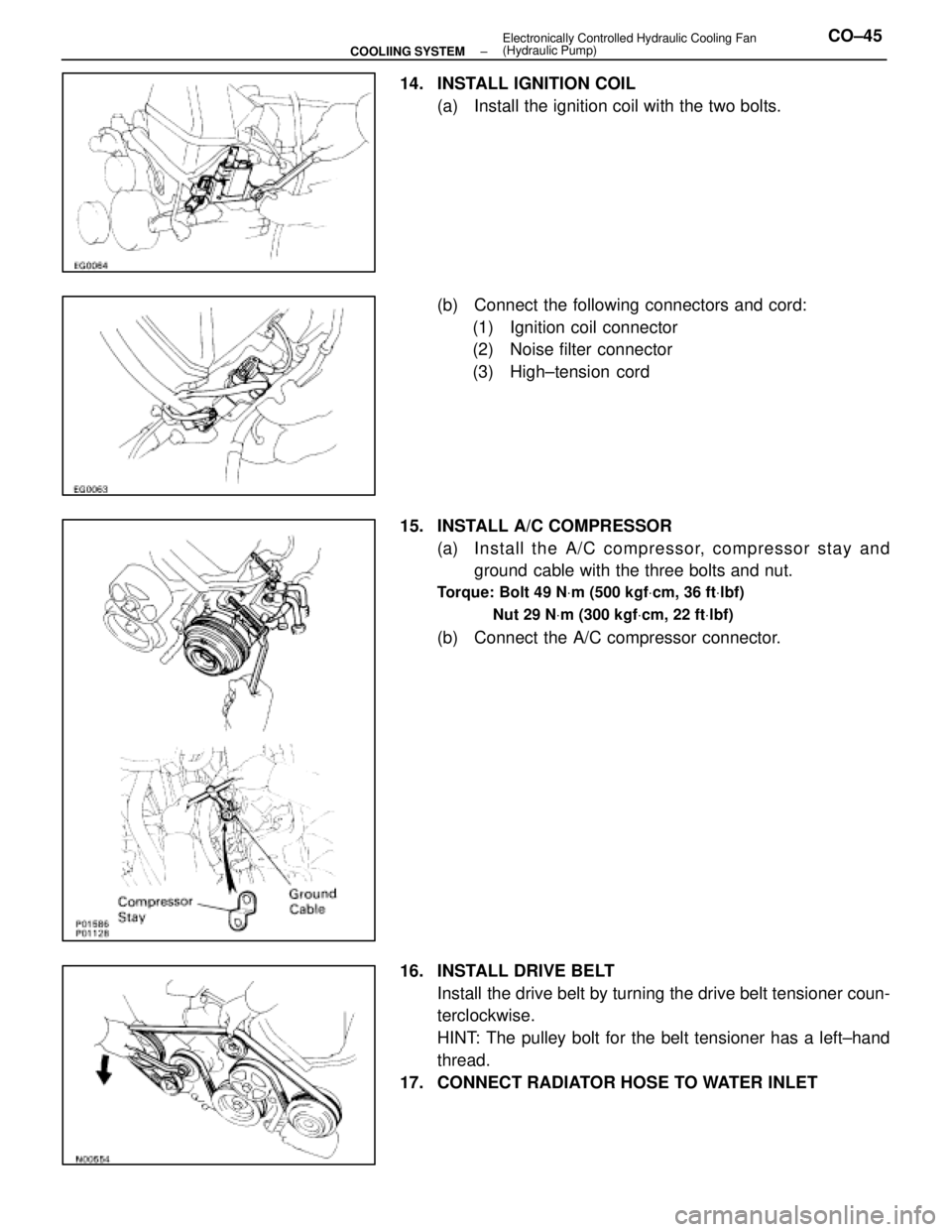
14. INSTALL IGNITION COIL(a) Install the ignition coil with the two bolts.
(b) Connect the following connectors and cord:(1) Ignition coil connector
(2) Noise filter connector
(3) High±tension cord
15. INSTALL A/C COMPRESSOR (a) In sta ll th e A/C co mp re sso r, co mp re sso r sta y an dground cable with the three bolts and nut.
Torque: Bolt 49 N Vm (500 kgf Vcm, 36 ft Vlbf)
Nut 29 N Vm (300 kgf Vcm, 22 ft Vlbf)
(b) Connect the A/C compressor connector.
16. INSTALL DRIVE BELT Install the drive belt by turning the drive belt tensioner coun-
terclockwise.
HINT: The pulley bolt for the belt tensioner has a left±hand
thread.
17. CONNECT RADIATOR HOSE TO WATER INLET
±
COOLIING SYSTEM Electronically Controlled Hydraulic Cooling Fan
(Hydraulic Pump)CO±45
WhereEverybodyKnowsYourName
Page 1312 of 4087
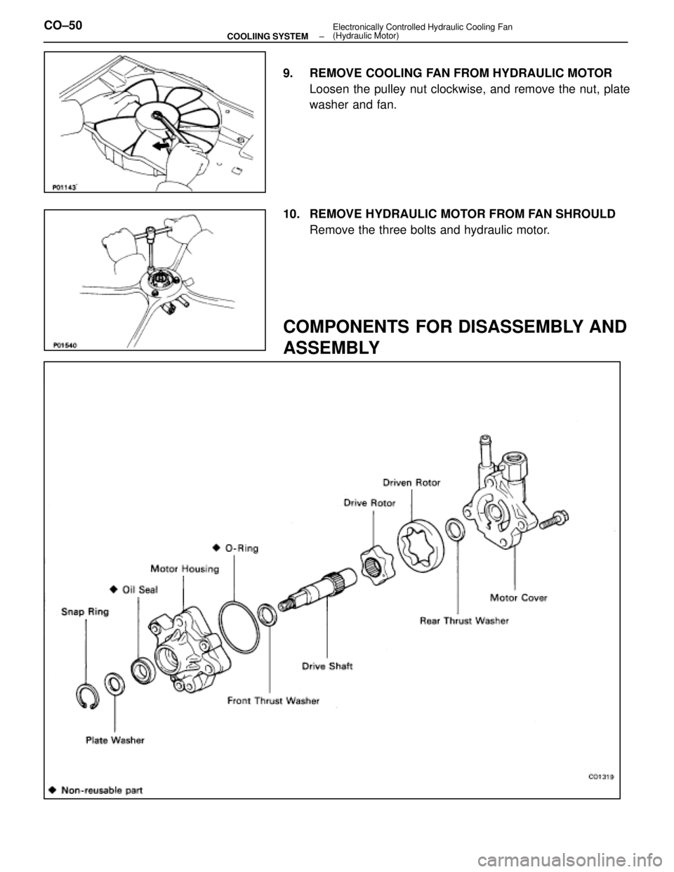
9. REMOVE COOLING FAN FROM HYDRAULIC MOTORLoosen the pulley nut clockwise, and remove the nut, plate
washer and fan.
10. REMOVE HYDRAULIC MOTOR FROM FAN SHROULD Remove the three bolts and hydraulic motor.
COMPONENTS FOR DISASSEMBLY AND
ASSEMBLY
CO±50±
COOLIING SYSTEM Electronically Controlled Hydraulic Cooling Fan
(Hydraulic Motor)
WhereEverybodyKnowsYourName
Page 1317 of 4087
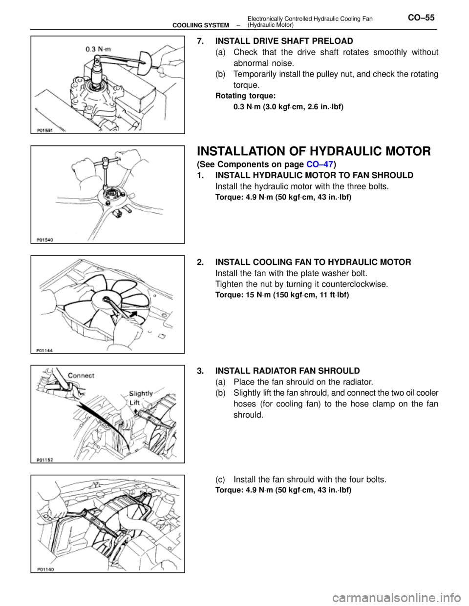
7. INSTALL DRIVE SHAFT PRELOAD(a) Check that the drive shaft rotates smoothly withoutabnormal noise.
(b) Temporarily install the pulley nut, and check the rotating
torque.
Rotating torque:
0.3 N Vm (3.0 kgf Vcm, 2.6 in. Vlbf)
INSTALLATION OF HYDRAULIC MOTOR
(See Components on page CO±47)
1. INSTALL HYDRAULIC MOTOR TO FAN SHROULD Install the hydraulic motor with the three bolts.
Torque: 4.9 N Vm (50 kgf Vcm, 43 in. Vlbf)
2. INSTALL COOLING FAN TO HYDRAULIC MOTOR
Install the fan with the plate washer bolt.
Tighten the nut by turning it counterclockwise.
Torque: 15 N Vm (150 kgf Vcm, 11 ft Vlbf)
3. INSTALL RADIATOR FAN SHROULD
(a) Place the fan shrould on the radiator.
(b) Slightly lift the fan shrould, and connect the two oil cooler
hoses (for cooling fan) to the hose clamp on the fan
shrould.
(c) Install the fan shrould with the four bolts.
Torque: 4.9 N Vm (50 kgf Vcm, 43 in. Vlbf)
±
COOLIING SYSTEM Electronically Controlled Hydraulic Cooling Fan
(Hydraulic Motor)CO±55
WhereEverybodyKnowsYourName
Page 1330 of 4087
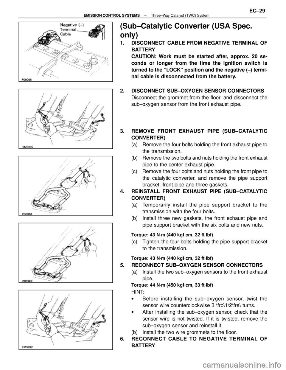
(Sub±Catalytic Converter (USA Spec.
only)
1. DISCONNECT CABLE FROM NEGATIVE TERMINAL OFBATTERY
CAUTION: Work must be started after, approx. 20 se-
conds or longer from the time the ignition switch is
turned to the ºLOCKº position and the negative (±) termi-
nal cable is disconnected from the battery.
2. DISCONNECT SUB±OXYGEN SENSOR CONNECTORS Disconnect the grommet from the floor, and disconnect the
sub±oxygen sensor from the front exhaust pipe.
3. REMOVE FRONT EXHAUST PIPE (SUB±CATALYTIC CONVERTER)
(a) Remove the four bolts holding the front exhaust pipe tothe transmission.
(b) Remove the two bolts and nuts holding the front exhaust
pipe to the center exhaust pipe.
(c) Remove the four bolts and nuts holding the front pipe to the catalytic converter, and remove the pipe support
bracket, front pipe and three gaskets.
4. REINSTALL FRONT EXHAUST PIPE (SUB±CATALYTIC CONVERTER)
(a) Temporarily install the pipe support bracket to thetransmission with the four bolts.
(b) Install three new gaskets, the front exhaust pipe and pipe support bracket with the six bolts and new nuts.
Torque: 43 N Vm (440 kgf Vcm, 32 ft Vlbf)
(c) Tighten the four bolts holding the pipe support bracket
to the transmission.
Torque: 43 N Vm (440 kgf Vcm, 32 ft Vlbf)
5. RECONNECT SUB±OXYGEN SENSOR CONNECTORS
(a) Install the two sub±oxygen sensors to the front exhaustpipe.
Torque: 44 N Vm (450 kgf Vcm, 33 ft Vlbf)
HINT:
w Before installing the s ub±oxygen sensor, twist the
sensor wire counterclockwise 3 \frb\1/2\fre turns.
w After installing the sub±oxygen sensor, check that the
sensor wire is not twisted. If it is twisted, remove the
sub±oxygen sensor and reinstall it.
(b) Install the two wire grommets to the floor.
6. RECONNECT CABLE TO NEGATIVE TERMINAL OF
BATTERY
±
EMISSION CONTROL SYSTEMS Three±Way Catalyst (TWC) SystemEC±29
WhereEverybodyKnowsYourName