Page 1584 of 4087

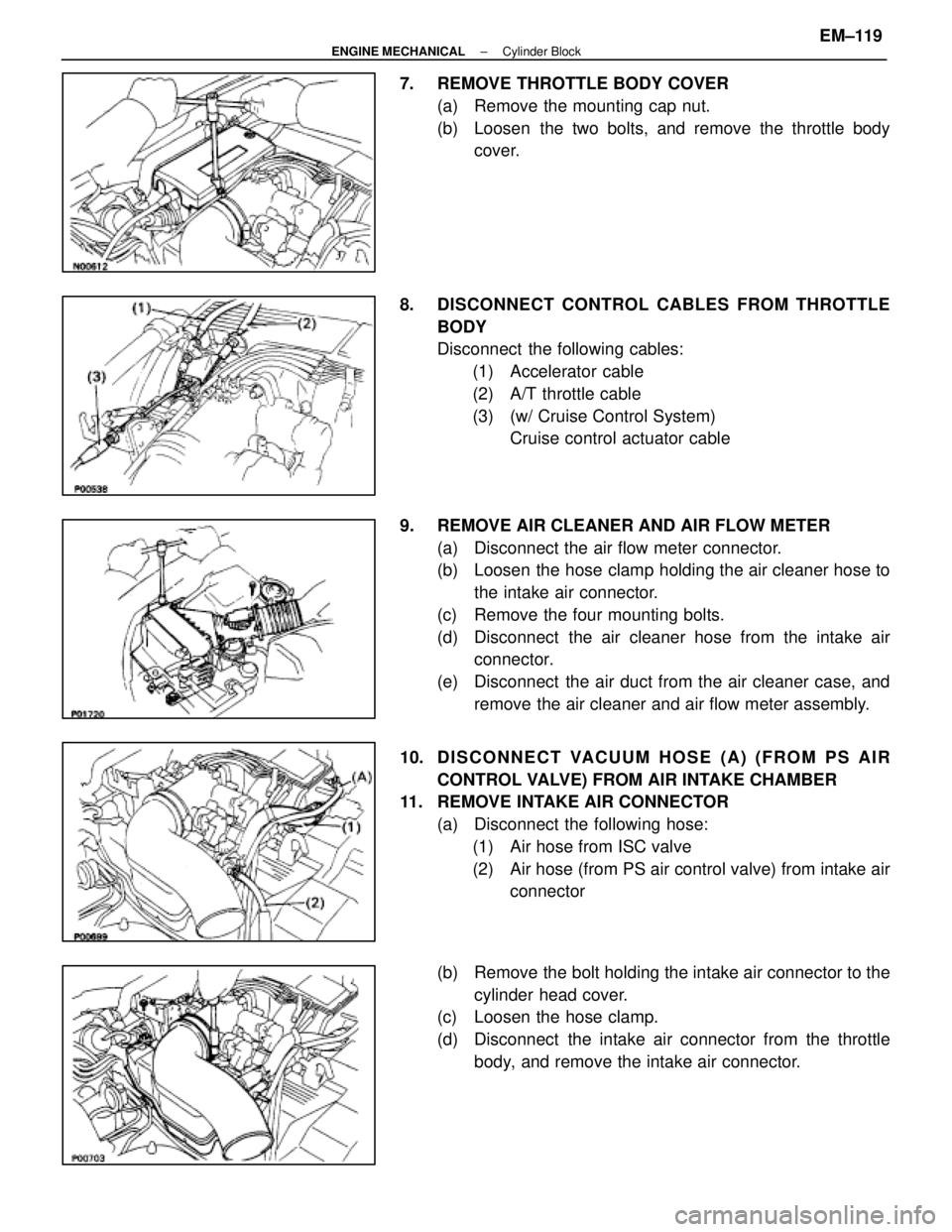
7. REMOVE THROTTLE BODY COVER(a) Remove the mounting cap nut.
(b) Loosen the two bolts, and remove the throttle bodycover.
8. DISCONNECT CONTROL CABLES FROM THROTTLE BODY
Disconnect the following cables:(1) Accelerator cable
(2) A/T throttle cable
(3) (w/ Cruise Control System) Cruise control actuator cable
9. REMOVE AIR CLEANER AND AIR FLOW METER (a) Disconnect the air flow meter connector.
(b) Loosen the hose clamp holding the air cleaner hose tothe intake air connector.
(c) Remove the four mounting bolts.
(d) Disconnect the air cleaner hose from the intake air connector.
(e) Disconnect the air duct from the air cleaner case, and remove the air cleaner and air flow meter assembly.
10. D I S C O N N E C T VA CUUM HOSE (A) (FROM PS AIR
CONTROL VALVE) FROM AIR INTAKE CHAMBER
11. REMOVE INTAKE AIR CONNECTOR
(a) Disconnect the following hose:(1) Air hose from ISC valve
(2) Air hose (from PS air control valve) from intake air connector
(b) Remove the bolt holding the intake air connector to the cylinder head cover.
(c) Loosen the hose clamp.
(d) Disconnect the intake air connector from the throttle
body, and remove the intake air connector.
±
ENGINE MECHANICAL Cylinder BlockEM±119
WhereEverybodyKnowsYourName
Page 1641 of 4087

(c) Connect the following hoses:(1) Reservoir hose to water inlet housing
(2) Reservoir hose to radiator
(d) Connect the coolant level sensor connector.
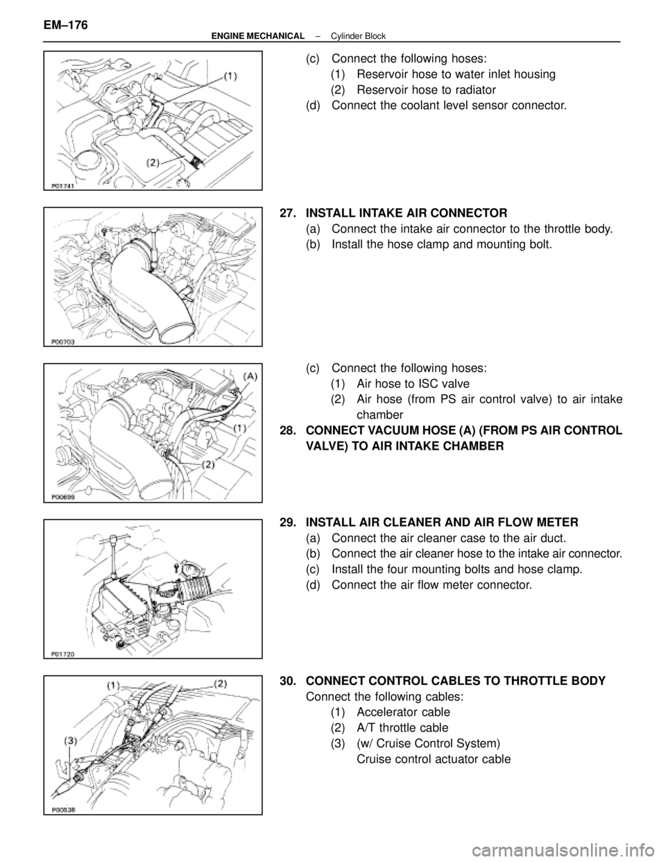
27. INSTALL INTAKE AIR CONNECTOR (a) Connect the intake air connector to the throttle body.
(b) Install the hose clamp and mounting bolt.
(c) Connect the following hoses:(1) Air hose to ISC valve
(2) Air hose (from PS air control valve) to air intake chamber
28. CONNECT VACUUM HOSE (A) (FROM PS AIR CONTROL VALVE) TO AIR INTAKE CHAMBER
29. INSTALL AIR CLEANER AND AIR FLOW METER (a) Connect the air cleaner case to the air duct.
(b) Connect the air cleaner hose to the intake air connector.
(c) Install the four mounting bolts and hose clamp.
(d) Connect the air flow meter connector.
30. CONNECT CONTROL CABLES TO THROTTLE BODY Connect the following cables:(1) Accelerator cable
(2) A/T throttle cable
(3) (w/ Cruise Control System)
Cruise control actuator cable
EM±176
±
ENGINE MECHANICAL Cylinder Block
WhereEverybodyKnowsYourName
Page 1657 of 4087
INSPECTION AND ADJUSTMENT OF
VALVE CLEARANCE
HINT: Inspect and adjust the valve clearance when the en-
gine is cold.
1. DISCONNECT CABLE FROM NEGATIVE TERMINAL OF BATTERY
CAUTION: Turn the ignition switch to ºLOCKº. Discon-
nect the cable from the negative (±) terminal of the bat-
tery. Wait at least 20 seconds before procceding with
work.
2. DISCONNECT CONTROL CABLES FROM THROTTLE BODY
Disconnect the following cables:(1) Accelerator cable
(2) (A/T) Throttle control cable
(3) Cruise control actuator cable
3. REMOVE AIR CLEANER HOSE (a) Disconnect the following hoses:(1) PS air hose from No.
4 timing belt cover
(2) PCV hose from No. 2 cylinder head cover
(b) Loosen the two hose clamps and remove the air cleaner
hose.
4. REMOVE EGR PIPE (a) Loosen the union nut.
(b) Remove the two bolts, EGR pipe and gasket.
5. REMOVE THROTTLE BODY BRACKET Remove the four nuts and throttle body bracket.
EM±10
±
ENGINE MECHANICAL Engine Tune±Up
WhereEverybodyKnowsYourName
Page 1666 of 4087
19. REINSTALL AIR CLEANER HOSE(a) Install the air cleaner hose with two hose clamps.
(b) Connect the following hoses:(1) PS air hose to No. 4 timing belt cover
(2) PCV hose to No. 2 cylinder head cover
20. RECONNECT CONTROL CABLES TO THROTTLE BODY
Connect the following hoses:
(1) Accelerator cable
(2) (A/T) Throttle control cable
(3) Cruise control actuator cable
21. RE CO NNE CT CABLE TO NE G ATIV E TE RMINAL OF BATTERY
INSPECTION OF IGNITION TIMING
(See page IG±14)
Ignition timing:
105 BTDC @ idle
(w/ Terminals TE1 and E1 connected)
INSPECTION OF IDLE SPEED
HINT: Initial conditions (See step 1 on page EM±20)
Idle speed: M/T 700
+ 50 rpm
A/T 650
+ 50 rpm (N range)
±
ENGINE MECHANICAL Engine Tune±UpEM±19
WhereEverybodyKnowsYourName
Page 1670 of 4087

INSPECTION AND ADJUSTMENT OF
VALVE CLEARANCE
HINT: Inspect and adjust the valve clearance when the
engine is cold.
1. DISCONNECT CABLE FROM NEGATIVE TERMINAL OF BATTERY
CAUTION: Work must be started after approx. 20 se-
conds or longer from the time the ignition switch is
turned to the ºLOCKº position and the negative (±) termi-
nal cable is disconnected from the battery.
2. DRAIN ENGINE COOLANT (See page CO±6)
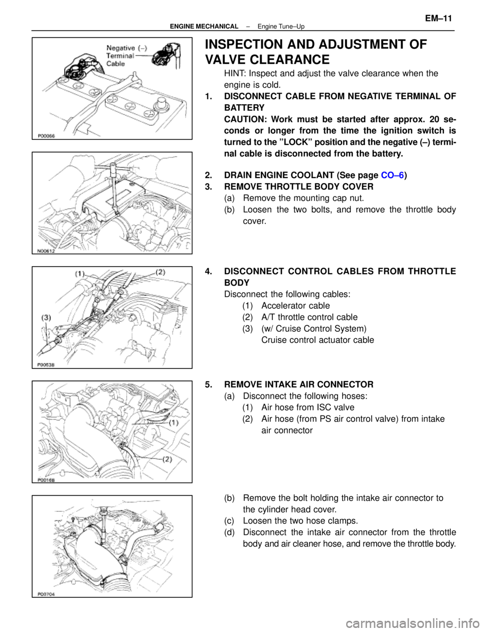
3. REMOVE THROTTLE BODY COVER (a) Remove the mounting cap nut.
(b) Loosen the two bolts, and remove the throttle body
cover.
4. DISCONNECT CONTROL CABLES FROM THROTTLE BODY
Disconnect the following cables:(1) Accelerator cable
(2) A/T throttle control cable
(3) (w/ Cruise Control System) Cruise control actuator cable
5. REMOVE INTAKE AIR CONNECTOR (a) Disconnect the following hoses:(1) Air hose from ISC valve
(2) Air hose (from PS air control valve) from intake
air connector
(b) Remove the bolt holding the intake air connector to the cylinder head cover.
(c) Loosen the two hose clamps.
(d) Disconnect the intake air connector from the throttle
body and air cleaner hose, and remove the throttle body.
±
ENGINE MECHANICAL Engine Tune±UpEM±11
WhereEverybodyKnowsYourName
Page 1686 of 4087
38. RECONNECT CONTROL CABLES TO THROTTLE BODYConnect the following hoses:(1) Accelerator cable
(2) A/T throttle control cable
(3) (w/ Cruise Control System) Cruise control actuator cable
39. REINSTALL THROTTLE BODY COVER Install the throttle body cover and hose clamp with the two
bolts and cap nut.
40. RE CO NNE CT CABLE TO NE G ATIV E TE RMINAL OF BATTERY
41. FILL WITH ENGINE COOLANT (See page CO±7)
INSPECTION OF IGNITION TIMING
(See page IG±28)
Ignition timing:
8±125 BTDC @ idle
(w/ Terminals TE1 and E1 connected)
INSPECTION OF IDLE SPEED
HINT:
w Initial conditions (See step 1 on page EM±28)
w Set the tachometer to the 4±cylinder range.
Idle speed: 700 + 50 rpm
±
ENGINE MECHANICAL Engine Tune±UpEM±27
WhereEverybodyKnowsYourName
Page 1762 of 4087
5. REMOVE THROTTLE BODY COVER(a) Remove the mounting cap nut.
(b) Loosen the two bolts, and remove the throttle bodycover.
6. DISCONNECT CONTROL CABLES FROM THROTTLE BODY
Disconnect the following cables:(1) Accelerator cable
(2) A/T throttle control cable
(3) (w/ Cruise Control System) Cruise control actuator cable
7. REMOVE RH IGNITION COIL Remove the two bolts and ignition coil.
8. REMOVE WATER INLET AND INLET HOUSING (a) Disconnect the water by±pass hose from the ISC valve.
(b) Remove the two bolts holding the water inlet housing to the water pump.
(c) Pull out the water inlet and inlet housing assembly.
(d) Remove the O±ring from the water inlet housing.
±
ENGINE MECHANICAL Cylinder HeadsEM±61
WhereEverybodyKnowsYourName
Page 1815 of 4087

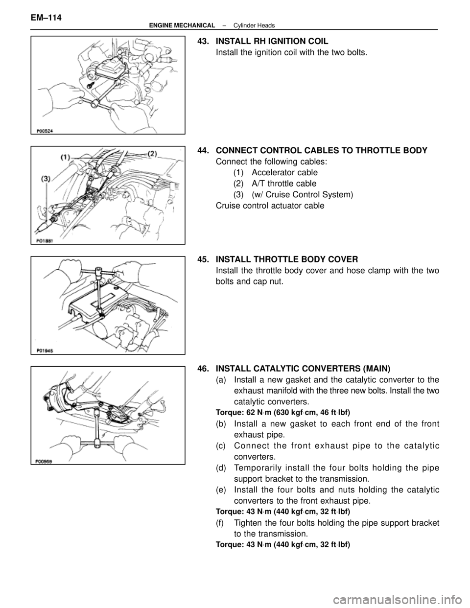
43. INSTALL RH IGNITION COILInstall the ignition coil with the two bolts.
44. CONNECT CONTROL CABLES TO THROTTLE BODY Connect the following cables:(1) Accelerator cable
(2) A/T throttle cable
(3) (w/ Cruise Control System)
Cruise control actuator cable
45. INSTALL THROTTLE BODY COVER Install the throttle body cover and hose clamp with the two
bolts and cap nut.
46. INSTALL CATALYTIC CONVERTERS (MAIN) (a) Install a new gasket and the catalytic converter to theexhaust manifold with the three new bolts. Install the two
catalytic converters.
Torque: 62 N Vm (630 kgf Vcm, 46 ft Vlbf)
(b) Install a new gasket to each front end of the front
exhaust pipe.
(c) C onnect the front exhaust pipe to the catalytic
converters.
(d) Te mp o ra rily in sta ll th e fo u r bo lts ho ld in g th e pip e support bracket to the transmission.
(e) Install the four bolts and nuts holding the catalytic
converters to the front exhaust pipe.
Torque: 43 N Vm (440 kgf Vcm, 32 ft Vlbf)
(f) Tighten the four bolts holding the pipe support bracket
to the transmission.
Torque: 43 N Vm (440 kgf Vcm, 32 ft Vlbf)
EM±114±
ENGINE MECHANICAL Cylinder Heads
WhereEverybodyKnowsYourName