Page 110 of 4087
 Remove console upper panel.(See pageBO-111 ).
(2) Remove A/C control assembly with connec±
tors still")
Check voltage between terminals IG+ and E of air conditioner control
assembly connector.
(1) Remove console upper panel.(See pageBO-111 ).
(2) Remove A/C control assembly with connec±
tors still connected.
(3) Turn ignition switch ON.
Measure voltage between terminals IG+ and E of air
conditioner control assembly.
Voltage: 10 ±14 V
Proceed to next circuit inspection shown on matrix
chart (See page AC-36).
Check continuity between terminals E of air conditioner control assem-
bly and body ground.
Measure resistance between terminals E of air condi-
tioner control assembly and body ground.
Resistance:�1 �� or less
Repair or replace harness or connector.
Remove HTR fuse from J/B No. 1.
Check continuity of HTR fuse
Continuity
Check HTR fuse.
Check for short in all the harness and
components connected to the HTR fuse
See attached wiring diagram).
Check and repair harness and connector between air conditioner control \
assembly and battery.
INSPECTION PROCEDURE
±
AIR CONDITIONING SYSTEM TroubleshootingAC±71
WhereEverybodyKnowsYourName
Page 111 of 4087
ACC Power Source Circuit
CIRCUIT DESCRIPTION
This circuit supplies power to the air conditioner control assembly (contai\
ns the A/C control assembly).
DIAGNOSTIC CHART
WIRING DIAGRAM
Check voltage between terminals ACC of air
conditioner control assembly connector
and body ground.
Check RADIO No. 2 fuse.
Check and repair harness and connector
between air conditioner control assembly
and battery.
Proceed to next circuit inspection
shown on matrix chart (See page
AC-36).
Check for short in all the harness
and components connected to
the RADIO No. 2 fuse (See
attached wiring diagram).
AC±72±
AIR CONDITIONING SYSTEM Troubleshooting
WhereEverybodyKnowsYourName
Page 112 of 4087
Check voltage between terminals ACC of air conditioner control
assembly connector and body ground.
(1) Remove console upper panel.(See page BO-111 ).
(2) Remove A/C control assembly with connec±
tors still connected.
(3) Turn ignition switch ON.
Measure voltage between terminals ACC of air
conditioner control assembly connector and body
ground.
Voltage: 10 ± 14 V
Proceed to next circuit inspection shown on matrix
chart (See page AC-36).
Check RADIO No. 2 fuse.
Remove RADIO No. 2 fuse from J/B No. 1.
Check continuity of RADIO No. 2 fuse.
Continuity.
Check for short in all the harness and
components connected to the RADIO No. 2
fuse (See attached wiring diagram).
Check and repair harness and connector between air conditioner control \
assembly and battery.
INSPECTION PROCEDURE
±
AIR CONDITIONING SYSTEM TroubleshootingAC±73
WhereEverybodyKnowsYourName
Page 113 of 4087
������������������\
������������������\
�
������������������\
�����������������
������������������\
������������������\
Back±up Power Source Circuit
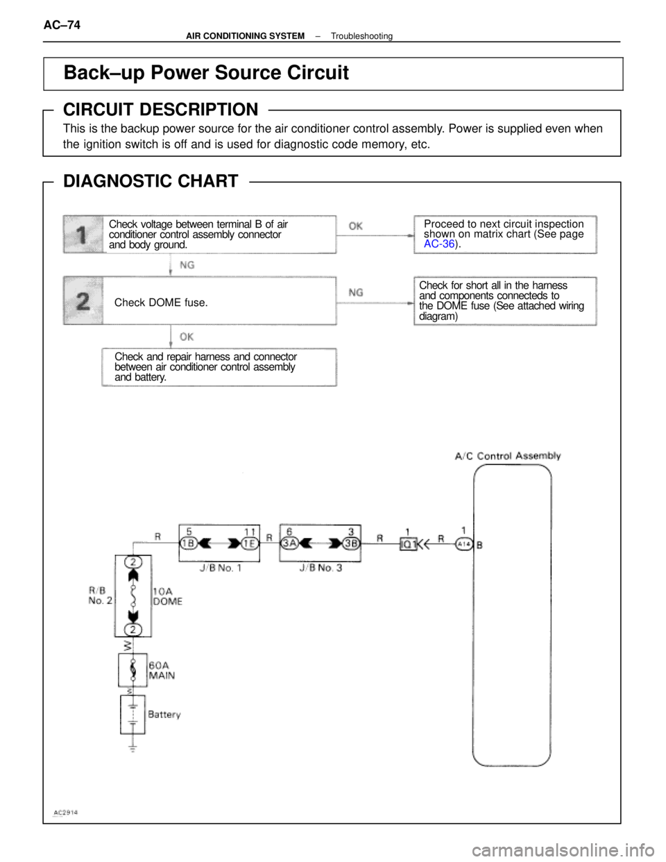
CIRCUIT DESCRIPTION
This is the backup power source for the air conditioner control assembly. Power is supplied even when
the ignition switch is off and is used for diagnostic code memory, etc.
DIAGNOSTIC CHART
WIRING DIAGRAM
Check voltage between terminal B of air
conditioner control assembly connector
and body ground.
Check DOME fuse.
Proceed to next circuit inspection
shown on matrix chart (See page
AC-36
).
Check and repair harness and connector
between air conditioner control assembly
and battery.
Check for short all in the harness
and components connecteds to
the DOME fuse (See attached wiring
diagram)
AC±74±
AIR CONDITIONING SYSTEM Troubleshooting
WhereEverybodyKnowsYourName
Page 114 of 4087
Check voltage between terminals B of air conditioner control assembly
connector and body ground.
(1) Remove console upper panel.(See page BO-111 ).
(2) Remove A/C control assembly with connec±
tors still connected.
Measure voltage between terminals B of air condi-
tioner control assembly connector and body
ground.
Voltage: 10 ± 14 V
Proceed to next circuit inspection shown on matrix
chart (See page AC-36).
Check DOME fuse.
Remove DOME fuse from R/B No. 2.
Check continuity of DOME fuse.
Continuity.
Check for short in all the harness and
components connected to the DOME fuse
(See attached wiring diagram).
Check and repair harness and connector between air conditioner control \
assembly and battery.
INSPECTION PROCEDURE
±
AIR CONDITIONING SYSTEM TroubleshootingAC±75
WhereEverybodyKnowsYourName
Page 115 of 4087
������������������\
������������������\
�
������������������\
�����������������
������������������\
������������������\
Heater Main Relay Circuit
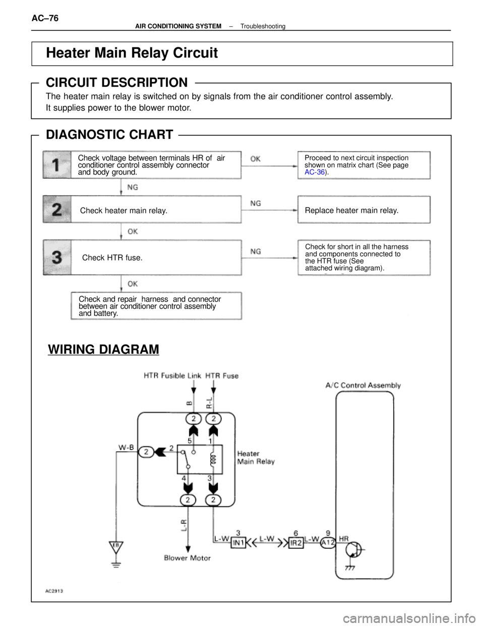
CIRCUIT DESCRIPTION
The heater main relay is switched on by signals from the air conditioner co\
ntrol assembly.
It supplies power to the blower motor.
DIAGNOSTIC CHART
Check voltage between terminals HR of air
conditioner control assembly connector
and body ground.
Check heater main relay.
Check HTR fuse.
Check and repair harness and connector
between air conditioner control assembly
and battery.
Proceed to next circuit inspection
shown on matrix chart (See page
AC-36
).
Check for short in all the harness
and components connected to
the HTR fuse (See
attached wiring diagram).
Replace heater main relay.
WIRING DIAGRAM
AC±76±
AIR CONDITIONING SYSTEM Troubleshooting
WhereEverybodyKnowsYourName
Page 116 of 4087
 Remove console upper panel.(See page BO-111 ).
(2) Remove A/C control assembly with connec±")
Check voltage between terminals HR of air conditioner control assem-
bly connector and body ground.
(1) Remove console upper panel.(See page BO-111 ).
(2) Remove A/C control assembly with connec±
tors still connected.
Proceed to next circuit inspection shown on ma-
trix chart (See page AC-36).
Check heater main relay.
Check continuity between each pair of terminals of
heater main relay shown below.
Measure voltage between terminals HR of air condi-
tioner control assembly and body ground when
ignition switch is on and off.
(1) Apply battery voltage between terminals 1
and 3
(2) Check continuity between each pair of ter±minal shown below.
Replace heater main relay.
Remove HTR fuse from J/B No. 1.
Check continuity of HTR fuse
Continuity
Check for short in all the harness and
components connected to the HTR fuse
See attached wiring diagram).
Check and repair harness and connector between air conditioner control \
assembly and battery.
INSPECTION PROCEDURE
±
AIR CONDITIONING SYSTEM TroubleshootingAC±77
WhereEverybodyKnowsYourName
Page 117 of 4087
������������������\
������������������\
�
������������������\
�����������������
������������������\
������������������\
Power Transistor Circuit
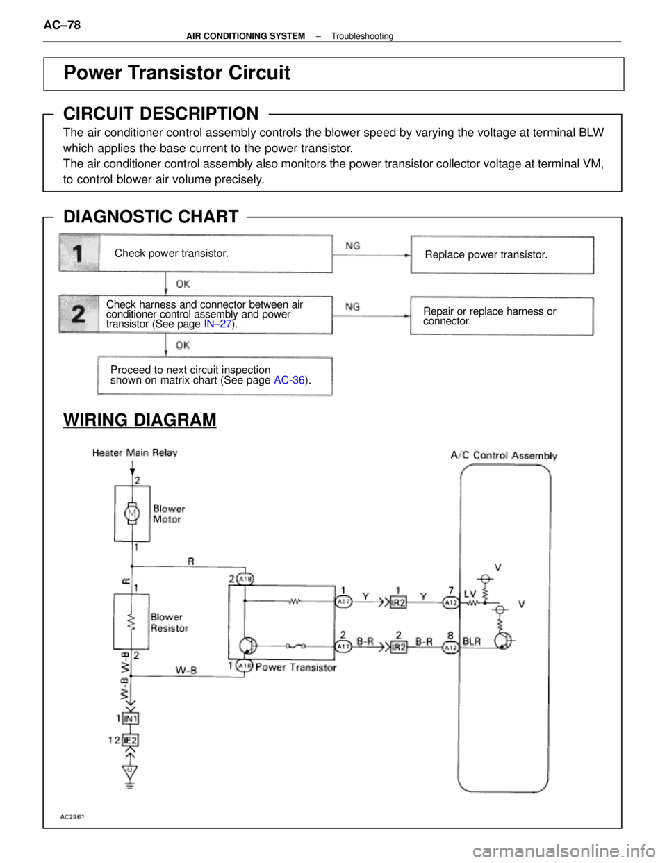
CIRCUIT DESCRIPTION
The air conditioner control assembly controls the blower speed by varying the vo\
ltage at terminal BLW
which applies the base current to the power transistor.
The air conditioner control assembly also monitors the power transistor col\
lector voltage at terminal VM,
to control blower air volume precisely.
DIAGNOSTIC CHART
WIRING DIAGRAM
Check power transistor.
Check harness and connector between air
conditioner control assembly and power
transistor (See page
IN±27).
Proceed to next circuit inspection
shown on matrix chart (See page AC-36).
Replace power transistor.
Repair or replace harness or
connector.
AC±78±
AIR CONDITIONING SYSTEM Troubleshooting
WhereEverybodyKnowsYourName
.
DIAGNOSTIC CHART
WIRING DIAGRAM
Check voltage b")
 Remove console upper panel.(See page BO-111 ).
(2) Remove A/C control assembly with connec±
t")
 Remove console upper panel.(See page BO-111 ).
(2) Remove A/C control assembly with connec±
tors")