1991 FORD FESTIVA coolant temperature
[x] Cancel search: coolant temperaturePage 220 of 454
BRAKES
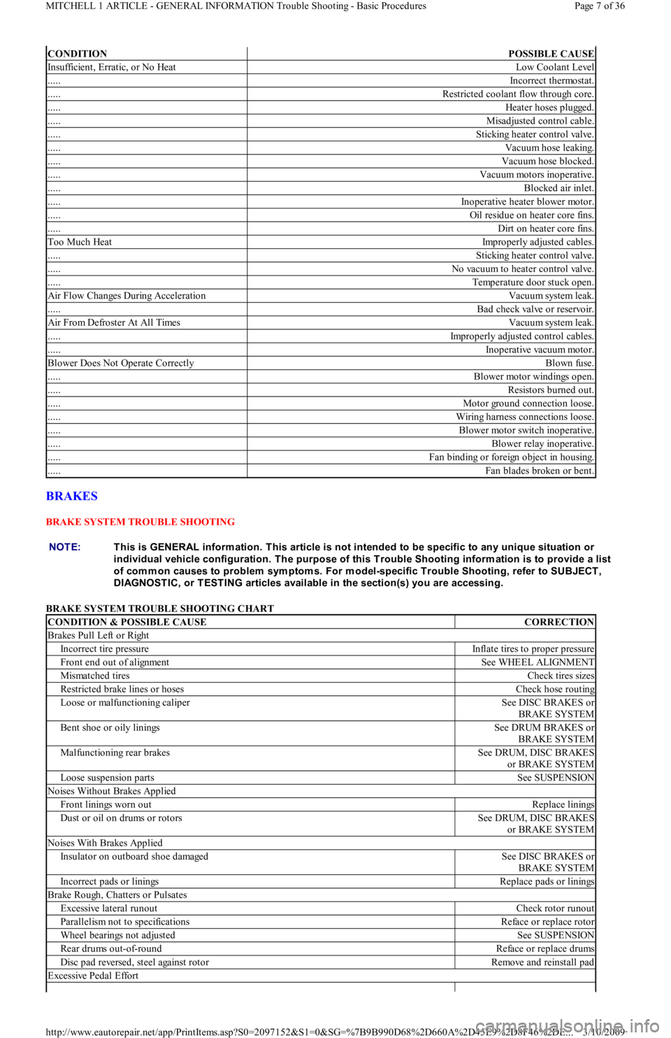
BRAKE SYSTEM TROUBLE SHOOTING
BRAKE SYSTEM TROUBLE SHOOTING CHART
CONDITIONPOSSIBLE CAUSE
Insufficient, Erratic, or No HeatLow Coolant Level
.....Incorrect thermostat.
.....Restricted coolant flow through core.
.....Heater hoses plugged.
.....Misadjusted control cable.
.....Sticking heater control valve.
.....Vacuum hose leaking.
.....Vacuum hose blocked.
.....Vacuum motors inoperative.
.....Blocked air inlet.
.....Inoperative heater blower motor.
.....Oil residue on heater core fins.
.....Dirt on heater core fins.
Too Much HeatImproperly adjusted cables.
.....Sticking heater control valve.
.....No vacuum to heater control valve.
.....Temperature door stuck open.
Air Flow Changes During AccelerationVacuum system leak.
.....Bad check valve or reservoir.
Air From Defroster At All TimesVacuum system leak.
.....Improperly adjusted control cables.
.....Inoperative vacuum motor.
Blower Does Not Operate CorrectlyBlown fuse.
.....Blower motor windings open.
.....Resistors burned out.
.....Motor ground connection loose.
.....Wiring harness connections loose.
.....Blower motor switch inoperative.
.....Blower relay inoperative.
.....Fan binding or foreign object in housing.
.....Fan blades broken or bent.
NOTE:This is GENERAL inform ation. This article is not intended to be specific to any unique situation or
individual vehicle configuration. T he purpose of this T rouble Shooting inform ation is to provide a list
of com m on causes to problem sym ptom s. For m odel-specific T rouble Shooting, refer to SUBJECT ,
DIAGNOST IC, or T EST ING articles available in the section(s) you are accessing.
CONDITION & POSSIBLE CAUSECORRECTION
Brakes Pull Left or Right
Incorrect tire pressureInflate tires to proper pressure
Front end out of alignmentSee WHEEL ALIGNMENT
Mismatched tiresCheck tires sizes
Restricted brake lines or hosesCheck hose routing
Loose or malfunctioning caliperSee DISC BRAKES or
BRAKE SYSTEM
Bent shoe or oily liningsSee DRUM BRAKES or
BRAKE SYSTEM
Malfunctioning rear brakesSee DRUM, DISC BRAKES
or BRAKE SYSTEM
Loose suspension partsSee SUSPENSION
Noises Without Brakes Applied
Front linings worn outReplace linings
Dust or oil on drums or rotorsSee DRUM, DISC BRAKES
or BRAKE SYSTEM
Noises With Brakes Applied
Insulator on outboard shoe damagedSee DISC BRAKES or
BRAKE SYSTEM
Incorrect pads or liningsReplace pads or linings
Brake Rough, Chatters or Pulsates
Excessive lateral runoutCheck rotor runout
Parallelism not to specificationsReface or replace rotor
Wheel bearings not adjustedSee SUSPENSION
Rear drums out-of-roundReface or replace drums
Disc pad reversed, steel against rotorRemove and reinstall pad
Excessive Pedal Effort
Page 7 of 36 MITCHELL 1 ARTICLE - GENERAL INFORMATION Trouble Shooting - Basic Procedures
3/10/2009 http://www.eautorepair.net/app/PrintItems.asp?S0=2097152&S1=0&SG=%7B9B990D68%2D660A%2D45E9%2D8F46%2DE
...
Page 230 of 454

IGNITION SYSTEM TROUBLE SHOOTING
Open coolant temperature sensor circuitTest sensor and wiring
Shorted W.O.T. switch in T.P.S.Disconnect W.O.T. switch,
engine should start
Defective ECMReplace ECM
Fuel tank residual pressure valve leaksTest for fuel pressure drop
after shut down
Hard Starting
Disconnected hot air tube to air cleanerReconnect tube and test
control valve
Defective Idle Air Control (IAC) valveTest valve operation and
circuit
Shorted, open or misadjusted T.P.S.Test and adjust or replace
T.P.S.
EGR valve openTest EGR valve and control
circuit
Poor Oxygen sensor signalTest for shorted or circuit
Incorrect mixture from PCV systemTest PCV for flow, check
sealing of oil filter cap
Poor High Speed Operation
Low fuel pump volumeFaulty pump or restricted fuel
lines or filters
Poor MAP sensor signalTest MAP sensor, vacuum
hose and wiring
Poor Oxygen sensor signalTest for shorted or open
sensor or circuit
Open coolant temperature sensor circuitTest sensor and wiring
Faulty ignition operationCheck wires for cracks or poor
con- nections, test secondary
voltage with oscilloscope
Contaminated fuelTest fuel for water or alcohol
Intermittent ECM groundTest ECM ground connection
for resistance
Restricted air cleanerReplace air cleaner
Restricted exhaust systemTest for exhaust manifold back
pressure
Poor MAF sensor signalCheck leakage between sensor
and manifold
Poor VSS signalIf tester for ALCL hook-up is
available check that VSS
reading matches speedometer
Ping or Knock on Acceleration
Poor Knock sensor signalTest for shorted or open
sensor or circuit
Poor Baro sensor signalTest for shorted or open
sensor or circuit
Improper ignition timingSee VEHICLE EMISSION
CONTROL LABEL (where
applicable)
Check for engine overheating problemsLow coolant, loose belts or
electric cooling fan inoperative
NOTE:For additional electronic fuel injection trouble shooting inform ation, see the appropriate article in the
ENGINE PERFORMANCE section (not all vehicles have Com puter Engine Control articles). Inform ation
is provided there for diagnosing fuel system problem s on vehicles with electronic fuel injection.
NOTE:This is GENERAL inform ation. This article is not intended to be specific to any unique situation or
individual vehicle configuration. T he purpose of this T rouble Shooting inform ation is to provide a list
of com m on causes to problem sym ptom s. For m odel-specific T rouble Shooting, refer to SUBJECT ,
DIAGNOST IC, or T EST ING articles available in the section(s) you are accessing.
Page 17 of 36 MITCHELL 1 ARTICLE - GENERAL INFORMATION Trouble Shooting - Basic Procedures
3/10/2009 http://www.eautorepair.net/app/PrintItems.asp?S0=2097152&S1=0&SG=%7B9B990D68%2D660A%2D45E9%2D8F46%2DE
...
Page 268 of 454

Fig. 14: Typical Negative Backpressure EGR Valve
Courtesy of GENERAL MOTORS CORP.
Digital EGR Valve
The digital EGR valve operates independently of engine manifold vacuum. This valve controls EGR flow through 3 orifices. These 3 orifices
are opened and closed by electric solenoids. The solenoids are, in turn, controlled by the Electronic Control Module (ECM). When a
solenoid is energized, the armature with attached shaft and swivel pintle is lifted, opening the orifice. See Fig. 15
.
The ECM uses inputs from the Coolant Temperature Sensor (CTS), Throttle Position Sensor (TPS) and Mass Airflow (MAF) sensors to
control the EGR orifices to make 7 different combinations for precise EGR flow control. At idle, the EGR valve allows a very small amount of
exhaust gas to enter the intake manifold. This EGR valve normally operates above idle speed during warm engine operation.
Verify EGR valve is present and not modified or purposely damaged. Ensure thermal vacuum switches, pressure transducers, speed switches,
etc., (if applicable) are not by-passed or modified. Ensure vacuum hose(s) to EGR valve is not plugged. Ensure electrical connector to EGR
valve is not disconnected.
Page 8 of 12 MITCHELL 1 ARTICLE - EMISSION CONTROL VISUAL INSPECTION PROCEDURES 1983-93 GENERAL INFORMATI
...
3/10/2009 http://www.eautorepair.net/app/PrintItems.asp?S0=2097152&S1=0&SG=%7B9B990D68%2D660A%2D45E9%2D8F46%2DE
...
Page 345 of 454
Back To Article
HEAT ER SYST EM
1990-92 HEAT ER SYST EMS Ford Motor Co.
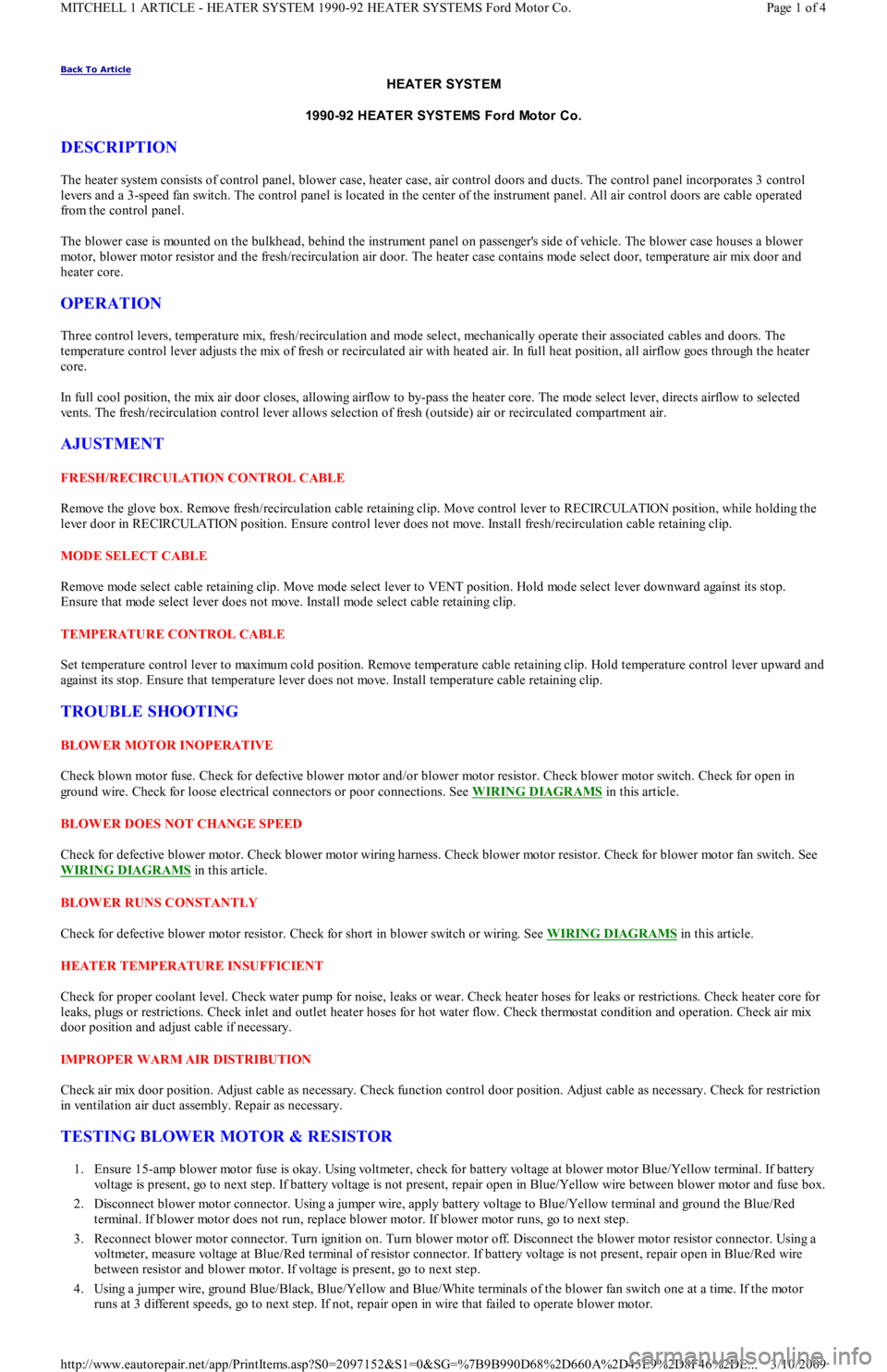
DESCRIPTION
The heater system consists of control panel, blower case, heater case, air control doors and ducts. The control panel incorporates 3 control
levers and a 3-speed fan switch. The control panel is located in the center of the instrument panel. All air control doors are cable operated
from the control panel.
The blower case is mounted on the bulkhead, behind the instrument panel on passenger's side of vehicle. The blower case houses a blower
motor, blower motor resistor and the fresh/recirculation air door. The heater case contains mode select door, temperature air mix door and
heater core.
OPERATION
Three control levers, temperature mix, fresh/recirculation and mode select, mechanically operate their associated cables and doors. The
temperature control lever adjusts the mix of fresh or recirculated air with heated air. In full heat position, all airflow goes through the heater
core.
In full cool position, the mix air door closes, allowing airflow to by-pass the heater core. The mode select lever, directs airflow to selected
vents. The fresh/recirculation control lever allows selection of fresh (outside) air or recirculated compartment air.
AJUSTMENT
FRESH/RECIRCULATION CONTROL CABLE
Remove the glove box. Remove fresh/recirculation cable retaining clip. Move control lever to RECIRCULATION position, while holding the
lever door in RECIRCULATION position. Ensure control lever does not move. Install fresh/recirculation cable retaining clip.
MODE SELECT CABLE
Remove mode select cable retaining clip. Move mode select lever to VENT position. Hold mode select lever downward against its stop.
Ensure that mode select lever does not move. Install mode select cable retaining clip.
TEMPERATURE CONTROL CABLE
Set temperature control lever to maximum cold position. Remove temperature cable retaining clip. Hold temperature control lever upward and
against its stop. Ensure that temperature lever does not move. Install temperature cable retaining clip.
TROUBLE SHOOTING
BLOWER MOTOR INOPERATIVE
Check blown motor fuse. Check for defective blower motor and/or blower motor resistor. Check blower motor switch. Check for open in
ground wire. Check for loose electrical connectors or poor connections. See WIRING DIAGRAMS
in this article.
BLOWER DOES NOT CHANGE SPEED
Check for defective blower motor. Check blower motor wiring harness. Check blower motor resistor. Check for blower motor fan switch. See
WIRING DIAGRAMS
in this article.
BLOWER RUNS CONSTANTLY
Check for defective blower motor resistor. Check for short in blower switch or wiring. See WIRING DIAGRAMS
in this article.
HEATER TEMPERATURE INSUFFICIENT
Check for proper coolant level. Check water pump for noise, leaks or wear. Check heater hoses for leaks or restrictions. Check heater core for
leaks, plugs or restrictions. Check inlet and outlet heater hoses for hot water flow. Check thermostat condition and operation. Check air mix
door position and adjust cable if necessary.
IMPROPER WARM AIR DISTRIBUTION
Check air mix door position. Adjust cable as necessary. Check function control door position. Adjust cable as necessary. Check for restriction
in ventilation air duct assembly. Repair as necessary.
TESTING BLOWER MOTOR & RESISTOR
1. Ensure 15-amp blower motor fuse is okay. Using voltmeter, check for battery voltage at blower motor Blue/Yellow terminal. If battery
voltage is present, go to next step. If battery voltage is not present, repair open in Blue/Yellow wire between blower motor and fuse box.
2. Disconnect blower motor connector. Using a jumper wire, apply battery voltage to Blue/Yellow terminal and ground the Blue/Red
terminal. If blower motor does not run, replace blower motor. If blower motor runs, go to next step.
3. Reconnect blower motor connector. Turn ignition on. Turn blower motor off. Disconnect the blower motor resistor connector. Using a
voltmeter, measure voltage at Blue/Red terminal of resistor connector. If battery voltage is not present, repair open in Blue/Red wire
between resistor and blower motor. If voltage is present, go to next step.
4. Using a jumper wire, ground Blue/Black, Blue/Yellow and Blue/White terminals of the blower fan switch one at a time. If the motor
runs at 3 different speeds, go to next step. If not, repair open in wire that failed to operate blower motor.
Page 1 of 4 MITCHELL 1 ARTICLE - HEATER SYSTEM 1990-92 HEATER SYSTEMS Ford Motor Co.
3/10/2009 http://www.eautorepair.net/app/PrintItems.asp?S0=2097152&S1=0&SG=%7B9B990D68%2D660A%2D45E9%2D8F46%2DE
...
Page 349 of 454
Back To Article
1991 AIR CONDIT IONING & HEAT
MANUAL A/C
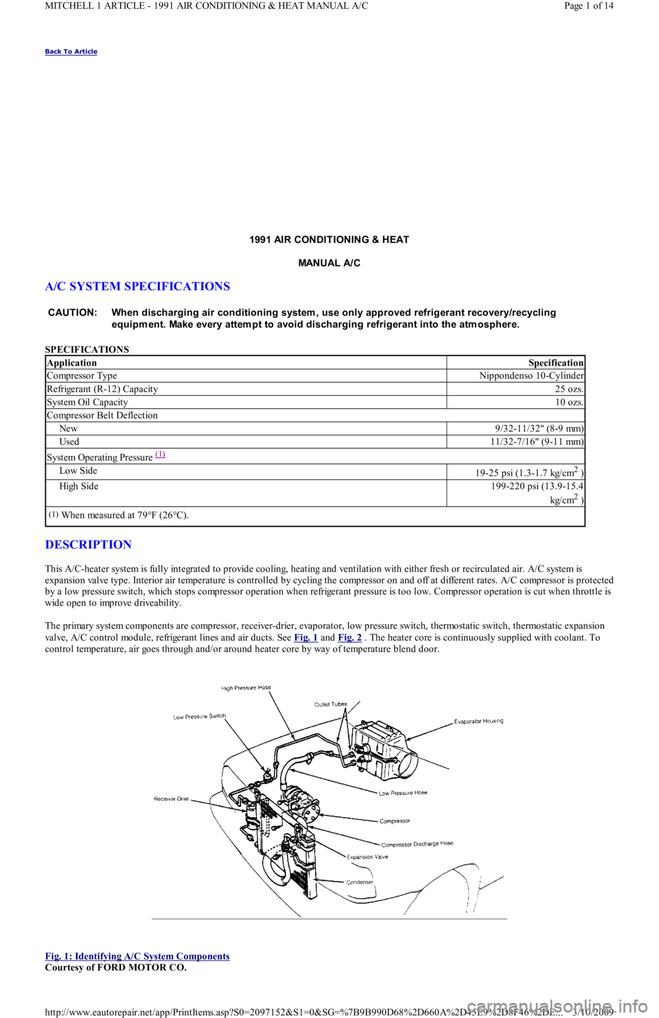
A/C SYSTEM SPECIFICATIONS
SPECIFICATIONS
DESCRIPTION
This A/C-heater system is fully integrated to provide cooling, heating and ventilation with either fresh or recirculated air. A/C system is
expansion valve type. Interior air temperature is controlled by cycling the compressor on and off at different rates. A/C compressor is protected
by a low pressure switch, which stops compressor operation when refrigerant pressure is too low. Compressor operation is cut when throttle is
wide open to improve driveability.
The primary system components are compressor, receiver-drier, evaporator, low pressure switch, thermostatic switch, thermostatic expansion
valve, A/C control module, refrigerant lines and air ducts. See Fig. 1
and Fig. 2 . The heater core is continuously supplied with coolant. To
control temperature, air goes through and/or around heater core by way of temperature blend door.
Fig. 1: Identifying A/C System Components
Courtesy of FORD MOTOR CO. CAUT ION: When discharging air conditioning system , use only approved refrigerant recovery/recycling
equipm ent. Make every attem pt to avoid discharging refrigerant into the atm osphere.
ApplicationSpecification
Compressor TypeNippondenso 10-Cylinder
Refrigerant (R-12) Capacity25 ozs.
System Oil Capacity10 ozs.
Compressor Belt Deflection
New9/32-11/32" (8-9 mm)
Used11/32-7/16" (9-11 mm)
System Operating Pressure (1)
Low Side19-25 psi (1.3-1.7 kg/cm2 )
High Side199-220 psi (13.9-15.4
kg/cm
2 )
(1)When measured at 79°F (26°C).
Page 1 of 14 MITCHELL 1 ARTICLE - 1991 AIR CONDITIONING & HEAT MANUAL A/C
3/10/2009 http://www.eautorepair.net/app/PrintItems.asp?S0=2097152&S1=0&SG=%7B9B990D68%2D660A%2D45E9%2D8F46%2DE
...
Page 374 of 454
Back To Article
SERVICE INDICATOR & WARNING LIGHTS
1988-92 MAINT ENANCE Ford Motor Co. Service Indicator & Warning Lights
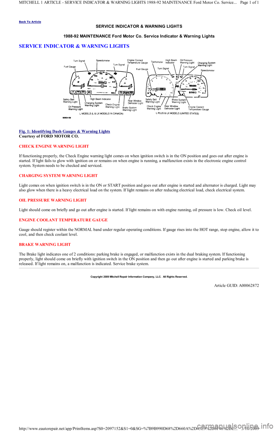
SERVICE INDICATOR & WARNING LIGHTS
Fig. 1: Identifying Dash Gauges & W arning Lights
Courtesy of FORD MOTOR CO.
CHECK ENGINE WARNING LIGHT
If functioning properly, the Check Engine warning light comes on when ignition switch is in the ON position and goes out after engine is
started. If light fails to glow with ignition on or remains on when engine is running, a malfunction exists in the electronic engine control
system. System needs to be checked and serviced.
CHARGING SYSTEM WARNING LIGHT
Light comes on when ignition switch is in the ON or START position and goes out after engine is started and alternator is charged. Light may
also glow when there is a heavy electrical load on the system. If light remains on after reducing electrical load, check electrical system.
OIL PRESSURE WARNING LIGHT
Light should come on briefly and go out after engine is started. If light remains on with engine running, oil pressure is low. Check oil level.
ENGINE COOLANT TEMPERATURE GAUGE
Gauge should register within the NORMAL band under regular operating conditions. If gauge rises into the HOT range, stop engine, allow it to
cool, and then check coolant level.
BRAKE WARNING LIGHT
The Brake light indicates one of 2 conditions: parking brake is engaged, or malfunction exists in the dual braking system. If functioning
properly, light should come on briefly with ignition switch in the ON position and then go out after engine is started and parking brake is
released. If light remains on, a malfunction is indicated. Service brake system.
Copyr ight 2009 Mitchell Repair Information Company, LLC. All Rights Reserved.
Article GUID: A00062872
Page 1 of 1 MITCHELL 1 ARTICLE - SERVICE INDICATOR & WARNING LIGHTS 1988-92 MAINTENANCE Ford Motor Co. Service
...
3/10/2009 http://www.eautorepair.net/app/PrintItems.asp?S0=2097152&S1=0&SG=%7B9B990D68%2D660A%2D45E9%2D8F46%2DE
...