1991 FORD FESTIVA oil dipstick
[x] Cancel search: oil dipstickPage 418 of 454
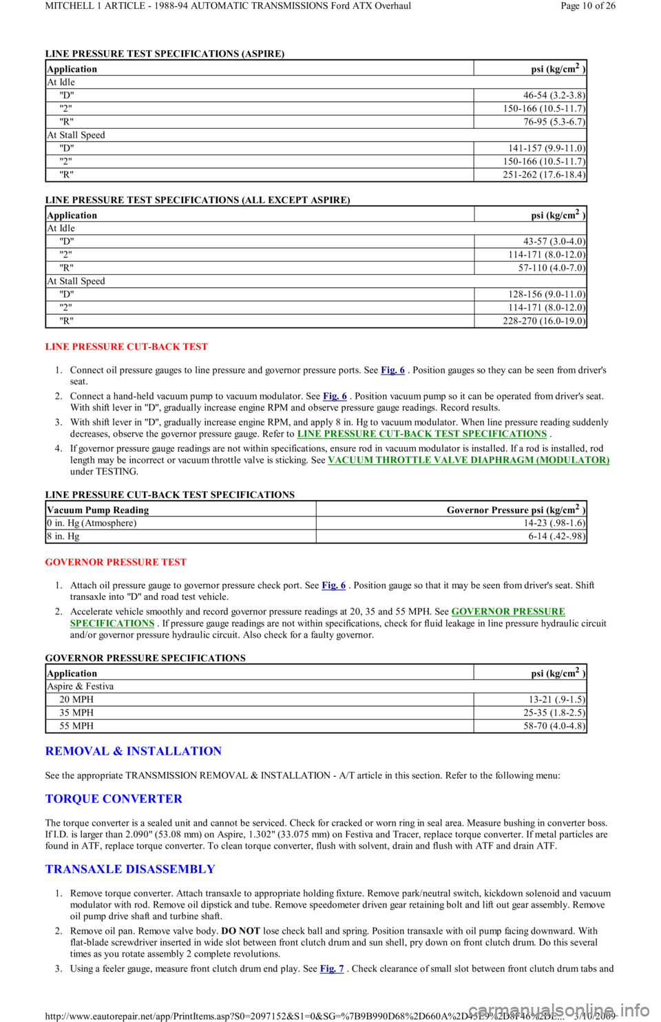
LINE PRESSURE TEST SPECIFICATIONS (ASPIRE)
LINE PRESSURE TEST SPECIFICATIONS (ALL EXCEPT ASPIRE)
LINE PRESSURE CUT-BACK TEST
1. Connect oil pressure gauges to line pressure and governor pressure ports. See Fig. 6
. Position gauges so they can be seen from driver's
seat.
2. Connect a hand-held vacuum pump to vacuum modulator. See Fig. 6
. Position vacuum pump so it can be operated from driver's seat.
With shift lever in "D", gradually increase engine RPM and observe pressure gauge readings. Record results.
3. With shift lever in "D", gradually increase engine RPM, and apply 8 in. Hg to vacuum modulator. When line pressure reading suddenly
decreases, observe the governor pressure gauge. Refer to LINE PRESSURE CUT
-BACK TEST SPECIFICATIONS .
4. If governor pressure gauge readings are not within specifications, ensure rod in vacuum modulator is installed. If a rod is installed, rod
length may be incorrect or vacuum throttle valve is sticking. See VACUUM THROTTLE VALVE DIAPHRAGM (MODULATOR)
under TESTING.
LINE PRESSURE CUT-BACK TEST SPECIFICATIONS
GOVERNOR PRESSURE TEST
1. Attach oil pressure gauge to governor pressure check port. See Fig. 6
. Position gauge so that it may be seen from driver's seat. Shift
transaxle into "D" and road test vehicle.
2. Accelerate vehicle smoothly and record governor pressure readings at 20, 35 and 55 MPH. See GOVERNOR PRESSURE
SPECIFICATIONS . If pressure gauge readings are not within specifications, check for fluid leakage in line pressure hydraulic circuit
and/or governor pressure hydraulic circuit. Also check for a faulty governor.
GOVERNOR PRESSURE SPECIFICATIONS
REMOVAL & INSTALLATION
See the appropriate TRANSMISSION REMOVAL & INSTALLATION - A/T article in this section. Refer to the following menu:
TORQUE CONVERTER
The torque converter is a sealed unit and cannot be serviced. Check for cracked or worn ring in seal area. Measure bushing in converter boss.
If I.D. is larger than 2.090" (53.08 mm) on Aspire, 1.302" (33.075 mm) on Festiva and Tracer, replace torque converter. If metal particles are
found in ATF, replace torque converter. To clean torque converter, flush with solvent, drain and flush with ATF and drain ATF.
TRANSAXLE DISASSEMBLY
1. Remove torque converter. Attach transaxle to appropriate holding fixture. Remove park/neutral switch, kickdown solenoid and vacuum
modulator with rod. Remove oil dipstick and tube. Remove speedometer driven gear retaining bolt and lift out gear assembly. Remove
oil pump drive shaft and turbine shaft.
2. Remove oil pan. Remove valve body. DO NOT lose check ball and spring. Position transaxle with oil pump facing downward. With
flat-blade screwdriver inserted in wide slot between front clutch drum and sun shell, pry down on front clutch drum. Do this seve r a l
times as you rotate assembly 2 complete revolutions.
3. Using a feeler gauge, measure front clutch drum end play. See Fig. 7
. Check clearance of small slot between front clutch drum tabs and
Applicationpsi (kg/cm2 )
At Idle
"D"46-54 (3.2-3.8)
"2 "150-166 (10.5-11.7)
"R"76-95 (5.3-6.7)
At Stall Speed
"D"141-157 (9.9-11.0)
"2 "150-166 (10.5-11.7)
"R"251-262 (17.6-18.4)
Applicationpsi (kg/cm2 )
At Idle
"D"43-57 (3.0-4.0)
"2 "114-171 (8.0-12.0)
"R"57-110 (4.0-7.0)
At Stall Speed
"D"128-156 (9.0-11.0)
"2 "114-171 (8.0-12.0)
"R"228-270 (16.0-19.0)
Vacuum Pump ReadingGovernor Pressure psi (kg/cm2 )
0 in. Hg (Atmosphere)14-23 (.98-1.6)
8 in. Hg6-14 (.42-.98)
Applicationpsi (kg/cm2 )
Aspire & Festiva
20 MPH13-21 (.9-1.5)
35 MPH25-35 (1.8-2.5)
55 MPH58-70 (4.0-4.8)
Page 10 of 26 MITCHELL 1 ARTICLE - 1988-94 AUTOMATIC TRANSMISSIONS Ford ATX Overhaul
3/10/2009 http://www.eautorepair.net/app/PrintItems.asp?S0=2097152&S1=0&SG=%7B9B990D68%2D660A%2D45E9%2D8F46%2DE
...
Page 432 of 454
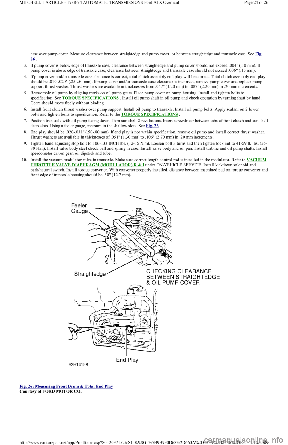
case over pump cover. Measure clearance between straightedge and pump cover, or between straightedge and transaxle case. See Fig.
26 .
3. If pump cover is below edge of transaxle case, clearance between straightedge and pump cover should not exceed .004" (.10 mm). If
pump cover is above edge of transaxle case, clearance between straightedge and transaxle case should not exceed .006" (.15 mm).
4. If pump cover and/or transaxle case clearance is correct, total clutch assembly end play will be correct. Total clutch assembly end play
should be .010-.020" (.25-.50 mm). If pump cover and/or transaxle case clearance is incorrect, remove pump cover and replace pump
support thrust washer. Thrust washers are available in thicknesses from .047" (1.20 mm) to .087" (2.20 mm) in .20 mm increments.
5. Reassemble oil pump by aligning marks on oil pump gears. Place pump cover on pump housing. Install and tighten bolts to
specification. See TORQUE SPECIFICATIONS
. Install oil pump shaft in oil pump and check operation by turning shaft by hand.
Gears should move freely without binding.
6. Install front clutch thrust washer over pump support. Install oil pump to transaxle. Install oil pump bolts. Apply sealant on 2 lower
bolts and tighten bolts to specification. Refer to the TORQUE SPECIFICATIONS
.
7. Position transaxle with oil pump facing down. Turn sun shell 2 revolutions. Insert screwdriver between tabs of front clutch and sun shell
deep slots. Using a feeler gauge, measure in the shallow slots. See Fig. 26
.
8. End play should be .020-.031" (.50-.80 mm). If end play is not within specification, remove oil pump and install correct thrust washer.
Thrust washers are available in thicknesses of .051" (1.30 mm) to .106" (2.70 mm) in .20 mm increments.
9. Tighten band adjusting stop bolt to 106-133 INCH lbs. (12-15 N.m). Loosen bolt 3 turns and then tighten lock nut to 41-59 ft. lbs. (56-
80 N.m). Install valve body steel check ball and spring in case. Install valve body and oil pan. Install turbine and oil pump sh aft s. In st al l
speedometer driven gear, oil dipstick and tube.
10. Install the vacuum modulator valve in transaxle. Make sure correct length control rod is installed in the modulator. Refer to VACUUM
THROTTLE VALVE DIAPHRAGM (MODULATOR) R & I under ON-VEHICLE SERVICE. Install kickdown solenoid and
park/neutral switch. Install torque converter. With converter properly installed, distance between machined pad on torque converter and
front edge of transaxle housing should be .50" (12.7 mm).
Fig. 26: Measuring Front Drum & Total End Play
Courtesy of FORD MOTOR CO.
Page 24 of 26 MITCHELL 1 ARTICLE - 1988-94 AUTOMATIC TRANSMISSIONS Ford ATX Overhaul
3/10/2009 http://www.eautorepair.net/app/PrintItems.asp?S0=2097152&S1=0&SG=%7B9B990D68%2D660A%2D45E9%2D8F46%2DE
...
Page 436 of 454
Back To Article
T RANSMISSION SERVICING - A/T
1988-93 T RANSMISSION SERVICING Ford Motor Co. Autom atic T ransm ission
IDENTIFICATION
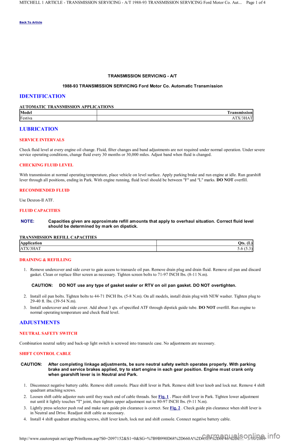
AUTOMATIC TRANSMISSION APPLICATIONS
LUBRICATION
SERVICE INTERVALS
Check fluid level at every engine oil change. Fluid, filter changes and band adjustments are not required under normal operation. Under severe
service operating conditions, change fluid every 30 months or 30,000 miles. Adjust band when fluid is changed.
CHECKING FLUID LEVEL
With transmission at normal operating temperature, place vehicle on level surface. Apply parking brake and run engine at idle. Run gearshift
lever through all positions, ending in Park. With engine running, fluid level should be between "F" and "L" marks. DO NOT overfill.
RECOMMENDED FLUID
Use Dexron-II ATF.
FLUID CAPACITIES
TRANSMISSION REFILL CAPACITIES
DRAINING & REFILLING
1. Remove undercover and side cover to gain access to transaxle oil pan. Remove drain plug and drain fluid. Remove oil pan and discard
gasket. Clean or replace filter screen as necessary. Tighten screen bolts to 71-97 INCH lbs. (8-11 N.m).
2. Install oil pan bolts. Tighten bolts to 44-71 INCH lbs. (5-8 N.m). On all models, install drain plug with NEW washer. Tighten plug to
29-40 ft. lbs. (39-54 N.m).
3. Install undercover and side cover. Add about 3 qts. of specified ATF through dipstick guide tube. DO NOT overfill. Run engine to
normal operating temperature and check fluid level.
ADJUSTMENTS
NEUTRAL SAFETY SWITCH
Combination neutral safety and back-up light switch is screwed into transaxle case. No adjustments are necessary.
SHIFT CONTROL CABLE
1. Disconnect negative battery cable. Remove shift console. Place shift lever in Park. Remove shift lever knob and lock nut. Remove 4 shift
quadrant attaching screws.
2. Loosen shift cable adjuster nuts until they reach end of cable threads. See Fig. 1
. Place shift lever in Park. Tighten lower adjustment
nut until it lightly touches "T" joint, then tighten upper adjustment nut to 80-97 INCH lbs. (9-11 N.m).
3. Lightly press selector push rod and make sure guide pin clearance is correct. See Fig. 2
. Check guide pin clearance when shift lever is
in Neutral and Drive. Readjust shift cable as necessary.
4. Install 4 shift quadrant attaching screws, shift lever knob, lock nut and shift console. Connect negative battery cable.
ModelTransmission
FestivaATX/3HAT
NOTE:Capacities given are approxim ate refill am ounts that apply to overhaul situation. Correct fluid level
should be determ ined by m ark on dipstick.
ApplicationQts. (L)
ATX/3HAT5.6 (5.3)
CAUT ION: DO NOT use any type of gasket sealer or RT V on oil pan gasket. DO NOT overtighten.
CAUT ION: After com pleting linkage adjustm ents, be sure neutral safety switch operates properly. With parking
brake and service brakes applied, try to start engine in each gear position. Engine m ust crank only
when gearshift lever is in Neutral and Park.
Page 1 of 4 MITCHELL 1 ARTICLE - TRANSMISSION SERVICING - A/T 1988-93 TRANSMISSION SERVICING Ford Motor Co. Aut
...
3/10/2009 http://www.eautorepair.net/app/PrintItems.asp?S0=2097152&S1=0&SG=%7B9B990D68%2D660A%2D45E9%2D8F46%2DE
...