1990 VOLKSWAGEN CORRADO warning
[x] Cancel search: warningPage 581 of 906

HEATER SYSTEM
Article Text
1990 Volkswagen Corrado
For Volkswagen Technical Site: http://vw.belcom.ru
Copyright © 1998 Mitchell Repair Information Company, LLC
Thursday, March 23, 2000 09:45PM
ARTICLE BEGINNING
1990 HEATER SYSTEMS
Volkswagen
Cabriolet, Corrado, Fox, Golf GL, GTI, Jetta,
Jetta GLi, Vanagon
WARNING: To avoid accidental air bag deployment, see AIR BAG
DEACTIVATION SERVICING PRECAUTIONS in this article.
DESCRIPTION
The heater is a water-valve type that combines heating,
defrosting and ventilation into one unit. Controls include fan control
knob and air distribution and temperature control levers. Blower fan
provides 3 speeds.
NOTE: Vanagon heater system information is not available from
manufacturer. For wiring diagram information, see WIRING
DIAGRAMS at end of this article.
OPERATION
When air distribution lever (upper lever) is in the center
stop position and lower temperature control lever is to the far left,
no air enters vehicle. As air distribution lever is moved to the left,
air is directed to floor vents. As distribution lever is moved to the
right, air is directed to defroster vents.
As heater lever (lower lever) is moved to the right, heater
turns on and heat output is increased. As the fan control knob is
turned to the right, the fan turns on and can be switched across its 3
speeds.
AIR BAG DEACTIVATION SERVICING PRECAUTIONS
WARNING: Some models are equipped with driver's side air bag
restraint system. Air bag-equipped vehicles have AIRBAG
stamped on the steering wheel horn pad. Air bag system
capacitor maintains a voltage charge sufficient to cause air
bag deployment for up to 20 MINUTES after ignition switch is
turned off and battery is disconnected.
DISABLING SYSTEM
Ensure ignition switch is OFF. Disconnect negative battery
cable and insulate terminal. Wait at least 20 MINUTES before
proceeding with repairs.
SYSTEM FUNCTIONAL CHECK
Page 603 of 906
INSTRUMENT PANEL
Article Text
1990 Volkswagen Corrado
For Volkswagen Technical Site: http://vw.belcom.ru
Copyright © 1998 Mitchell Repair Information Company, LLC
Thursday, March 23, 2000 09:46PM
ARTICLE BEGINNING
1989-90 ACCESSORIES & EQUIPMENT
Volkswagen Instrument Panels
Cabriolet, Fox, Golt, GTI, Jetta, Jetta GLI, Vanagon
DESCRIPTION & OPERATION
Instrument cluster for most models includes speedometer, fuel
gauge and temperature gauge. Optional instruments include clock,
tachometer, voltmeter and oil temperature gauge.
Printed circuit provides voltage to gauges. A voltage
regulator attached to the printed circuit controls voltage to fuel and
temperature gauges. Light Emitting Diodes (LEDs) are used for most
warning lights. To replace diodes, pull from printed circuit sockets.
NOTE: Volkswagen Tester (1301) is required for resistance tests.
Tester settings are numerical. Settings do not indicate
resistance in ohms. Manufacturer does not supply resistance
value in ohms.
TESTING
FUEL & TEMPERATURE GAUGE
1) Disconnect wire from fuel tank or temperature sending
unit. Connect VW tester between wire and ground. Turn ignition on and
allow 2 minutes for gauge reading to stabilize. Use FUEL GAUGE TESTING
or TEMPERATURE GAUGE TESTING table to compare gauge reading. Gauge
should be within one pointer width of specification.
2) If gauge needle does not move, check continuity between
sender wire and gauge. If needle moves, but does not match
specifications, replace gauge. If gauge works correctly with tester,
but not sending unit, replace sending unit.
FUEL GAUGE TESTINGÄÄÄÄÄÄÄÄÄÄÄÄÄÄÄÄÄÄÄÄÄÄÄÄÄÄÄÄÄÄÄÄÄÄÄÄÄÄÄÄÄÄÄÄÄÄÄÄÄÄÄÄÄÄÄApplication Dial Setting Indicator
Cabriolet & Fox .......... 55 ................ Full
560 ................Empty
Golf, GTI, Jetta
& Jetta GLI .............. 52 ................ Full
550 ................Empty
Vanagon .................. 50 ................ Full
320 ................Empty
ÄÄÄÄÄÄÄÄÄÄÄÄÄÄÄÄÄÄÄÄÄÄÄÄÄÄÄÄÄÄÄÄÄÄÄÄÄÄÄÄÄÄÄÄÄÄÄÄÄÄÄÄÄÄÄTEMPERATURE GAUGE TESTING
ÄÄÄÄÄÄÄÄÄÄÄÄÄÄÄÄÄÄÄÄÄÄÄÄÄÄÄÄÄÄÄÄÄÄÄÄÄÄÄÄÄÄÄÄÄÄÄÄÄÄÄÄÄÄÄ
Page 605 of 906
INSTRUMENT PANEL
Article Text (p. 3)
1990 Volkswagen Corrado
For Volkswagen Technical Site: http://vw.belcom.ru
Copyright © 1998 Mitchell Repair Information Company, LLC
Thursday, March 23, 2000 09:46PM
Removal & Installation
Disconnect negative battery cable. Remove steering wheel.
Pull tilt shelf downward. Remove 3 shelf retaining screws and remove
shelf. Remove 3 instrument panel lower retaining screws and and pry
off 3 clips. Remove 2 instrument trim retaining screws and remove
instrument panel trim. Remove center instrument cluster screw and tip
instrument panel cluster forward. Remove speedometer cable and wiring
connector from back of cluster. Remove instrument panel cluster. To
install, reverse removal procedure.
INSTRUMENT CLUSTER - FOX
Removal & Installation
Disconnect negative battery cable. Remove steering wheel.
Carefully remove covers from vacant switch position. Depress switch
spring retainer and remove switches from instrument panel. Disconnect
wire connectors from switches. Remove 4 instrument cluster trim
retaining screws. Remove instrument cluster trim panel. Remove 2
instrument cluster retaining screws. Remove speedometer cable.
Disconnect cluster wire connector and remove instrument cluster. To
install, reverse removal procedure.
INSTRUMENT CLUSTER - GOLF, GTI, JETTA & JETTA GLI
Removal & Installation
Remove temperature control knobs, levers and trim plate.
Remove radio or convenience tray. Remove switches from instrument
panel trim plate. Remove instrument panel trim plate. Remove 2
mounting screws and pull instrument cluster outward. Remove
speedometer cable, vacuum hoses, and electrical connections. To
install, reverse removal procedures.
INSTRUMENT CLUSTER - VANAGON
Removal & Installation
Disconnect negative battery cable. Reach behind cluster hood
and pull back of hood upward. Pull hazard switch forward. Pull brake
warning light housing toward front of vehicle. Remove 4 mounting
screws and remove cluster. To install, reverse removal procedure.
COMBINATION SWITCH
Removal
Remove steering wheel. Remove column cover. Disconnect wiring
and remove 3 switch screws. Remove switches.
Installation
Install switches on column. Place steering wheel on column
and ensure clearance between wheel and turn signal switch is 1/16-
1/8". Move spacer sleeve up or down to adjust clearance. Tighten
steering wheel nut to 36 ft. lbs. (50 N.m) and replace pad.
Page 647 of 906
MAINTENANCE INFORMATION
Article Text (p. 12)
1990 Volkswagen Corrado
For Volkswagen Technical Site: http://vw.belcom.ru
Copyright © 1998 Mitchell Repair Information Company, LLC
Thursday, March 23, 2000 09:48PM
of 650 amps.
CAUTIONS & WARNINGS
CAUTION: Contact with live components of ignition system while
engine is running could lead to a fatal electric shock.
CAUTION: Brake pedal requires extreme pressure to stop vehicle when
engine is not running.
WARRANTY INFORMATION
CAUTION: Always refer to customer's copy of warranty information for
specific model application and/or coverage limitations.
BASIC NEW CAR WARRANTY
Manufacturer warrants to the original retail customer, and
any subsequent purchaser, that every vehicle imported and sold as a
new vehicle to a retail customer will be free of defects in material
and workmanship for 2 years or 24,000 miles, whichever comes first,
after date of delivery to the first retail customer, or after vehicle
was first placed in service.
LIMITED WARRANTY
Warrants cars to be free of defects in materials or
workmanship for a period of 2 years or 24,000 miles, whichever comes
first.
LIMITED POWER TRAIN WARRANTY
Covers engine, transmission and drivetrain for a period of 5
years or 50,000 miles, whichever occurs first.
ANTI-CORROSION
Covers holes caused by corrosion in body sheet metal for 6
years, without respect to mileage, so long as inspection and
maintenance services are performed.
EMISSION CONTROL SYSTEM
Manufacturer warrants to the initial purchaser and each
subsequent purchaser that this vehicle is designed, built, and
equipped so as to conform at the time of sale with all U.S. and
California Air Resources Board emission regulations applicable at the
time of manufacture, and that this vehicle is free from defects in
materials and workmanship which cause it to fail to conform with
applicable regulations within the first 5 years or 50,000 miles,
whichever occurs first.
Page 648 of 906
MAINTENANCE INFORMATION
Article Text (p. 13)
1990 Volkswagen Corrado
For Volkswagen Technical Site: http://vw.belcom.ru
Copyright © 1998 Mitchell Repair Information Company, LLC
Thursday, March 23, 2000 09:48PM
FUSES & CIRCUIT BREAKERS
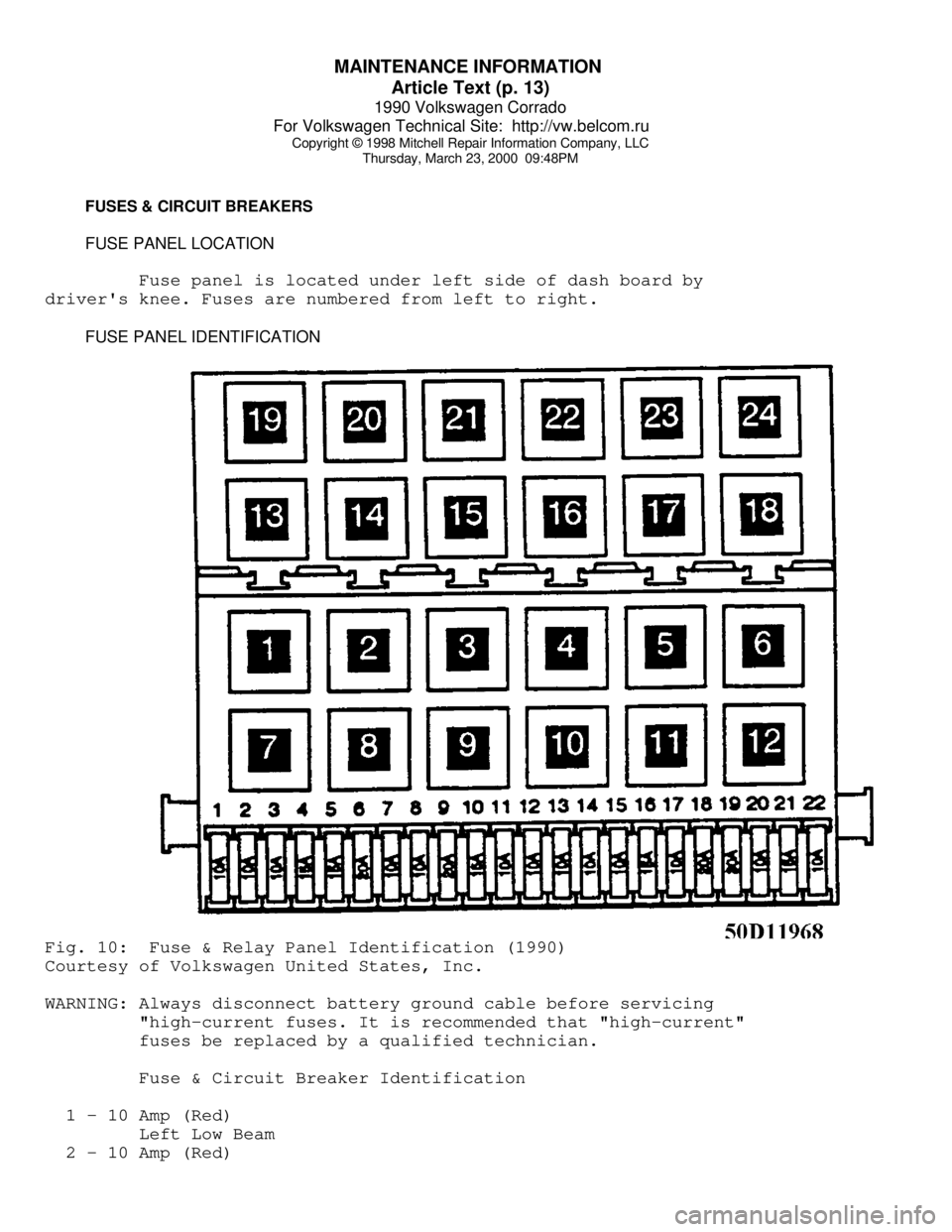
FUSE PANEL LOCATION
Fuse panel is located under left side of dash board by
driver's knee. Fuses are numbered from left to right.
FUSE PANEL IDENTIFICATIONFig. 10: Fuse & Relay Panel Identification (1990)
Courtesy of Volkswagen United States, Inc.
WARNING: Always disconnect battery ground cable before servicing
"high-current fuses. It is recommended that "high-current"
fuses be replaced by a qualified technician.
Fuse & Circuit Breaker Identification
1 - 10 Amp (Red)
Left Low Beam
2 - 10 Amp (Red)
Page 649 of 906
MAINTENANCE INFORMATION
Article Text (p. 14)
1990 Volkswagen Corrado
For Volkswagen Technical Site: http://vw.belcom.ru
Copyright © 1998 Mitchell Repair Information Company, LLC
Thursday, March 23, 2000 09:48PM
Right Low Beam
3 - 10 Amp (Red)
Instrument Lights, License Plate Lights
4 - 15 Amp (Blue)
Rear Window Wiper, Sliding Roof
5 - 15 Amp (Blue)
Windshield & Rear Window Washer, Windshield Wiper
6 - 20 Amp (Yellow)
Air Conditioner, Fresh Air Fan
7 - 10 Amp (Red)
Right Tail & Side Lights
8 - 10 Amp (Red)
Left Tail & Side Lights
9 - 20 Amp (Yellow)
Rear Window Defroster, Mirror Heating
10 - 15 Amp (Blue)
Foglights
11 - 10 Amp (Red)
Left High Beam, High Beam Indicator
12 - 10 Amp (Red)
Right High Beam
13 - 10 Amp (Red)
Horn, Radiator Fan
14 - 15 Amp (Blue)
Back-Up Lights, Electric Mirrors, Heated Washer Jets
15 - 10 Amp (Red)
Electronic Ignition, Idle Stabilizer,
Deceleration Fuel Shut Off
16 - 15 Amp (Blue)
Warning/Indicator Lights, Multi-Function Indicator, Glove Box
Light, Cassette Storage Light, Rear Spoiler Control Unit
17 - 10 Amp (Red)
Emergency Flashers, Turn Signals
18 - 20 Amp (Yellow)
Fuel Pump, Heated Oxygen Sensor
19 - 30 Amp (Green)
Radiator Fan, Air Conditioner
20 - 10 Amp (Red)
Brake Lights, Cruise Control
21 - 15 Amp (Blue)
Interior Compartment Lights, Cigarette Lighter, Digital Clock
Central Locking System, Rear Spoiler Adjustment
22 - 10 Amp (Red)
Radio
Relay & Circuit Breaker Identification
1 - A/C Control Module Relay
2 - Rear Window Wiper/Washer Relay
3 - ECM Power Supply Relay
4 - Load Reduction Relay
5 - Low Coolant Level
Page 650 of 906

MAINTENANCE INFORMATION
Article Text (p. 15)
1990 Volkswagen Corrado
For Volkswagen Technical Site: http://vw.belcom.ru
Copyright © 1998 Mitchell Repair Information Company, LLC
Thursday, March 23, 2000 09:48PM
6 - Emergency Flasher Relay
7 - Not Used
8 - Washer/Wiper Intermittent Relay
9 - Seat Belt Warning Control Module
10 - Fog Lamp/Parking Lamp Relay
11 - Dual Horn Relay
12 - Fuel Pump Relay
13 - ABS Hydraulic Pump Relay
14 - ABS Relay
15 - Radiator After Run Relay
16 - Fuel Pump After Run Control Unit
17 - Heated Driver Seat Relay
18 - Heated Passenger Seat Relay
19 - ABS Hydraulic Pump Fuse (30 Amp)
20 - ABS Hydraulic Valve Fuse (30 Amp)
21 - Power Window Fuse (20 Amp)
22 - ABS Valves Fuse (30 Amp)
23 - Not Used
24 - Not UsedFig. 11: Fuse & Relay Panel ID (1991-92)
Courtesy of Volkswagen United States, Inc.
Page 651 of 906
MAINTENANCE INFORMATION
Article Text (p. 16)
1990 Volkswagen Corrado
For Volkswagen Technical Site: http://vw.belcom.ru
Copyright © 1998 Mitchell Repair Information Company, LLC
Thursday, March 23, 2000 09:48PM
WARNING: Always disconnect battery ground cable before servicing
"high-current fuses. It is recommended that "high-current"
fuses be replaced by a qualified technician.
Fuse & Circuit Breaker Identification
1 - 10 Amp (Red)
Left Low Beam
2 - 10 Amp (Red)
Right Low Beam
3 - 10 Amp (Red)
Instrument Lights, License Plate Lights
4 - 15 Amp (Blue)
Rear Window Wiper, Sliding Roof
5 - 15 Amp (Blue)
Windshield & Rear Window Washer, Windshield Wiper
6 - 20 Amp (Yellow)
Air Conditioner, Fresh Air Fan
7 - 10 Amp (Red)
Right Tail & Side Lights
8 - 10 Amp (Red)
Left Tail & Side Lights
9 - 20 Amp (Yellow)
Rear Window Defroster, Mirror Heating
10 - 15 Amp (Blue)
Foglights
11 - 10 Amp (Red)
Left High Beam, High Beam Indicator
12 - 10 Amp (Red)
Right High Beam
13 - 10 Amp (Red)
Horn, Radiator Fan
14 - 15 Amp (Blue)
Back-Up Lights, Electric Mirrors, Heated Washer Jets
15 - 10 Amp (Red)
Electronic Ignition, Idle Stabilizer,
Deceleration Fuel Shut Off
16 - 15 Amp (Blue)
Warning/Indicator Lights, Multi-Function Indicator, Glove Box
Light, Cassette Storage Light, Rear Spoiler Control Unit
17 - 10 Amp (Red)
Emergency Flashers, Turn Signals
18 - 20 Amp (Yellow)
Fuel Pump, Heated Oxygen Sensor
19 - 30 Amp (Green)
Radiator Fan, Air Conditioner
20 - 10 Amp (Red)
Brake Lights, Cruise Control
21 - 15 Amp (Blue)
Dome & Luggage Compartment Lights, Cigarette Lighter, Clock
Central Locking System, Multi-Function Indicator,
Rear Spoiler Adjustment, Engine Diagnostic