1990 VOLKSWAGEN CORRADO oil type
[x] Cancel search: oil typePage 598 of 906

I - SYSTEM/COMPONENT TESTS
Article Text (p. 11)
1990 Volkswagen Corrado
For Volkswagen Technical Site: http://vw.belcom.ru
Copyright © 1998 Mitchell Repair Information Company, LLC
Thursday, March 23, 2000 09:46PM
okay, check ground circuit through thermo time switch. Replace thermo
time switch if contact to ground cannot be made.
IDLE CONTROL SYSTEM
NOTE: Knock control is integral in AFC-Digifant II ECU.
KNOCK SENSOR CONTROL UNIT (ALL MODELS EXCEPT VANAGON)
1) Check ignition coil and Hall Effect sender before checking
knock sensor control unit. Remove knock sensor control unit harness
connector. Turn ignition on. Using a voltmeter, check for battery
voltage between terminals No. 3 and No. 5 and terminals No. 6 and No.
3 of knock sensor control unit. Open throttle valve. Voltage should
drop to zero volts.
2) If voltage does not drop to zero volts, check throttle
valve switch (full throttle). Check voltage between terminals No. 8
and No. 3, while fully opening throttle valve. If battery voltage was
not present when throttle fully open, replace throttle valve switch.
See Fig. 13.
3) Remove Hall Effect sender connector and connect voltmeter
to outside terminals. Turn ignition on. There should be 5 volts
present. Turn ignition off. Connect voltmeter between terminals No. 1
(negative) and No. 15 (positive) of ignition coil. Turn ignition on
and touch center terminal of Hall Effect sender briefly to ground.
Voltage should jump momentarily to approximately 2 volts. If voltage
does not jump, replace knock sensor control unit.
KNOCK SENSOR(S)
Before replacing knock sensor, check knock sensor torque and
resistance. Remove knock sensor connector and check resistance between
terminals No. 13 and No. 14. See KNOCK SENSOR TORQUE & RESISTANCE
SPECIFICATION table. If resistance is incorrect, replace knock sensor.
NOTE: Knock sensor mounting bolt torque must be exact. DO NOT use
washers when mounting knock sensor.
KNOCK SENSOR RESISTANCE & TORQUE SPECIFICATIONÄÄÄÄÄÄÄÄÄÄÄÄÄÄÄÄÄÄÄÄÄÄÄÄÄÄÄÄÄÄÄÄÄÄÄÄÄÄÄÄÄÄÄÄÄÄÄÄÄÄÄÄÄÄÄÄÄÄÄÄÄÄÄÄÄÄÄÄÄÄApplication Resistance Ft. Lbs (N.m)
Type I ...................... 300,000 ................ 7-9 (10-12)
Type II .................... Infinite .............. 15-18 (20-25)
ÄÄÄÄÄÄÄÄÄÄÄÄÄÄÄÄÄÄÄÄÄÄÄÄÄÄÄÄÄÄÄÄÄÄÄÄÄÄÄÄÄÄÄÄÄÄÄÄÄÄÄÄÄÄÄÄÄÄÄÄÄÄÄÄÄÄÄÄÄÄ IDLE STABILIZATION SYSTEM (VANAGON)
1) Attach Test Meter (VW 1315/2) and Adapter (US 1119) to
idle stabilization valve. Set meter to milliampere scale. Start
engine. Observe test meter while turning A/C control switch to ON
position. If milliampere reading increases, system is okay.
Page 728 of 906

STARTER - BOSCH
Article Text
1990 Volkswagen Corrado
For Volkswagen Technical Site: http://vw.belcom.ru
Copyright © 1998 Mitchell Repair Information Company, LLC
Thursday, March 23, 2000 09:51PM
ARTICLE BEGINNING
1990-92 ELECTRICAL
Starters - Bosch
1990-92 Passat
1991-92 Cabriolet, Corrado, Fox, Golf GL, GTI, Jetta, Vanagon
DESCRIPTION
Starter is a brush type, series-wound electric motor with an
overrunning clutch. Field frame is enclosed by commutator end frame
and drive bushing and carries pole shoes and field coils. A splined
armature shaft drive end carries drive assembly.
TROUBLE SHOOTING
CHARGING SYSTEM TROUBLE SHOOTING TABLEÄÄÄÄÄÄÄÄÄÄÄÄÄÄÄÄÄÄÄÄÄÄÄÄÄÄÄÄÄÄÄÄÄÄÄÄÄÄÄÄÄÄÄÄÄÄÄÄÄÄÄÄÄÄÄÄÄÄÄÄÄÄÄÄÄPROBLEM
Possible Cause Action
ÄÄÄÄÄÄÄÄÄÄÄÄÄÄÄÄÄÄÄÄÄÄÄÄÄÄÄÄÄÄÄÄÄÄÄÄÄÄÄÄÄÄÄÄÄÄÄÄÄÄÄÄÄÄÄÄÄÄÄÄÄÄÄÄÄNO START CONDITION
Dead Battery ............................ Check/Replace Battery
Bad Cable Connections .................... Clean/Replace Cables
Ignition Switch/Circuit Fault ............ Check Switch/Circuit
CHARGING SYSTEM WARNING LIGHT STAYS ON
Loose/Worn Alternator Belt ............... Tighten/Replace Belt
Loose Alternator Connections ......... Check/Repair Connections
Warning Light Wiring ...................... Check/Repair Wiring
Faulty Stator/Diodes ................... Test/Repair Alternator
Faulty Voltage Regulator ................ Test/Repair Regulator
WARNING LIGHT OFF WITH IGNITION SWITCH ON
Blown Fuse ................................. Check/Replace Fuse
Faulty Alternator ............................. Test Alternator
Bad Warning Light Bulb ...................... Test/Replace Bulb
WARNING LIGHT ON WITH IGNITION SWITCH OFF
Alternator Wiring Short ................... Check/Repair Wiring
Faulty Rectifier Bridge ................ Test/Repair Alternator
AMMETER INDICATES DISCHARGE
Loose/Worn Alternator Belt ............... Tighten/Replace Belt
Loose Alternator Connections ......... Check/Repair Connections
Page 748 of 906

STEERING SYSTEM - POWER
Article Text
1990 Volkswagen Corrado
For Volkswagen Technical Site: http://vw.belcom.ru
Copyright © 1998 Mitchell Repair Information Company, LLC
Thursday, March 23, 2000 09:51PM
ARTICLE BEGINNING
1990-92 STEERING
Volkswagen - Power Rack & Pinion
1990-92 Passat
1991-92 Cabriolet, Corrado, Golf, GTI, Jetta, Vanagon
DESCRIPTION & OPERATION
System consists of a vane pump, rack and pinion steering
gear, and an oil reservoir. Vane pump draws fluid from reservoir and
supplies it to flow control valve. Control valve directs fluid to
appropriate side of rack piston.
LUBRICATION
CAPACITY
Fluid capacity is approximately 1 qt. (.95L).
FLUID TYPE
On all models, the recommended fluid type is V.W. Hydraulic
Oil (G 002 000).
FLUID LEVEL CHECK
Remove reservoir cover. Start engine and let idle. Fluid
level should be between MIN and MAX marks on reservoir.
HYDRAULIC SYSTEM BLEEDING
1) Start engine and let idle. Ensure fluid is at proper
level. Turn steering wheel from lock to lock several times quickly.
2) Continue until fluid level remains at reservoir mark.
Ensure no bubbles appear in reservoir when steering wheel is turned.
Shut off engine. Ensure oil level does not rise more than 3/8" (10
mm).
Page 831 of 906

TROUBLE SHOOTING - BASIC PROCEDURES
Article Text (p. 55)
1990 Volkswagen Corrado
For Volkswagen Technical Site: http://vw.belcom.ru
Copyright © 1998 Mitchell Repair Information Company, LLC
Thursday, March 23, 2000 09:52PM
Faulty choke Replace choke
assembly, see ENGINE
PERFORMANCE section
Clogged air filter Clean and/or replace
air filter
Incorrect idle speed or Reset idle speed and/
dirty carburetor or clean carburetor
Faulty ignition wires Replace ignition
wiring
Prolonged operation Shut engine off
at idle during long idle
Sticking valves or worn Check valve train
valve guide sealsÄÄÄÄÄÄÄÄÄÄÄÄÄÄÄÄÄÄÄÄÄÄÄÄÄÄÄÄÄÄÄÄÄÄÄÄÄÄÄÄÄÄÄÄÄÄÄÄÄÄÄÄÄÄÄÄÄÄÄÄÄÄÄÄÄÄÄÄÄÄWet Fouling Worn rings and pistons Install new rings and
or Oil Deposits pistons
Excessive cylinder wear Rebore or replace
block
Excessive valve guide Worn or loose bearing
clearance
ÄÄÄÄÄÄÄÄÄÄÄÄÄÄÄÄÄÄÄÄÄÄÄÄÄÄÄÄÄÄÄÄÄÄÄÄÄÄÄÄÄÄÄÄÄÄÄÄÄÄÄÄÄÄÄÄÄÄÄÄÄÄÄÄÄÄÄÄÄÄGap Bridged Deposits in combustion Clean combustion
chamber becoming fused chamber of deposits
to electrode
ÄÄÄÄÄÄÄÄÄÄÄÄÄÄÄÄÄÄÄÄÄÄÄÄÄÄÄÄÄÄÄÄÄÄÄÄÄÄÄÄÄÄÄÄÄÄÄÄÄÄÄÄÄÄÄÄÄÄÄÄÄÄÄÄÄÄÄÄÄÄBlistered Engine overheating Check cooling system
Electrode
Wrong type of fuel Replace with correct
fuel
Loose spark plugs Retighten spark plugs
Over-advanced ignition Reset ignition timing
timing see ENGINE PERFORMANCE
ÄÄÄÄÄÄÄÄÄÄÄÄÄÄÄÄÄÄÄÄÄÄÄÄÄÄÄÄÄÄÄÄÄÄÄÄÄÄÄÄÄÄÄÄÄÄÄÄÄÄÄÄÄÄÄÄÄÄÄÄÄÄÄÄÄÄÄÄÄÄPre-Ignition or Incorrect type of fuel Replace with correct
Melted Electrodes fuel
Incorrect ignition timing Reset ignition timing
see ENGINE PERFORMANCE
Burned valves Replace valves
Engine Overheating Check cooling system
Page 852 of 906

WAVEFORMS - INJECTOR PATTERN TUTORIAL
Article Text (p. 8)
1990 Volkswagen Corrado
For Volkswagen Technical Site: http://vw.belcom.ru
Copyright © 1998 Mitchell Repair Information Company, LLC
Thursday, March 23, 2000 09:52PM
Here is one example. Imagine a vehicle that has a faulty
injector driver that occasionally skips an injector pulse. Every
skipped pulse means that that cylinder does not fire, thus unburned O2
gets pushed into the exhaust and passes the O2 sensor. The O2 sensor
indicates lean, so the computer fattens up the mixture to compensate
for the supposed "lean" condition.
A connected dwell/duty meter would see the fattened pulse
width but would also see the skipped pulses. It would tally both and
likely come back with a reading that indicated the "pulse width" was
within specification because the rich mixture and missing pulses
offset each other.
This situation is not a far-fetched scenario. Some early GM
3800 engines were suffering from exactly this. The point is that a
lack of detail could cause misdiagnosis.
As you might have guessed, a lab scope would not miss this.
RELATIONSHIP BETWEEN DWELL & DUTY CYCLE READINGS TABLE (1)ÄÄÄÄÄÄÄÄÄÄÄÄÄÄÄÄÄÄÄÄÄÄÄÄÄÄÄÄÄÄÄÄÄÄÄÄÄÄÄÄÄÄÄÄÄÄÄÄÄÄÄÄÄÄÄÄÄÄÄÄDwell Meter (2) Duty Cycle Meter
1
ø .................................................... 1%
15
ø .................................................. 25%
30
ø .................................................. 50%
45
ø .................................................. 75%
60
ø ................................................. 100%
(1) - These are just some examples for your understanding.
It is okay to fill in the gaps.
(2) - Dwell meter on the six-cylinder scale.
ÄÄÄÄÄÄÄÄÄÄÄÄÄÄÄÄÄÄÄÄÄÄÄÄÄÄÄÄÄÄÄÄÄÄÄÄÄÄÄÄÄÄÄÄÄÄÄÄÄÄÄÄÄÄÄÄÄÄÄÄ THE TWO TYPES OF INJECTOR DRIVERS
OVERVIEW
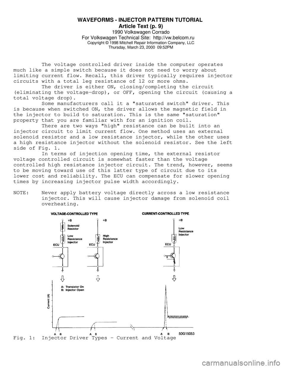
There are two types of transistor driver circuits used to
operate electric fuel injectors: voltage controlled and current
controlled. The voltage controlled type is sometimes called a
"saturated switch" driver, while the current controlled type is
sometimes known as a "peak and hold" driver.
The basic difference between the two is the total resistance
of the injector circuit. Roughly speaking, if a particular leg in an
injector circuit has total resistance of 12 or more ohms, a voltage
control driver is used. If less than 12 ohms, a current control driver
is used.
It is a question of what is going to do the job of limiting
the current flow in the injector circuit; the inherent "high"
resistance in the injector circuit, or the transistor driver. Without
some form of control, the current flow through the injector would
cause the solenoid coil to overheat and result in a damaged injector.
VOLTAGE CONTROLLED CIRCUIT ("SATURATED SWITCH")
Page 853 of 906
WAVEFORMS - INJECTOR PATTERN TUTORIAL
Article Text (p. 9)
1990 Volkswagen Corrado
For Volkswagen Technical Site: http://vw.belcom.ru
Copyright © 1998 Mitchell Repair Information Company, LLC
Thursday, March 23, 2000 09:52PM
The voltage controlled driver inside the computer operates
much like a simple switch because it does not need to worry about
limiting current flow. Recall, this driver typically requires injector
circuits with a total leg resistance of 12 or more ohms.
The driver is either ON, closing/completing the circuit
(eliminating the voltage-drop), or OFF, opening the circuit (causing a
total voltage drop).
Some manufacturers call it a "saturated switch" driver. This
is because when switched ON, the driver allows the magnetic field in
the injector to build to saturation. This is the same "saturation"
property that you are familiar with for an ignition coil.
There are two ways "high" resistance can be built into an
injector circuit to limit current flow. One method uses an external
solenoid resistor and a low resistance injector, while the other uses
a high resistance injector without the solenoid resistor. See the left
side of Fig. 1.
In terms of injection opening time, the external resistor
voltage controlled circuit is somewhat faster than the voltage
controlled high resistance injector circuit. The trend, however, seems
to be moving toward use of this latter type of circuit due to its
lower cost and reliability. The ECU can compensate for slower opening
times by increasing injector pulse width accordingly.
NOTE: Never apply battery voltage directly across a low resistance
injector. This will cause injector damage from solenoid coil
overheating.Fig. 1: Injector Driver Types - Current and Voltage