1990 VOLKSWAGEN CORRADO fuse box
[x] Cancel search: fuse boxPage 75 of 906

* ELECTRICAL SYSTEM UNIFORM INSPECTION GUIDELINES *
Article Text (p. 10)
1990 Volkswagen Corrado
For Volkswagen Technical Site: http://vw.belcom.ru
Copyright © 1998 Mitchell Repair Information Company, LLC
Thursday, March 23, 2000 09:29PM
WIRING HARNESS/CONNECTORS
VOLTAGE REGULATORÄÄÄÄÄÄÄÄÄÄÄÄÄÄÄÄÄÄÄÄÄÄÄÄÄÄÄÄÄÄÄÄÄÄÄÄÄÂÄÄÄÄÄÄÄÄÄÄÄÄÄÄÄÄÄÄÄÄÄÄÄÄÄÄÄÄÄÄÄÄCondition
³ Procedure
ÄÄÄÄÄÄÄÄÄÄÄÄÄÄÄÄÄÄÄÄÄÄÄÄÄÄÄÄÄÄÄÄÄÄÄÄÄÅÄÄÄÄÄÄÄÄÄÄÄÄÄÄÄÄÄÄÄÄÄÄÄÄÄÄÄÄÄÄÄÄRouted incorrectly
³ Suggest repair.
ÄÄÄÄÄÄÄÄÄÄÄÄÄÄÄÄÄÄÄÄÄÄÄÄÄÄÄÄÄÄÄÄÄÄÄÄÄÅÄÄÄÄÄÄÄÄÄÄÄÄÄÄÄÄÄÄÄÄÄÄÄÄÄÄÄÄÄÄÄÄShorted/open
³ Require repair or replacement.
ÄÄÄÄÄÄÄÄÄÄÄÄÄÄÄÄÄÄÄÄÄÄÄÄÄÄÄÄÄÄÄÄÄÄÄÄÄÅÄÄÄÄÄÄÄÄÄÄÄÄÄÄÄÄÄÄÄÄÄÄÄÄÄÄÄÄÄÄÄÄConnector terminal problem (e.g.,
³ Suggest repair or replacement.
bent, corroded, loose)
³
ÄÄÄÄÄÄÄÄÄÄÄÄÄÄÄÄÄÄÄÄÄÄÄÄÄÄÄÄÄÄÄÄÄÄÄÄÄÅÄÄÄÄÄÄÄÄÄÄÄÄÄÄÄÄÄÄÄÄÄÄÄÄÄÄÄÄÄÄÄÄExcessive resistance
³ Require repair or replacement.
ÄÄÄÄÄÄÄÄÄÄÄÄÄÄÄÄÄÄÄÄÄÄÄÄÄÄÄÄÄÄÄÄÄÄÄÄÄÅÄÄÄÄÄÄÄÄÄÄÄÄÄÄÄÄÄÄÄÄÄÄÄÄÄÄÄÄÄÄÄÄPoor ground
³ Require repair.
ÄÄÄÄÄÄÄÄÄÄÄÄÄÄÄÄÄÄÄÄÄÄÄÄÄÄÄÄÄÄÄÄÄÄÄÄÄÅÄÄÄÄÄÄÄÄÄÄÄÄÄÄÄÄÄÄÄÄÄÄÄÄÄÄÄÄÄÄÄÄDamaged
³ Suggest repair or replacement.
ÄÄÄÄÄÄÄÄÄÄÄÄÄÄÄÄÄÄÄÄÄÄÄÄÄÄÄÄÄÄÄÄÄÄÄÄÄÁÄÄÄÄÄÄÄÄÄÄÄÄÄÄÄÄÄÄÄÄÄÄÄÄÄÄÄÄÄÄÄÄ FUSE BOX/BLOCK
FUSE BOX/BLOCK
ÄÄÄÄÄÄÄÄÄÄÄÄÄÄÄÄÄÄÄÄÂÄÄÄÄÄÄÄÄÄÄÄÄÄÄÄÄÄÄÄÄÄÄÂÄÄÄÄÄÄÄÄÄÄÄÄÄÄÄÄÄÄÄÄÄÄÄÄÄÄCondition
³ Procedure ³ Note
ÄÄÄÄÄÄÄÄÄÄÄÄÄÄÄÄÄÄÄÄÅÄÄÄÄÄÄÄÄÄÄÄÄÄÄÄÄÄÄÄÄÄÄÅÄÄÄÄÄÄÄÄÄÄÄÄÄÄÄÄÄÄÄÄÄÄÄÄÄÄBurned/melted
³ Further inspection ³ Determine cause and
³ required. ³ correct prior to repair
³ ³ or replacement of fuse
³ ³ box.
ÄÄÄÄÄÄÄÄÄÄÄÄÄÄÄÄÄÄÄÄÅÄÄÄÄÄÄÄÄÄÄÄÄÄÄÄÄÄÄÄÄÄÄÅÄÄÄÄÄÄÄÄÄÄÄÄÄÄÄÄÄÄÄÄÄÄÄÄÄÄConnector, terminal
³ Suggest repair or ³problem (e.g., bent,
³ replacement. ³corroded, loose)
³ ³
ÄÄÄÄÄÄÄÄÄÄÄÄÄÄÄÄÄÄÄÄÅÄÄÄÄÄÄÄÄÄÄÄÄÄÄÄÄÄÄÄÄÄÄÅÄÄÄÄÄÄÄÄÄÄÄÄÄÄÄÄÄÄÄÄÄÄÄÄÄÄMissing, damaged
³ Require replacement ³mounting hardware
³ of mounting hardware.³
ÄÄÄÄÄÄÄÄÄÄÄÄÄÄÄÄÄÄÄÄÁÄÄÄÄÄÄÄÄÄÄÄÄÄÄÄÄÄÄÄÄÄÄÁÄÄÄÄÄÄÄÄÄÄÄÄÄÄÄÄÄÄÄÄÄÄÄÄÄÄ SYSTEM INDICATOR LIGHTS
SYSTEM INDICATOR LIGHTS
ÄÄÄÄÄÄÄÄÄÄÄÄÄÄÄÄÄÄÄÄÄÂÄÄÄÄÄÄÄÄÄÄÄÄÄÄÄÄÄÄÄÄÄÂÄÄÄÄÄÄÄÄÄÄÄÄÄÄÄÄÄÄÄÄÄÄÄÄÄÄCondition
³ Procedure ³ Note
ÄÄÄÄÄÄÄÄÄÄÄÄÄÄÄÄÄÄÄÄÄÅÄÄÄÄÄÄÄÄÄÄÄÄÄÄÄÄÄÄÄÄÄÅÄÄÄÄÄÄÄÄÄÄÄÄÄÄÄÄÄÄÄÄÄÄÄÄÄÄLight does not come
³ Further inspection ³ See service manual for
on during bulb check
³ required. ³ further information
ÄÄÄÄÄÄÄÄÄÄÄÄÄÄÄÄÄÄÄÄÄ´ ³Fail to function
³ ³properly during test
³ ³mode
³ ³
ÄÄÄÄÄÄÄÄÄÄÄÄÄÄÄÄÄÄÄÄÄ´
³
Page 84 of 906

* ELECTRICAL SYSTEM UNIFORM INSPECTION GUIDELINES *
Article Text (p. 19)
1990 Volkswagen Corrado
For Volkswagen Technical Site: http://vw.belcom.ru
Copyright © 1998 Mitchell Repair Information Company, LLC
Thursday, March 23, 2000 09:29PMÄÄÄÄÄÄÄÄÄÄÄÄÄÄÄÄÄÄÄÄÄÅÄÄÄÄÄÄÄÄÄÄÄÄÄÄÄÄÄÄÄÄÄÄÅÄÄÄÄÄÄÄÄÄÄÄÄÄÄÄÄÄÄÄÄÄÄÄÄÄOut of adjustment
³ Further inspection ³ Follow OEM recommended
³ required. ³ adjustment procedures.
³ ³ Repair or replace if out
³ ³ of specification.
ÄÄÄÄÄÄÄÄÄÄÄÄÄÄÄÄÄÄÄÄÄÅÄÄÄÄÄÄÄÄÄÄÄÄÄÄÄÄÄÄÄÄÄÄÅÄÄÄÄÄÄÄÄÄÄÄÄÄÄÄÄÄÄÄÄÄÄÄÄÄLeaking (vacuum/
³ Suggest repair or ³fluid/air)
³ replacement. ³
ÄÄÄÄÄÄÄÄÄÄÄÄÄÄÄÄÄÄÄÄÄ´
³Noisy
³ ³
ÄÄÄÄÄÄÄÄÄÄÄÄÄÄÄÄÄÄÄÄÄ´
³Corroded, loose
³ ³terminals
³ ³
ÄÄÄÄÄÄÄÄÄÄÄÄÄÄÄÄÄÄÄÄÄÅÄÄÄÄÄÄÄÄÄÄÄÄÄÄÄÄÄÄÄÄÄÄÅÄÄÄÄÄÄÄÄÄÄÄÄÄÄÄÄÄÄÄÄÄÄÄÄÄMissing, damaged
³ Require repair or ³mounting hardware
³ replacement of ³
³ mounting hardware. ³
ÄÄÄÄÄÄÄÄÄÄÄÄÄÄÄÄÄÄÄÄÄÅÄÄÄÄÄÄÄÄÄÄÄÄÄÄÄÄÄÄÄÄÄÄÅÄÄÄÄÄÄÄÄÄÄÄÄÄÄÄÄÄÄÄÄÄÄÄÄÄDamaged
³ Suggest repair or ³
³ replacement. ³
ÄÄÄÄÄÄÄÄÄÄÄÄÄÄÄÄÄÄÄÄÄÁÄÄÄÄÄÄÄÄÄÄÄÄÄÄÄÄÄÄÄÄÄÄÁÄÄÄÄÄÄÄÄÄÄÄÄÄÄÄÄÄÄÄÄÄÄÄÄÄ WIRING HARNESS/CONNECTORS
WIRING HARNESS/CONNECTORS
ÄÄÄÄÄÄÄÄÄÄÄÄÄÄÄÄÄÄÄÄÄÄÄÄÄÄÄÄÄÄÄÄÄÄÄÄÄÂÄÄÄÄÄÄÄÄÄÄÄÄÄÄÄÄÄÄÄÄÄÄÄÄÄÄÄÄÄÄÄÄCondition
³ Procedure
ÄÄÄÄÄÄÄÄÄÄÄÄÄÄÄÄÄÄÄÄÄÄÄÄÄÄÄÄÄÄÄÄÄÄÄÄÄÅÄÄÄÄÄÄÄÄÄÄÄÄÄÄÄÄÄÄÄÄÄÄÄÄÄÄÄÄÄÄÄÄRouted incorrectly
³ Suggest repair.
ÄÄÄÄÄÄÄÄÄÄÄÄÄÄÄÄÄÄÄÄÄÄÄÄÄÄÄÄÄÄÄÄÄÄÄÄÄÅÄÄÄÄÄÄÄÄÄÄÄÄÄÄÄÄÄÄÄÄÄÄÄÄÄÄÄÄÄÄÄÄShorted/open
³ Require repair or replacement.
ÄÄÄÄÄÄÄÄÄÄÄÄÄÄÄÄÄÄÄÄÄÄÄÄÄÄÄÄÄÄÄÄÄÄÄÄÄÅÄÄÄÄÄÄÄÄÄÄÄÄÄÄÄÄÄÄÄÄÄÄÄÄÄÄÄÄÄÄÄÄConnector terminal problem (e.g.,
³ Suggest repair or replacement.
bent, corroded, loose)
³
ÄÄÄÄÄÄÄÄÄÄÄÄÄÄÄÄÄÄÄÄÄÄÄÄÄÄÄÄÄÄÄÄÄÄÄÄÄ´Excessive resistance
³
ÄÄÄÄÄÄÄÄÄÄÄÄÄÄÄÄÄÄÄÄÄÄÄÄÄÄÄÄÄÄÄÄÄÄÄÄÄÅÄÄÄÄÄÄÄÄÄÄÄÄÄÄÄÄÄÄÄÄÄÄÄÄÄÄÄÄÄÄÄÄPoor ground
³ Suggest repair.
ÄÄÄÄÄÄÄÄÄÄÄÄÄÄÄÄÄÄÄÄÄÄÄÄÄÄÄÄÄÄÄÄÄÄÄÄÄÅÄÄÄÄÄÄÄÄÄÄÄÄÄÄÄÄÄÄÄÄÄÄÄÄÄÄÄÄÄÄÄÄDamaged
³ Suggest repair or replacement.
ÄÄÄÄÄÄÄÄÄÄÄÄÄÄÄÄÄÄÄÄÄÄÄÄÄÄÄÄÄÄÄÄÄÄÄÄÄÁÄÄÄÄÄÄÄÄÄÄÄÄÄÄÄÄÄÄÄÄÄÄÄÄÄÄÄÄÄÄÄÄ FUSE BOX/BLOCK
FUSE BOX/BLOCK
ÄÄÄÄÄÄÄÄÄÄÄÄÄÄÄÄÄÄÄÄÄÂÄÄÄÄÄÄÄÄÄÄÄÄÄÄÄÄÄÄÄÄÄÄÂÄÄÄÄÄÄÄÄÄÄÄÄÄÄÄÄÄÄÄÄÄÄÄÄÄCondition
³ Procedure ³ Note
ÄÄÄÄÄÄÄÄÄÄÄÄÄÄÄÄÄÄÄÄÄÅÄÄÄÄÄÄÄÄÄÄÄÄÄÄÄÄÄÄÄÄÄÄÅÄÄÄÄÄÄÄÄÄÄÄÄÄÄÄÄÄÄÄÄÄÄÄÄÄBurned/melted
³ Require replacement. ³ Determine cause and
³ Further inspection ³ correct prior to repair
³ required. ³ or replacement of fuse
³ ³ box.
Page 459 of 906

E - THEORY/OPERATION - DIGIFANT
Article Text (p. 9)
1990 Volkswagen Corrado
For Volkswagen Technical Site: http://vw.belcom.ru
Copyright © 1998 Mitchell Repair Information Company, LLC
Thursday, March 23, 2000 09:43PM
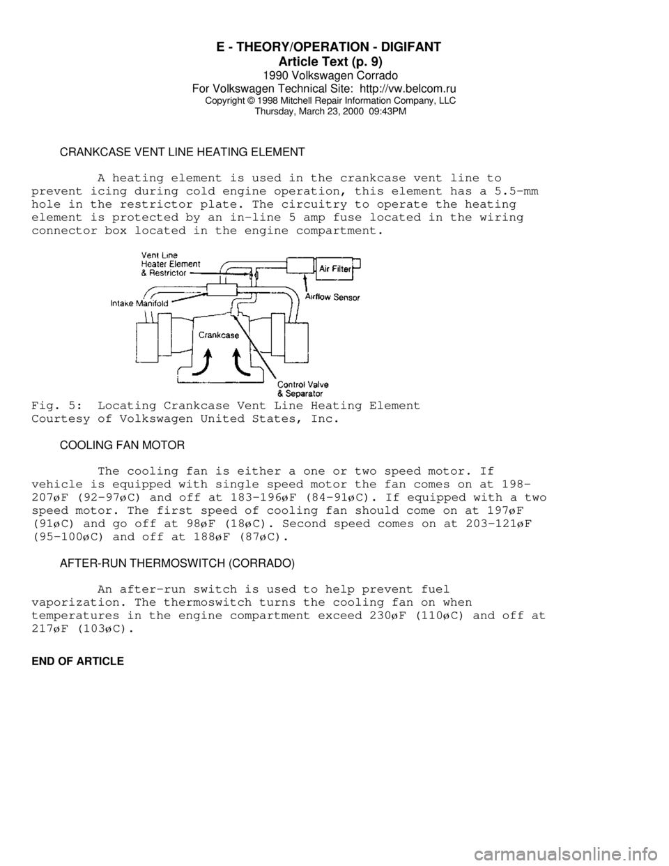
CRANKCASE VENT LINE HEATING ELEMENT
A heating element is used in the crankcase vent line to
prevent icing during cold engine operation, this element has a 5.5-mm
hole in the restrictor plate. The circuitry to operate the heating
element is protected by an in-line 5 amp fuse located in the wiring
connector box located in the engine compartment.Fig. 5: Locating Crankcase Vent Line Heating Element
Courtesy of Volkswagen United States, Inc.
COOLING FAN MOTOR
The cooling fan is either a one or two speed motor. If
vehicle is equipped with single speed motor the fan comes on at 198-
207øF (92-97øC) and off at 183-196øF (84-91øC). If equipped with a two
speed motor. The first speed of cooling fan should come on at 197
øF
(91
øC) and go off at 98øF (18øC). Second speed comes on at 203-121øF
(95-100
øC) and off at 188øF (87øC).
AFTER-RUN THERMOSWITCH (CORRADO)
An after-run switch is used to help prevent fuel
vaporization. The thermoswitch turns the cooling fan on when
temperatures in the engine compartment exceed 230
øF (110øC) and off at
217
øF (103øC).
END OF ARTICLE
Page 551 of 906

F - BASIC TESTING
Article Text (p. 6)
1990 Volkswagen Corrado
For Volkswagen Technical Site: http://vw.belcom.ru
Copyright © 1998 Mitchell Repair Information Company, LLC
Thursday, March 23, 2000 09:44PM
ALL EXCEPT CORRADO & VANAGON
1) Remove fuel return line located near left strut tower.
Remove fuel tank cap. Attach a piece of hose between return line and a
1 qt. (.95 liter) graduated container.
2) Activate fuel pump for 30 seconds by removing fuel pump
relay and attaching jumper wire between terminals No. 30 and No. 87.
Remove fuel pump relay from fuse/relay block. Compare volume with
specifications.
CORRADO
1) Disconnect wire harness connector from fuel pump. See
Fig. 4. With voltmeter attached to terminals, activate fuel pump by
removing fuel pump relay and applying battery voltage to terminals No.
4 of the fuse box connection for the fuel pump relay. Fuel pump relay
located on fuse box housing. Terminal numbers are molded into fuse box
plastic housing.
2) Record voltage. Remove fuel line from outlet side of
accumulator. See Fig. 4. Attach a piece of hose between return line
and a graduated container. Activate fuel pump for 30 seconds. Compare
volume with specifications given in MAIN FUEL PUMP VOLUME (AFC-
Digifant II) table.
VANAGON
1) Remove the return line from the pressure regulator located
in engine compartment left side. Push a piece of hose onto open
connection of pressure regulator. Insert hose into a 1 qt. (1 liter)
graduated container.
2) Activate fuel pump for 30 seconds by removing fuel pump
relay and attaching jumper wire between terminals No. 30 and No. 87.
Fuel pump relay located left side of engine compartment in Black
plastic box. Compare volume with specifications.
FUEL PUMP PERFORMANCE TABLE (AFC-DIGIFANT II)ÄÄÄÄÄÄÄÄÄÄÄÄÄÄÄÄÄÄÄÄÄÄÄÄÄÄÄÄÄÄÄÄÄÄÄÄÄÄÄÄÄÄÄÄÄÄÄÄÄÄÄÄÄÄÄÄÄÄÄÄÄÄÄÄÄÄÄÄÄÄ Pressure Min. Vol. in 30 Sec.
Application psi (kg/cm
ý) Pts. (L)
Cabriolet, Corrado,
Golf GL/GTI & Jetta .... 29-36 (2.0-2.5) ............... 1.0 (.5)
Vanagon ................. 33-39 (2.3-2.7) ............... 1.0 (.5)
ÄÄÄÄÄÄÄÄÄÄÄÄÄÄÄÄÄÄÄÄÄÄÄÄÄÄÄÄÄÄÄÄÄÄÄÄÄÄÄÄÄÄÄÄÄÄÄÄÄÄÄÄÄÄÄÄÄÄÄÄÄÄÄÄÄÄÄÄÄÄFUEL PUMP PERFORMANCE TABLE (CIS-E & CIS-MOTRONIC)
ÄÄÄÄÄÄÄÄÄÄÄÄÄÄÄÄÄÄÄÄÄÄÄÄÄÄÄÄÄÄÄÄÄÄÄÄÄÄÄÄÄÄÄÄÄÄÄÄÄÄÄÄÄÄÄÄÄÄÄÄApplication @ Voltage Min. Vol. in 30 Sec. Pts. (L)
Fox
10 ........................................... .8 (.375)
Page 555 of 906

F - BASIC TESTING
Article Text (p. 10)
1990 Volkswagen Corrado
For Volkswagen Technical Site: http://vw.belcom.ru
Copyright © 1998 Mitchell Repair Information Company, LLC
Thursday, March 23, 2000 09:44PM
distributor cap.ÄÄÄÄÄÄÄÄÄÄÄÄÄÄÄÄÄÄÄÄÄÄÄÄÄÄÄÄÄÄÄÄÄÄÄÄÄÄÄÄÄÄÄÄÄÄÄÄÄÄÄÄÄÄÄÄÄÄÄÄ HALL EFFECT SENDER & COIL POWER STAGE
The Hall Effect sender and coil power stage should be tested
if there is no spark at the spark plugs when tested. These tests also
check the CIS-Motronic ECU response to the Hall Effect sender signal.
Ensure SPARK and IGNITION COIL tests are performed first.
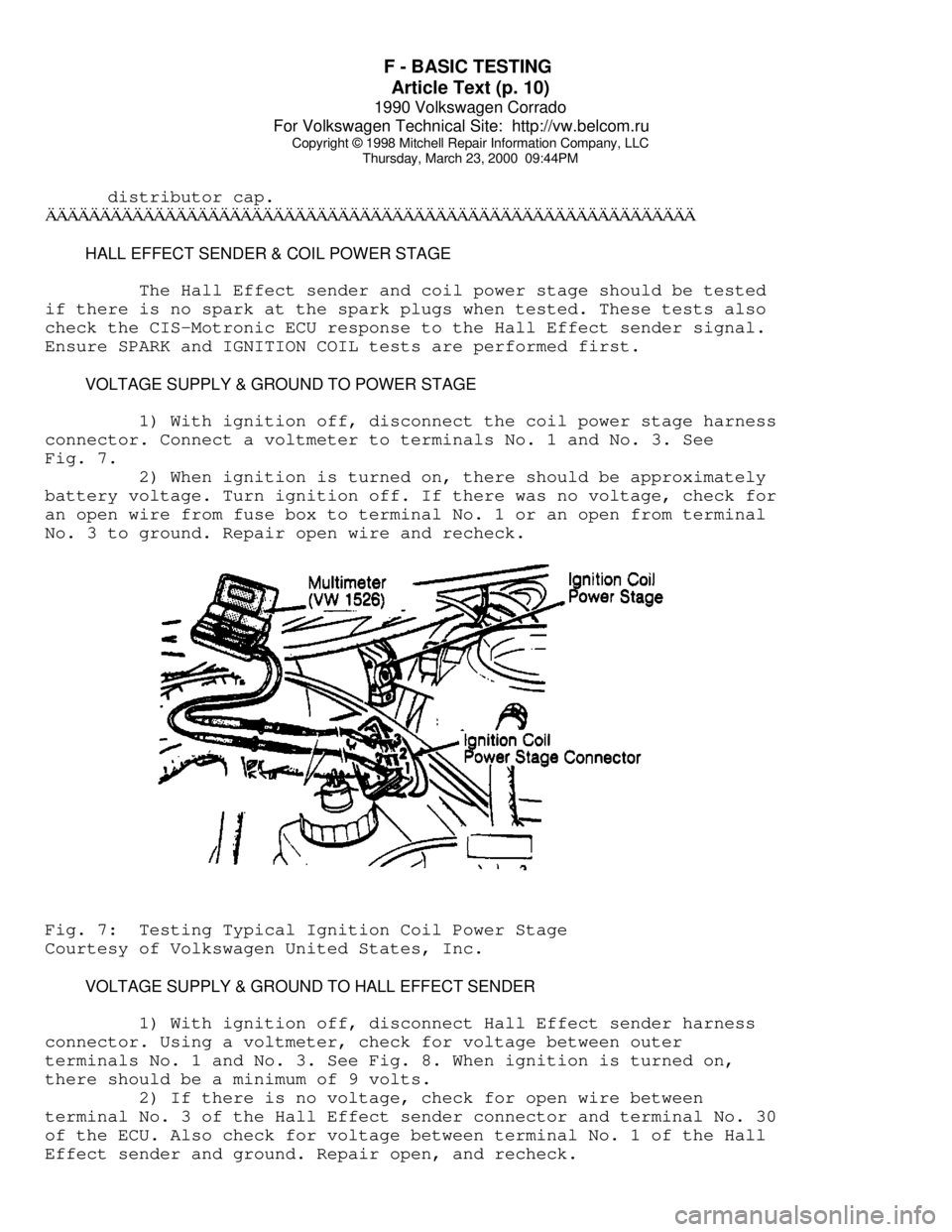
VOLTAGE SUPPLY & GROUND TO POWER STAGE
1) With ignition off, disconnect the coil power stage harness
connector. Connect a voltmeter to terminals No. 1 and No. 3. See
Fig. 7.
2) When ignition is turned on, there should be approximately
battery voltage. Turn ignition off. If there was no voltage, check for
an open wire from fuse box to terminal No. 1 or an open from terminal
No. 3 to ground. Repair open wire and recheck.Fig. 7: Testing Typical Ignition Coil Power Stage
Courtesy of Volkswagen United States, Inc.
VOLTAGE SUPPLY & GROUND TO HALL EFFECT SENDER
1) With ignition off, disconnect Hall Effect sender harness
connector. Using a voltmeter, check for voltage between outer
terminals No. 1 and No. 3. See Fig. 8. When ignition is turned on,
there should be a minimum of 9 volts.
2) If there is no voltage, check for open wire between
terminal No. 3 of the Hall Effect sender connector and terminal No. 30
of the ECU. Also check for voltage between terminal No. 1 of the Hall
Effect sender and ground. Repair open, and recheck.
Page 564 of 906

FUSES & CIRCUIT BREAKERS
Article Text (p. 2)
1990 Volkswagen Corrado
For Volkswagen Technical Site: http://vw.belcom.ru
Copyright © 1998 Mitchell Repair Information Company, LLC
Thursday, March 23, 2000 09:45PM
Right Tail & Side Lights
8 - 10 Amp
Left Tail & Side Lights
9 - 20 Amp
Rear Window & Mirror Heating
10 - 15 Amp
Foglights
11 - 10 Amp
Left High Beam, High Beam Indicator
12 - 10 Amp
Right High Beam
13 - 10 Amp
Horn, Radiator Fan
14 - 15 Amp
Back-Up Lights, Electric Mirrors, Heated Windshield Washer
Jets
15 - 10 Amp
Engine Electronic
16 - 15 Amp
Warning/Indicator Lights, Multi-Function Indicator, Glove Box
Light, Cassette Storage Light, Rear Spoiler
17 - 10 Amp
Turn Signals
18 - 20 Amp
Fuel Pump, Oxygen Sensor
19 - 30 Amp
Radiator Fan, Air Conditioner
20 - 10 Amp
Brakelights, Cruise Control
21 - 15 Amp
Dome & Luggage Compartment Lights, Cigarette Lighter, Central
Locking System, Multi-Function Indicator
22 - 10 Amp
Radio
CAUTIONS & WARNINGS
ELECTRICAL SHOCK
WARNING: Contact with live components of ignition system while
engine is running could lead to a fatal electric shock.
RADIATOR FAN
Keep hands away from radiator fan. Fan is controlled by a
thermostatic switch which may come on or run for up to 15 minutes even
after engine is turned off.
RADIATOR CAP
CAUTION: Always disconnect the fan motor when working near the
radiator fan. The fan is temperature controlled and could
Page 589 of 906

I - SYSTEM/COMPONENT TESTS
Article Text (p. 2)
1990 Volkswagen Corrado
For Volkswagen Technical Site: http://vw.belcom.ru
Copyright © 1998 Mitchell Repair Information Company, LLC
Thursday, March 23, 2000 09:46PMÄÄÄÄÄÄÄÄÄÄÄÄÄÄÄÄÄÄÄÄÄÄÄÄÄÄÄÄÄÄÄÄÄÄÄÄÄÄÄÄÄÄÄÄÄÄÄÄÄÄÄÄÄÄÄÄÄÄÄÄÄÄÄÄÄÄÄÄÄÄ CONTROL UNIT (AFC-DIGIFANT II)
NOTE: Before checking ECU terminal voltages, check all terminals
and connections for looseness or presence of corrosion.
Repair as needed, before continuing.
GROUND CIRCUITS
Using Multimeter (US 1119), check resistance of ground
connections for ECU. Remove ECU connector. Check continuity to ground
on terminals No. 13 and 19. See L - WIRING DIAGRAMS for terminal
identification. Resistance should be zero ohms. If resistance is not
zero ohms, repair open or short in wiring.
POWER CIRCUITS
1) Turn ignition off. Disconnect ECU connector. Using a
voltmeter, turn ignition on and check for battery voltage between ECU
connector terminals No. 13 (negative) and No. 14 (positive). See L -
WIRING DIAGRAMS for terminal identification and wire colors. If
battery voltage is not present, repair wiring as required.
2) Check terminals No. 13 (negative) and No. 1 (positive) for
battery voltage. If battery voltage is not present, check fuse No. 18
on fuse block. If fuse is okay, check wiring from ECU connector to
fuse box for open.
CONTROL UNIT (CIS-E)
GROUND CIRCUITS
Using Multimeter (US 1119), check resistance of ground
circuits for ECU. Remove ECU connector. Check continuity to ground on
terminals No. 2 and No. 9. Resistance should be zero ohms. If
resistance is not zero ohms, repair open or short in wiring.
POWER CIRCUITS
Turn ignition off. Disconnect ECU connector. Using a
voltmeter, turn ignition on and check for battery voltage between ECU
connector terminals No. 2 (negative) and No. 1 (positive). See L -
WIRING DIAGRAMS for terminal identification and wire colors. If
battery voltage is not present, check fuse No. 23 on fuse block. If
fuse is okay, check CIS-E ECU connector to fuse box wiring for open.
CONTROL UNIT (CIS-MOTRONIC)
GROUND CIRCUITS
Using Multimeter (US 1119), check resistance of ground
Page 590 of 906

I - SYSTEM/COMPONENT TESTS
Article Text (p. 3)
1990 Volkswagen Corrado
For Volkswagen Technical Site: http://vw.belcom.ru
Copyright © 1998 Mitchell Repair Information Company, LLC
Thursday, March 23, 2000 09:46PM
circuits to ECU. The ECU engine ground is near ignition distributor.
Remove ECU connector. Check resistance to ground on terminal No. 35.
Resistance should be zero ohms. If resistance is not zero ohms, repair
open or short in wiring.
POWER CIRCUITS
Turn ignition off. Disconnect ECU connector. Using a
voltmeter, check terminals No. 12, 14, 19 and 34 for battery voltage.
If battery voltage is not present. Check fuses No. 15, 18 and 24. If
fuses are okay, check for open in wiring between ECU and fuse box. See
L - WIRING DIAGRAMS for terminal identification and wire colors.
ENGINE SENSORS & SWITCHES
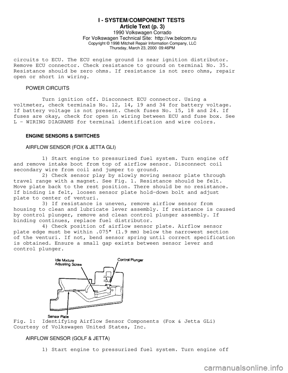
AIRFLOW SENSOR (FOX & JETTA GLI)
1) Start engine to pressurized fuel system. Turn engine off
and remove intake boot from top of airflow sensor. Disconnect coil
secondary wire from coil and jumper to ground.
2) Check sensor play by slowly moving sensor plate through
travel range with a magnet. See Fig. 1. Resistance should be felt.
Move plate back to the rest position. There should be no resistance.
If binding is felt, loosen sensor plate hold-down bolt and adjust
plate to center of venturi.
3) If resistance is uneven, remove airflow sensor from
housing to clean and lubricate lever assembly. If resistance is caused
by control plunger, remove and clean control plunger assembly. If
binding continues, replace fuel distributor.
4) Check position of airflow sensor plate. Airflow sensor
plate edge must be within .075" (1.9 mm) below the narrowest section
of the venturi. If not, bend sensor spring until correct specification
is obtained. Ensure a small gap exists between sensor lever and
control plunger.Fig. 1: Identifying Airflow Sensor Components (Fox & Jetta GLi)
Courtesy of Volkswagen United States, Inc.
AIRFLOW SENSOR (GOLF & JETTA)
1) Start engine to pressurized fuel system. Turn engine off