Page 263 of 391

AUTOMATIC TRANSAXLE - Transaxle Mechanism
PARKING MECHANISM
rking sprag (Annulus gear)Detent plateWanual control shaft)
Detent ball
17ooo7When the shift is in the “P” range, the parking pawl
paw1 cannot be moved upward, and the cam, while
engages with the parking sprag provided on outerpressing the spring, collides with the parking
paw1circumference of the
annulus gear to fasten theand the suppon, and is withheld in this condition. If
output shaft, preventing wheels from rotating. Inthe vehicle is moved even slightly in this condition,
other words, when the selector lever is set to thethe turning of wheels causes the
annulus gear to
“P” range, the detent plate and the parking spragturn as well. Since the cam is pressed in the
rod move in the direction of arrow, causing the camdirection of arrow, the parking pawl is pushed up as
on the parking sprag rod to push up the parking paw1a bottom of the sprag aligns with the parking sprag
to engage with the sprag.to engage with the sprag.
In case the parking paw1 collides against a crest of
the sprag, only the rod moves because the parkingIn this way, the parking mechanism eliminates any
chances of the vehicle from being idly moved.
Page 264 of 391

21-40AUTOMATIC TRANSAXLE - Transaxle Mechanism
START SAFETY MECHANISM
Inhibitor switch
Manual control lever
--
Connector-7DN R
‘,T,i \ ! I
‘\FlI
\ L
,p
( /1750253
1750149
Internal Connection in the inhibitor Switch
,
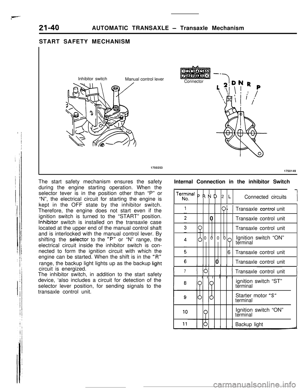
Teh;ina’ P R N D 2 LConnected circuits1 The start safety mechanism ensures the safety
during the engine starting operation. When the
selector tever is in the position other than “P” or
“N”, the electrical circuit for starting the engine is
kept in the OFF state by the inhibitor switch.
Therefore, the engine does not start even if the
ignition switch is turned to the “START” position.Inhibitor switch is installed on the transaxle case
located at the upper end of the manual control shaft
and is interlocked with the manual control lever. By
shifting the selector to the
“P” or “N” range, the
electrical circuit inside the inhibitor switch is con-
nected to form the ignition circuit with which the
engine can be started. When the shift is in the
“R”range, the backup light lights up as the backup
lightcircuit is energized.
The inhibitor switch, in addition to the start safety
device, ‘also includes a circuit for detection of the
selector lever position, for sending signals to the
transaxle control unit.
011Transaxle control unit0
Transaxle control unit
Transaxle control unit0000Ignition switch “ON”
terminal6
Transaxle control unit0
Transaxle control unit
I
7) 161 ) 1 ( 1Transaxle control unit
I I I I I I IIignition switch “ST”
terminalStarter motor “S”
terminal
10Ignition switch “ON”terminal
Backup light
Page 266 of 391

21-42AUTOMATIC TRANSAXLE - Transaxle Control
ELECTRONIC CONTROL DEVICE
DAMPER CLUTCH CONTROL
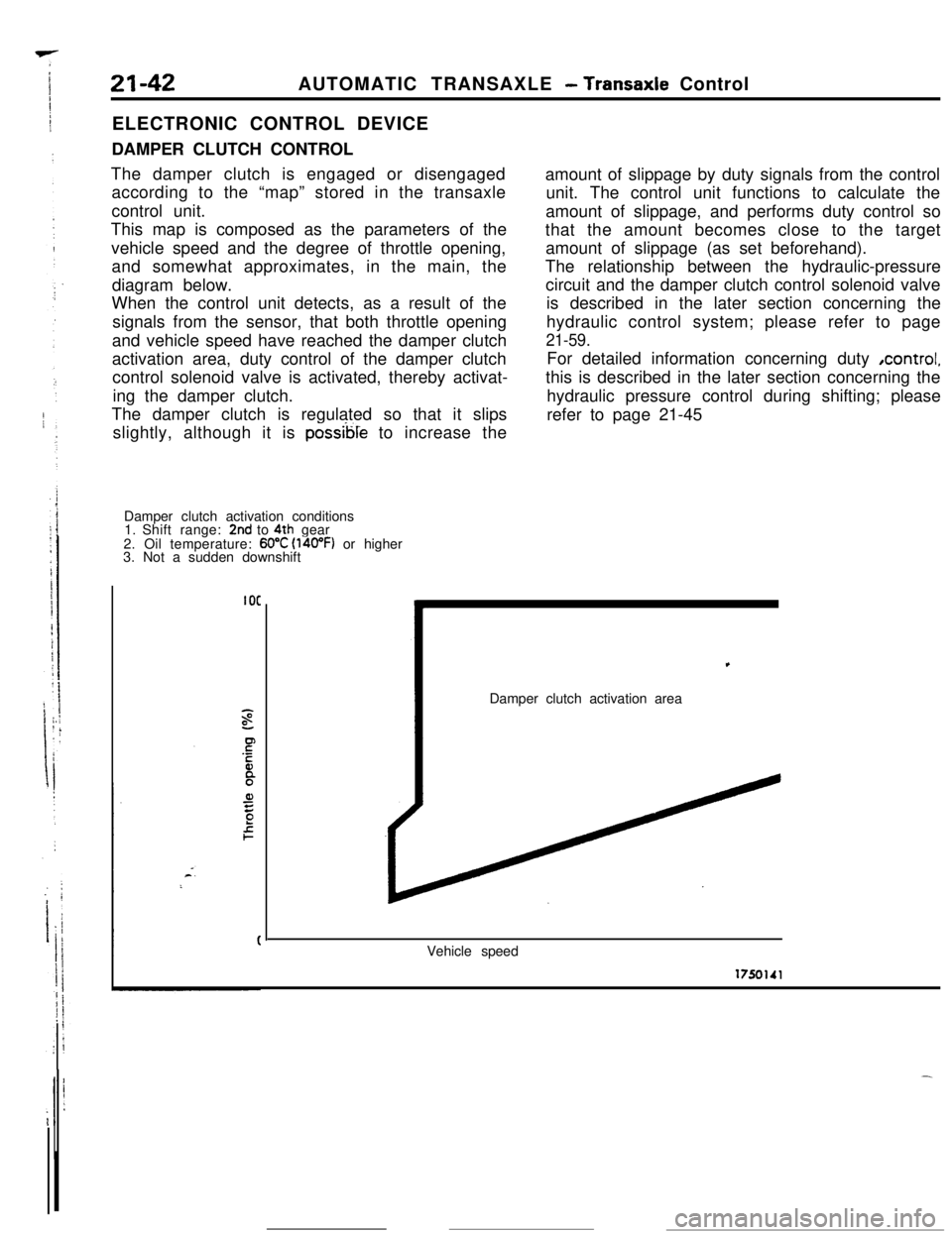
The damper clutch is engaged or disengaged
according to the “map” stored in the transaxle
control unit.
This map is composed as the parameters of the
vehicle speed and the degree of throttle opening,
and somewhat approximates, in the main, the
diagram below.
When the control unit detects, as a result of the
signals from the sensor, that both throttle opening
and vehicle speed have reached the damper clutch
activation area, duty control of the damper clutch
control solenoid valve is activated, thereby activat-
ing the damper clutch.
The damper clutch is regulated so that it slips
slightly, although it is
possible to increase the
Damper clutch activation conditions
1. Shift range:
2nd to 4th gear
2. Oil temperature: 60°C (l4oOF) or higher
3. Not a sudden downshift
IOCamount of slippage by duty signals from the control
unit. The control unit functions to calculate the
amount of slippage, and performs duty control so
that the amount becomes close to the target
amount of slippage (as set beforehand).
The relationship between the hydraulic-pressure
circuit and the damper clutch control solenoid valve
is described in the later section concerning the
hydraulic control system; please refer to page
21-59.For detailed information concerning duty ,control,
this is described in the later section concerning the
hydraulic pressure control during shifting; please
refer to page 21-45,
Damper clutch activation area
Vehicle speed
Page 273 of 391

.-AUTOMATIC TRANSAXLE
- Transaxle Control21-49
Transaxlecontrol unit
Eel
6017!au72
THROmE POSITION SENSOR
The throttle position
SenSOr is installed on the throttle body.
The throttle position sensor Of variable resistor type
senses thethrottle valve
opening.
As the throttle shaft turns, the resistance i.e. output voltage of
throttle position sensor changes. This throttle position sensor
output voltage is input to the transaxle control unit to compute
the throttle opening.
The throttle position sensor output voltage can be adjusted by
turning the throttle position sensor body.
Throttle position sensor output characteristics
5
1
0’ ’10 20 30 40 50 60 70 80 82Totally Throttle valve opening (degrees) Totally
closedopened7FUO75control switchKICKDOWN SERVO SWITCH
The adjust sleeve and the retainer constitute the contacts of
the kickdown servo switch. The switch detects the position of
the kickdown piston just before the kickdown brake is applied,
and sends the signal to the transaxle control unit.
When the kickdown servo is not in operation, the switch
contacts are kept closed.
When the hydraulic pressure is applied to the kickdown servo
and the piston is operated,
the’adjust sleeve separates from
the retainer, turning off the. switch.
Using the kickdown servo switch OFF signal as its standard,
thetransaxle control unit controls the 2nd pressure before, and
during application of the brake by actuating the pressure
control solenoid valve.
OVERDRIVE CONTROL SWITCH
When the overdrive control switch is ON, operation is as a
O-speed automatic transaxle.
When the overdrive control switch is OFF, the indicator light
(within the combination meter) is illuminated, and operation
isas a
3-speed automatic transaxle.
Page 300 of 391
21-78AUTOMATIC TRANSAXLE - Transaxle Control
N-D CONTROL VALVE
.-.‘r
To rear clutch viarear clutch exhaust valve
N-Dcontrol
valve
EXpressure
Pressurecontrol
valve
t
Reducingpressure
t
Red”&pressure
175oz39
The purpose of this valve is to prevent shock from
occurring when shifting the select lever from “N” to
“D”. The valve supplies the rear clutch with the oilpressure regulated by the pressure control valve
only when the N-D shifting is being performed. After
the shifting is completed, the valve is switched over
to allow the line pressure to be supplied to the rear
clutch.
Selector Lever in ‘N”
When the manual valve is shifted to the “N” rangeposition, the line pressure from the oil pump is
directed to the N-D control valve through the No.4line. As the
#2 land has a slightly larger area to
which pressure is applied than that of the #3 land of
the N-D control valve, the movement of the valve
caused by the line pressure is toward the left, whichcloses the
No.5 port.
Page 336 of 391
i73BODY
- Doors23-19The doors are front hinged, sash doors opening
Lowards the rear with the following features.
lThe sash is flush with the body and has had its
height difference with the glass
surface mini-
mized to reduce wind noise.
* By effectively employing reinforcements, the
regularorrigidity of the outer panels and the rigidity of thebeltline openings have been improved.
lA two-step door check has been adopted to hold
the door securely at the midway position.
l The window regulator is of a compact and
light-weight wire winding type.
Door beltline innerreinforcement
Door beltline outer
reinforcement
Door lower
hinr-reinforcement *-lentDoor side impact bar
l6A0463
16AO462Door lower hinge
Page 337 of 391

23-20BODY - Central Door LocksCENTRAL DOOR LOCKS
Ri... 4sThe central door-lock system, by which all doors can
be locked or unlocked (from the inside by using the
inside door lock knob at either front door, or from
the outside by using the door key), not only sewes
to reduce the trouble of individually locking orunlocking each door when passengers get out or
get in, but also maintains passenger safety.
For the central door-lock system, the operation of
the lock actuator is regulated by the door control
unit.
Door lock actuator(right side)Door-control unit
(left side)
Door lockcontrol relay16A0464
PTC heater
/MotorISwitchDOOR LOCK ACTUATOR
The actuator is light in weight and is the highly reliable motor
We.
NOTE
The door lock actuator incorporates an internal PTC thermist’-so as to Prevent damage as the result of overheating of
L
motor.*: PTC
is an acronym for Positive Temperature Coefficient.
The thermistor with a positive temperature coefficient
ofresistance provides more resistance as it generates
heat,thus limiting current and controlling the amount of
haat
generated.
Page 341 of 391

23-24BODY - Power Windows / Bumpers
Batterv
r--+----
02’
BUMPERSA large-size integral soft fascia is installed both for
the front and rear bumpers, which prevents perma-
nent deformation in light collision.
The bumpers feature the highly rigid bumper
rein-
18A0420
Section A-A
Front turn Front bumper
/Front bumperbumper
t Jabsorber
reinforcement18AOllB
1. After the delay time (0.7 second) has
claps,+,,,the voltage (comparison voltage) at the negative
(-1 side of IC2 becomes higher than the refer-
ence voltage at the positive
(+) side, with the
result that the output voltage of
ICI becomes
low, and the transistor
(Tr) is switched OFF.
2. As a result of the transistor
(Tr) being switched
OFF, current stops flowing to the coil
(L), and
thus there is no longer the force to hold the
plunger.
3.As a result, the switch is returned to the neutral
status by the return spring, and the motor
operation stops.
R22JMBforcement, shock absorber, and highly rigid
b --
frame, all of which contributes to the reduL.
aprotrusion, yet ensuring
5-mph bumper perform-
ance for the enhanced safety.
Rear bumpe:,.AOIOI
-