1990 MITSUBISHI ECLIPSE low oil pressure
[x] Cancel search: low oil pressurePage 221 of 391

POWER STEERING - Oil Pump
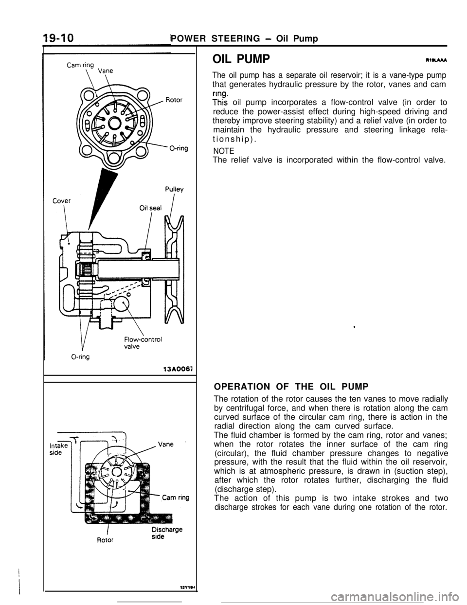
OIL PUMP13A0067
Insi
m-
The oil pump has a separate oil reservoir; it is a vane-type pumpthat generates hydraulic pressure by the rotor, vanes and cam
;Inhz oil pump incorporates a flow-control valve (in order to
reduce the power-assist effect during high-speed driving and
thereby improve steering stability) and a relief valve (in order to
maintain the hydraulic pressure and steering linkage rela-
tionship).
NOTEThe relief valve is incorporated within the flow-control valve.
.OPERATION OF THE OIL PUMP
The rotation of the rotor causes the ten vanes to move radially
by centrifugal force, and when there is rotation along the cam
curved surface of the circular cam ring, there is action in the
radial direction along the cam curved surface.
The fluid chamber is formed by the cam ring, rotor and vanes;
when the rotor rotates the inner surface of the cam ring
(circular), the fluid chamber pressure changes to negative
pressure, with the result that the fluid within the oil reservoir,
which is at atmospheric pressure, is drawn in (suction step),
after which the rotor rotates further, discharging the fluid
(discharge step).
The action of this pump is two intake strokes and two
discharge strokes for each vane during one rotation of the rotor.
Page 222 of 391

POWER STEERING - Oil Pump
PERFORMANCE OF THE OIL PUMP
(1)
19-11 i
P-Qf characteristic (pump pressure vs. discharge quantity)
At pump rotation of 600 rpm and fluid temperature of
50-6O”C (122-l 40°F):4.4
litmin. (268.5 cu.in./min.), or more at pump pressure of
4,000
kPa (569 psi)
N-Qf Characteristic (pump rpm vs. discharge quantity)
At pump pressureof 2,000
kPa (285 psi) and fluid
temperature of
50-60X (122-140°F):
6.58
lit./min. (396.7-488.2 cu.in./min.) at pump rotation of
1,500 rpm.
3.8-6 lit./min. (231.9-366.1 cu.in./min.) at pump rotation of
3,000 rpm.
2.5-3.5 Mnin. (152.6-213.6 cu.in./min.) at pump rotation
of 4,500 rpm.
OPERATION OF THE FLUID
FLOW-
r7NTROL SYSTEM
I t 13 plunger and flow-control valve are activated bythe oil pump, thus regulating the amount of fluid
the hydraulic pressure of the fluid discharged fromflow to the gear box.
Pl;lgRelief ipring\
Relief valve13POO37
Page 223 of 391

19-12POWER STEERING - Oil Pump
WHEN OIL PUMP OPERATES AT LOW SPEED
(70&l ,000 RPM)
A part of the fluid discharged from the oil pumpvariable orifices. As a result of this action the fluid
passes through the pilot port and hydraulic pressurepasses through the variable and fixed orifices, and is
is applied to the rear surface of the plunger, but,sent, by way of the plunger, to the gear box. The
because this hydraulic pressure is weak, the plungeramount of discharge to the gear box at this time is
is pushed toward the left as a result of the forcealmost maximum, with the result that an extremely
applied by the plunger’s spring, thus opening thelow steering effort is required.
PlungerVariable orificeFixed,orificeFioycontrol valve
/ I
From oil pump
To oil pumpVariable orifice
13POO38-.
Pilot portFixed orifice
.WHEN OIL PUMP OPERATES AT MEDIUM
SPEED
(1 ,OOm,OOO RPM)
When the engine speed increases and the pump’ssame time, the flow-control valve also is pressed
speed also increases, the hydraulic pressure of thetoward the
right, the bypass port opens more, and
fluid discharged from the pump becomes higher,the surplus fluid is returned back to the oil pump. In
overcoming the plunger spring’s force, and causingthis way, the amount of discharge flow to the gear
the plunger to move toward the right. As a result ofbox is reduced, thus resulting in a somewhat
this action, one of the variable orifices closes. At the“heavier” steering effort.
Variable orifice
PlungerFlow-control valve
\\Fixed yrifice/
Variable &iflceBypass ‘LrllJPOO59
Page 224 of 391

i t-7POWER STEERING
- Oil Pump19-13WHEN OIL PUMP OPERATES AT HIGH SPEED
(? -70 RPM OR MORE)
VII, ,dn the pump operation becomes high speed. thethe gear box then is supplied only from the fixed
plunger is pushed further toward the
right than fororifice, with the result that the amount of discharge
medium speed, and both variable orifices close.flow
is reduced to minimum, and, as a result, theFurthermore. the flow-control valve also moves, and
steering effort becomes moderately “heavy”, thus
the bypass port opens wider. The fluid flowing to
providing excellent handling stability at high speed.
Fixed orifice13POO40
OPERATION OF THE RELIEF VALVE
When the A chamber pressure increases when theAs a result of this action, the pressure of the
Bsteering wheel is turned while the vehicle ischamber decreases, and the relief valve closes once
stopped, the
B chamber pressure also increases.again. This action takes place in a moment, and in
and, when the pressure exceeds the relief springthis way, by maintaining the correct balance, the
set load of 8,000 kPa (1,138 psi), the relief valve panmaximum pressure is controlled.
which is closed by a steel ball opens and the fluid
passes through the bypass port and is returned to
the pump’s intake port.
Steel ballRelief sprtngTo steering gear box
/Bypass pan
WPOO41
Page 240 of 391

_-
21-16AUTOMATIC TRANSAXLE - General InformationAUTOMATIC
TRANSAXLE
GENERAL INFQRMATIONRzlBBACF4A22 automatic transaxles with different shift pattern are introduced to match engine output characteristics.
These F4A22 automatic transaxles are transaxles of KM1 70 Type II series and each is a two-mode
electronically controlled automatic transaxle with shift patterns of two modes.
SPECIFICATIONS
Items
Transaxle modelTorque convertor
Me
Stall torque ratio
TransaxleType
Gear ratio
1 St
2nd
3rd4th
ReversePrimary reduction ratio
Differential gear ratio
Friction elements
Number of front clutch discs
Number of rear clutch discs
Number of end clutch discs
Number of low/reverse brake discs
Number of
kickdown brake bandControl system
Manual control system
Shift pattern type
Solenoid yalve operationShift control
(2)
Pressure control
Damper clutch controlDiagnosis
Indication method
Number of diagnosis items
Speedometer gear ratio
ATFOil quantityliter
(qts.)
Specifications-4A22-2-MPAl3element, 1 -stage,
2-phase with damper clutch
2.17l-speed forward, l-speed reverse
2.846
1.581
1
.ooo
3.685
2.176
1.125
3.611V&N-D-2-L (lever type) with overdrive switch
Two-mode electronic-hydraulic control type
ON-OFF controlDuty control
Duty control
Indication with
LEDs
24
29136
MOPAR ATF PLUS (AUTOMATIC TRANSMISSIOI
FLUID TYPE 7176VAutomatic Transmission Fluid“DEXRON” or “DEXRON II”
\I6.1
(6.4)J
Page 246 of 391

AUTOMATIC TRANSAXLE - Torque Converter
TORQUE CONVERTER
Lock
ring
I
Damper
F
clutch-
B-.Turbine
.AA
/:ront cover
h,Impeller
AStartorWhen damper clutch is
I\When damper
aInput shaftactivated
clutch isactivated
175202The torque-converter is composed of the impeller
(rear cover), turbine,
stator, damper clutch, one-way
clutch, front cover, etc.Furthermore. the torque-converter cannot be dis-
assembled because the outer circumference of the
shell
(front cover and rear cover) is sealed by
welding.
Because the torque-converter is coupled to the
engine’s crankshaft (via the drive plate). the shell
(front cover and impeller) always turns in the same
way when the engine is running.
As a result, the oil pump is also caused to rotate (by
the hub welded to the center part of the rear of the
shell) at the same speed as the engine.
The boss at the front part of the shell is inserted in
the hole at the rear part of the crankshaft. thus
providing support of the torque-converter.
A facing like that attached to the transaxle’s clutch
disc is attached to the damper clutch, and the
damper clutch and the turbine are connected by the
tabs (of the lock ring on the outer circumference of
the turbine shell) that fit into the groove on the outer
circumference of the damper clutch.
The torque-converter actuation hydraulic pressure,at the damper clutch activation area, passes be-
tween the torque-converter’s hub and the reaction
shaft, and enters the torque-converter.
When this happens, the hydraulic pressure acts
upon the A part (between the damper clutch and the
turbine), with the result that the damper clutch is
pressed against the front cover, and the damper
clutch, with a slight slip (as described later) becom-
es connected.
In this manner, the amount of slippage of the
torque-convener is reduced, without a damper
spring, to far below at even the low-speed level,
thus making a practical improvement of fuel con-
sumption.
At the damper clutch non-activation area, because
the torque-converter actuation hydraulic pressure
passes through the input shaft oil passage
-1enters the torque-converter from the
B part &-tween the damper clutch and the front cover). the
damper clutch moves away from the front
cover,thus releasing the damper clutch.
In this condition, operation is as an ordinary torque-
converter.
Page 250 of 391

21-26AUTOMATIC TRANSAXLE - Transaxle Mechanism
REAR CLUTCH
Wave sprmgRear clutch retainer
Clutch reaction piateClutch pressure plate
I1rao2l5Rear clutch is of the multiple disc type, and is
composed of a rear clutch retainer, disc, plates, and
a piston. When the piston is actuated by the oil
pressure, the multiple disc clutch is connected,
conveying driving force from the input shaft to the
forward sun gear in the planetary gear set. The rear
clutch is always actuated when the shift is in first,
second and third gears.
INumber of clutch discsI.3I
1 Number of clutch piates1 2 I-
I Number of reaction plates
I
1 1
I Number of pressure plates’I 1 I
PistonO.D.mm (in.)121 (4.761
I.D.mm (in.)36 (1.42)
POWER FLOW
Rear clutch
Rear clutch hubRear clutch retainer
Forward sun gear,
IInput shaftRear clutch retainerRear clutchRear clutch hubForward sun gear
Page 266 of 391

21-42AUTOMATIC TRANSAXLE - Transaxle Control
ELECTRONIC CONTROL DEVICE
DAMPER CLUTCH CONTROL
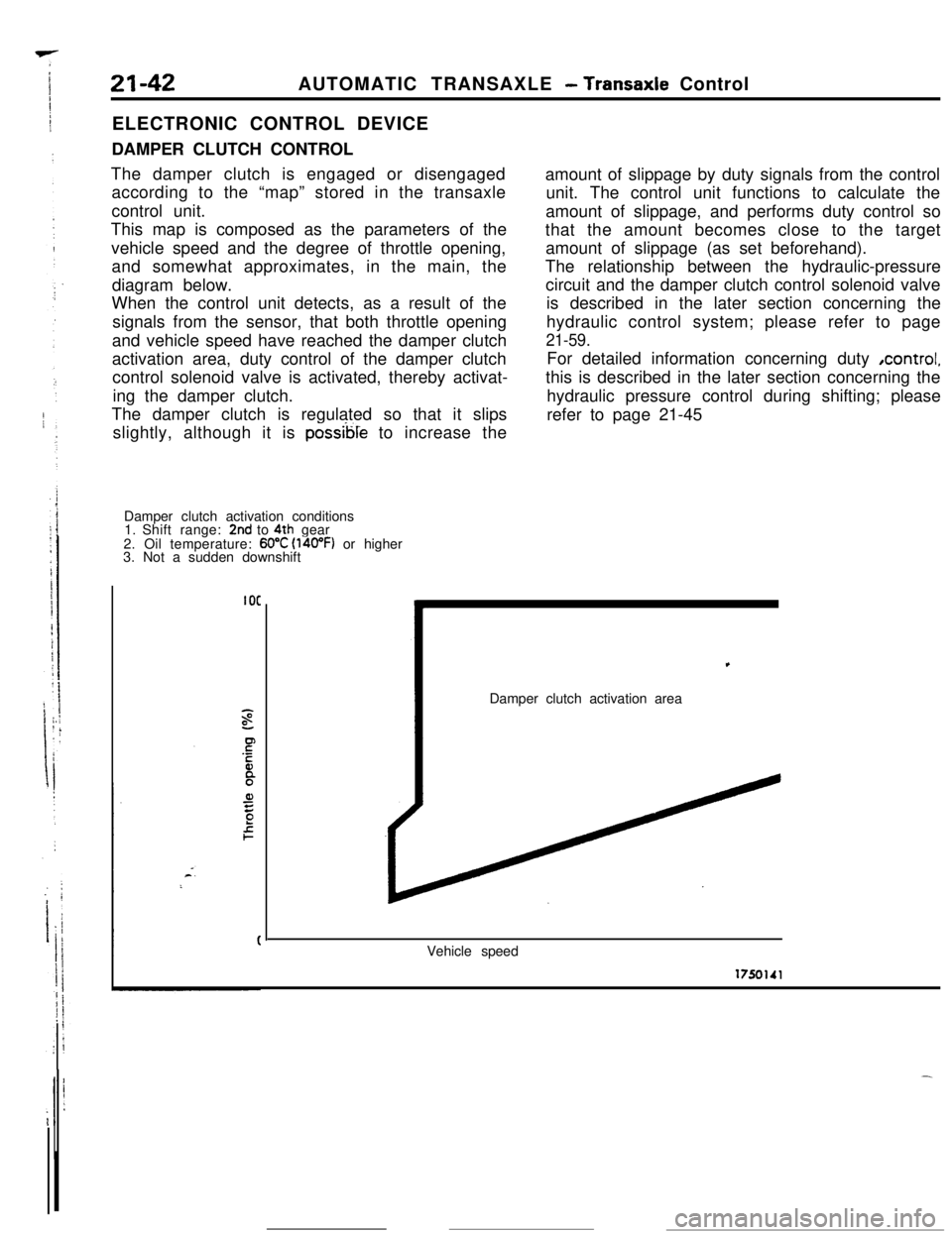
The damper clutch is engaged or disengaged
according to the “map” stored in the transaxle
control unit.
This map is composed as the parameters of the
vehicle speed and the degree of throttle opening,
and somewhat approximates, in the main, the
diagram below.
When the control unit detects, as a result of the
signals from the sensor, that both throttle opening
and vehicle speed have reached the damper clutch
activation area, duty control of the damper clutch
control solenoid valve is activated, thereby activat-
ing the damper clutch.
The damper clutch is regulated so that it slips
slightly, although it is
possible to increase the
Damper clutch activation conditions
1. Shift range:
2nd to 4th gear
2. Oil temperature: 60°C (l4oOF) or higher
3. Not a sudden downshift
IOCamount of slippage by duty signals from the control
unit. The control unit functions to calculate the
amount of slippage, and performs duty control so
that the amount becomes close to the target
amount of slippage (as set beforehand).
The relationship between the hydraulic-pressure
circuit and the damper clutch control solenoid valve
is described in the later section concerning the
hydraulic control system; please refer to page
21-59.For detailed information concerning duty ,control,
this is described in the later section concerning the
hydraulic pressure control during shifting; please
refer to page 21-45,
Damper clutch activation area
Vehicle speed