Page 106 of 677

OUTLINE Fl
OlJTLlNE OF CONSTRUCTION
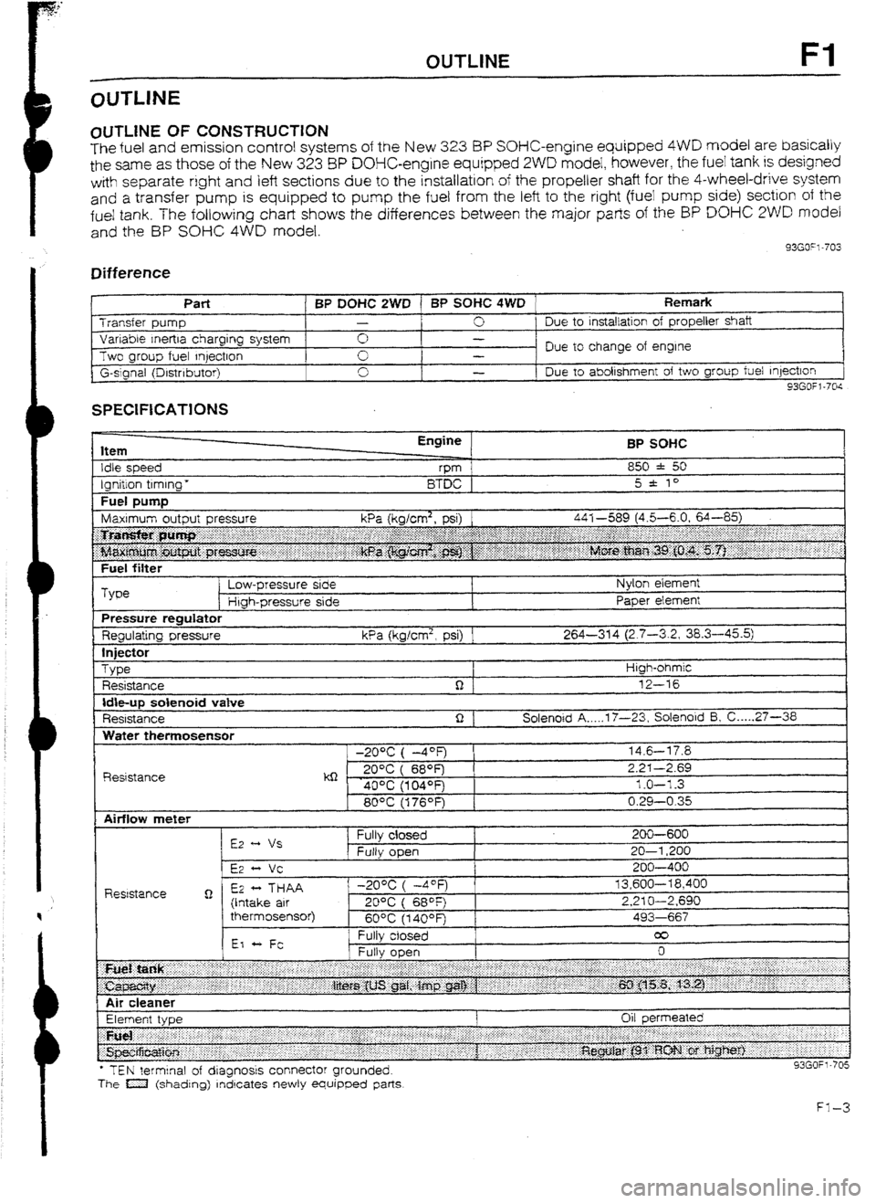
The fuel and emission control systems of the New 3.23 BP SOHC-engine equipped 4WD model are basically
the same as those of the New 323 8P DOHC-engine equipped 2WD model, however, the fuel tank is designed
with separate right
and left sections due to the installation of the propeller shaft for the 4-wheel-drive system
and
a transfer pump is equipped to pump the fuel from the left to the right (fuei pump side) section of the
fue! tank. The following chart shows the differences between the major parts of the BP DO% 2WD model
and the BP SOHC 4WD model.
33GO”l-703
Difference
I t
Part BP DOHC 2WD 1 BP SOHC 4WD Remark Transfer pump -
0 Due to
installation of propeller shaft
Variable Inertra charging system 0 -
Two group fuel qectron Due to change of engine
-
G-slgnal (Drstnbutor) 0
I -
Due to abolishment of two group fuel Injection
93GOfl-70s
SPECIFICATIONS
Item
Idle speed
Ignition timing * Engine
vm
BTDC BP SOHC
850 * 50
5 * to
Fuel DUtTlD I
Fuel filter
Type Low-pressure side
Htgh-pressure side Nylon element
Paper element
Pressure regulator
Regulating pressure kPa (kglcm2, psi) 1 264-314 (2.7-3.2, 38.3-45.5)
In
jfXt0r
Type
Resistance High-ohmic
12-16
Idbup solenoid vatve
Resistance Solenoid A _.._. 17-23, Solenoid 5, C ._... 27-36
Water themosensor
R&stance -20% ( -4OF)
kQ - . 20°C ( 689=)
40% (104OFj
80°C (176OF) 14.6-l 7.8
2.2-I -2.69
1.0-l -3
0.29-0.35
l TEN terminal of dragnosrs connector grounded.
The a (shading) rndrcates newly equipped parts
Page 121 of 677

F2 OUTUNE
OUTLINE OF CONSTRUCTION
The fuel and emission control system of the new 323 4WD model is basically the same as that of the new
323 2WD modet; however, a turbocharger and knock control system are added to the BP TURBO model
and the fuel tank is designed
with separate right and left sections due to the installation of the propeller shaft
for the 4-wheel-drive system. A transfer pump is also equipped to pump the fuel from the left
to the right
(fuel pump side) section of the fuel tank.
The major points of difference between the 2WD model and 4WD model are as shown below.
93GOF2-705
Difference
Component 2WD 4WD
BP SUHC BP OOHC BP SOHC BP TURBU Remark
INTAKE AG! 1 Resonance duct 0 0 0 - -
SYSTEM
Resonance chamber 0
0 G -
VICS .-
ui- - -
Turbocharger - - -
0 Refer to page
FZ-12
I ntercooler - - -
0 Refer to page FZ-14
Air bypass valve - - -
0 Refer to page F2-14
FUEL SYSTEM Fuel pump control - - -
0 Refer to page F2-16
Transfer pump - -
0 0 Refer to page F2-18
Operating time for BP
Pressure regulator control 0 0 0 0
TURBO is different
(Refer to page F2-23)
Fuel pump reststorlrelay - - -
0 Refer to page F2-18
EVAPORATIVE
EMISSION
Fuel vapor vatve - -
CONTROL 0 0 Refer to page F2-16
SYSTEM
CONTROL
SYSTEM Point type
0 0
Throttle sensor 0 (MTX) -
-
Variable type - -
0 W-x) 0
Without heater
0 0 0 -
Oxygen sensor F
With heater - -
- 0 Refer to page F2-23
Water thermoswitch (on radiator)
-
Knock control system -
Overboost wami ng buzzer -
Turbocharge Indicator - -
C @TX) - NC cut-off system
- - 0
Refer to page F2-22
- -
0 Refer to page F2-21
- - 0 Refer to page F2-21
93GOF2-706
Page 132 of 677
FUEL SYSTEM F2
FUEL SYSTEM
Due to the installation of the propeller shaft fur the 4WD, the fuel tank is designed with left and right section.
Therefore, a transfer pump is used to pump the fuet from the left to the right (fuel pump) side. The transfer
pump is mounted in the fuel tank, and is controlled by the transfer pump switch and the fuel pump control unit.
The fuel pump control system is adopted for BP turbo model.
CONSTRUCTION
PRESSURE REGULATOR
FUEL PUMP
FUEL PUMP
RESISTOR/REU\Y
TRANSFER PUMP
/
FUELPUM IP SWI’
TCH
FUEL VAPOR
FUEL TANK
i
4x4 CONTROL UNIT [BP SOHC]
FUEL PUMP CONTROL UNlT [BP TURBO]
Page 190 of 677

OUTLINE G
L
i i-
OUTLINE
OUTLINE OF CONSTRUCTION
The engine electrical system of the new 323 4WD is as same as that of the new 323 ZWD.
93GOGX-703
SPECIFICATIONS
Item
Battery t
Voltaae EnginelTransaxle
v
Type and capacity
120-hour rate) BP TURBO
MTX BP SOHC
MTX ATX 12
55D23L (60AH)
I
Dark current” mA 1 Max. 20.0
Alternator
Output V-A 12-65
Regulator type Transistorized (built-in iC regulator)
1 I Regulated voltage v
74.1---14.7
Brush length Standard 21.5 (0.846)
mm (in)
Minrmum 8.0 (0.315)
Drive belt deflection
New
98 N (10 kg, 22 lb) 8-9 (0.31-0.35)
mm (in) Used 9-l 0 (0.35-0.39)
Type Direct ] Coaxicat reductron Starter Output V-W
12-U-85 12-0.95 32-l .4
8rush length Standard 17 (0.67) 17.5 (0.69)
mm [in) Minimum 11.5 (0.4531 10.0 (0.39) Distributor
Ignition timing
BTDC
FEN termrnal of diagnosis connector grounded) Electronic spark advance (photo
diode)
10 * I0 5 f lo
Ignition coil Resistance
(at 20°C [68OFj)
I
Primary
coil windinq
I
Spark plug Type I
Secondary 1
f coil windina 1
NGK
Nippon
Denso 10-76 kS-l
8KR5Ell +2 BKR5E”3
BKRGEI 1 l * BKRGE *3
KIGPR-Ull *2 KfGPR-I-Y3
K20PR-Ul l ** K20PR-U
l 3 0.81 ---o-999
pw am
Firrng order
I mm (in) 1.0-I .l (0.039-0.043)“2 0.7-0.8 (0.028-0.03i)*3
l-3-4-2
93GOGX-704
*I Dark current is the constant flow of current while the ignition switch is OFF. (i.e., engine control unit, EC-AT control unit, audro, etc.)
+’ With catalytic converter.
*3 Without catalytic converter.
G-3