Page 17 of 30

INTRODUCTION AND MASTER TROUBLESHOOTING - Towing and Hoisting 17
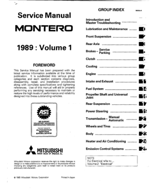
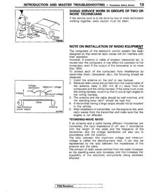
TOWING AND HOISTING
This vehicle can only be towed from the front with convention-
al sling-type equipment and tow chain with grab hooks.
If a vehicle is towed from the rear, use a tow dolly.
A lumber spacer (4” x 4” x 55” wood beam) should be placed
forward of under guard and under towing hook/shipping tie
down hook.
Then, attach J-hook to the lower arm.
A safety chain system must be used. This system must be
completely independent. of the primary lifting and towing
attachment. Care must be taken in the installation of safety
chains to insure they do not cause damage to bumper, painted
surfaces or lights.
LIFTING-GROUND CLEARANCE
Towed vehicle should be raised until wheels are a minimum of
10 cm (4 in.) from the ground. Be sure there is adequate
ground clearance at the opposite end of the vehicle, especially
when towing over rough terrain or when crossing sharp rises
such as curbs. If necessary, ground clearance can be in-
creased by removing the wheels from the lifted end of the
disabled vehicle and carrying the lifted end closer to the
ground. A 20 cm (8 in.) ground clearance must be maintained
between brake drums and ground.
FRONT TOWING PICKUP
The vehicle may be towed on its rear wheels for extended
distances, provided the parking brake is released.
Make cartain the transmission remains in “NEUTRAL”.
SAFETY PRECAUTIONS
The following precautions should be taken when towing the
vehicle.
1. Remove exhaust tips and any other optional equipment,
that interface with the towing sling. Padding (heavy shop
towel or carpeting) should be placed between the towing
sling cross bar and any painted surfaces, and bumper
surfaces.
2. A safety chain system completely independent of the
primary lifting and towing attachment must be used.
3. Any loose or protruding parts of damaged vehicle such as
hoods, doors, fenders, trim, etc., should be secured prior
to moving the vehicle.
4. Operator should refrain from going under a vehicle unless
the vehicle is adequately supported by safety stands.
5.
Never allow passengers to ride in a towed vehicle.
6. State and local rules and regulations must be followed
when towing a vehicle.
1 TSB Revision
Page 18 of 30

.$i ~[ r
18 INTRODUCTION AND MASTER TROUBLESHOOTING - Towing and Hoisting
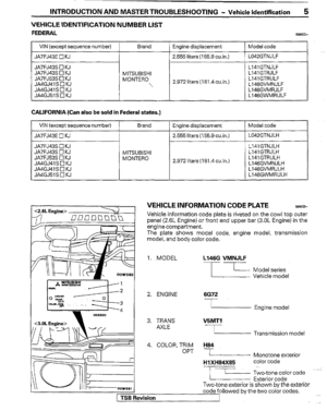
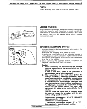
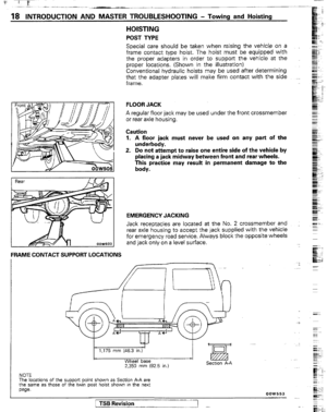
HOISTING
POST TYPE
Special care should be taken when raising the vehicle on a
frame contact type hoist. The hoist must be equipped with
the proper adapters in order to support the vehicle at the
proper locations. (Shown in the illustration)
Conventional hydraulic hoists may be used after determining
that the adapter plates will make firm contact with the side ._
frame.
FLOOR JACK
A regular floor jack may be used under the front crossmember
or rear axle housing.
Caution
1. A floor jack must never be used on any part of the
underbody.
2. Do not attempt to raise one entire side of the vehicle by
placing a jack midway between front and rear wheels.
This practice may result in permanent damage to the
body.
EMERGENCY JACKING
Jack receptacles are located at the No. 2 crossmember and .
rear axle housing to accept the jack supplied with the vehicle
for emergency road service. Always block the opposite wheels
and jack only on a level surface.
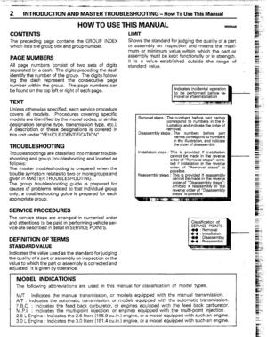
FRAME CONTACT SUPPORT LOCATIONS
1,175 mm (46.3 in.)
Wheel base
2.350 mm (92.5 in.) Sectlon A-A
NOTE
The
locations of the support point shown as Section A-A are
the same as those of the twin post hoist shown in the next
paw.
1 TSB Revision
I -
Page 19 of 30
INTRODUCTION AND MASTER TROUBLESHOOTING - Towing and Hoisting 19
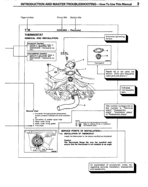
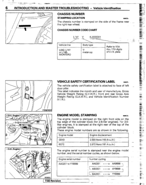
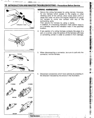
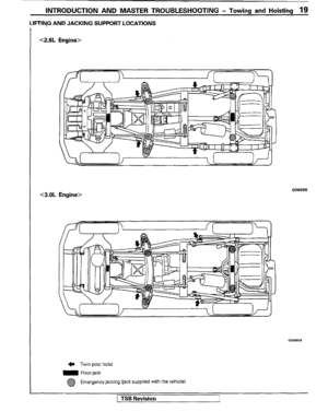
LIFTIYG AND JACKING SUPPORT LOCATIONS
<2.6L Engine> <2.6L Engine>
<3.OL Engine> <3.OL Engine>
C Twin post hoist C Twin post hoist
m Floor jack m Floor jack
@ @ Emergency jacking (jack supplied with the vehicle) Emergency jacking (jack supplied with the vehicle)
TSB Revision TSB Revision
Page 20 of 30

Overall len")
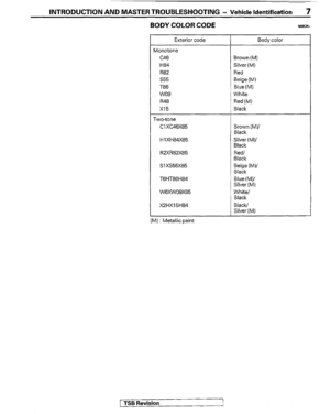
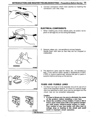
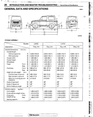
20 INTRODUCTION AND MASTER TROUBLESHOOTING - General Data and Specifications
GENERAL DATA AND SPECIFICATIONS NW-
<2-door vehicles>
Models L047.G
ascription
chicle dimensions mm (in.)
Overall length
Without spare tire 0
With spare tire 8
Overall width @
Overall height
@
Wheelbase c3
Tread Front @
Rear 6
Overhang
Front @
Rear (9,
Height at curb weight (wt.)
Front bumper to ground @
Rear bumperto ground 0
Minimum running ground 0
clearance
Angle of approach 8
Angle of departure 8
Ramp breakover angle -33
hicle weights kg (Ibs.)
Curb weight
Gross vehicle weight rating
Gross axle Front
weight rating
Rear
Seating capacity TNSL F/H
3,900 (153.5)
3,935 (154.9)
1,680 (66.1)
1,840 (72.4)
2,350 (92.5)
1,400 (55.1)
1,375 (54.1)
685 (27.0)
900 (35.4)
480(18.9)
440(17.3)
210(8.3)
38”
28”
21”
1,455 (3.207)
1,910(4.210)
1 ,I 00 (2.425)
1,450 (3.197)
2 T
TNJL F/H
3,905 (153.7)
3,940(155.1)
1,680 (661)
1,850 (72.8)
2,350 (92.5)
1,400 (551)
1,415 (55.7)
685 (27.0)
905 (35.6)
490 (19.3)
450 (17.7)
215 (8.5)
38”
28”
21°
1,585 (3,494)
2,200 (4,850)
1,100 (2,425)
1,600 (3,527)
2 L141G
TRJL F/W
3,905 (153.7)
3,940(155.1)
1,880 (66.1)
1,850 (72.8)
2,350 (92.5)
1,400(55.1)
1,415 (55.7)
685 (27.0)
905 (35.6)
490(19.3)
450(17.7)
215(8.5)
38”
28”
21”
1,600 (3.527)
2,200 (4,850)
1,100 (2,425)
1,600 (3,527)
2 TRUL F/H
3,905 (153.7)
3,940(155.1)
1,680 (66.1)
1,850 (72.8)
2,350 (92.5)
1,400 (55.1)
1,415 (55.7)
685 (27.0)
905 (35.6)
490 (19.3)
450 (17.7)
215 (8.5)
38”
28”
21”
1,605 (3,538)
2,200 (4,850)
1,100 (2,425)
1,600 (3,527)
2
;--- -. . I I TSB Revision
Page 21 of 30

INTRODUCTION AND MASTERTROUBLESHOOTING - GeneralDataandSpecmcations 21
L042G L141G
TNSL FM TNJL F/H
TRJL F/H TRUL F/H
Engine
Model No. G54B 6672 6672 6672
Type In-line OHC V-type, OHC V-type, OHC
V-type, OHC
Number of cylinders 4 6 6 6
Bore 91.1 mm(3.59in.j 91.1 mm(3.59in.j 91.1 mm(3.59in.) 91.1 mm(3.59in.
Stroke 98.0 mm (3.86 in.) 76.0 mm (2.99 in.) 76.0 mm (2.99 in.) 76.0 mm (2.99 in.
Piston displacement 2,555 cm3 2,972 cm3 2,972 cm3 2,972 cm3
(155.9 cuin.) (181.4cu.in.) (181.4cu.in.) (181.4 cuin.)
Compression ratio 8.7 8.9 8.9 8.9
Firing order 1-3-4-2 1-2-3-4-5-6 I -2-345-5 1-2-3-4.5-8
Basic ignition timing 7”BTDC 22” 5”BTDC 22” 5”BTDC i 2” 5”BTDC +-2”
Transmission &transfer case
Model No. KM145 V5MTl KM148 KM148
Type S-speed manual 5-speed manual &peed automatic &peed automatic
Gear ratio
Transmission 1st 3.967 3.918 2.826 2.826
2nd 2.136 2.261 1.493 1.493
3rd 1.360 1.395 1 .ooo 1.000
4th 1 .ooo 1.000 0.688 0.688
5th 0.856 0.829 -
Reverse 3.587 3.925 2.703 2.703
Transfer case High 1 .ooo 1 .ooo 1 .ooo 1 .ooo
Low 1.944 1.925 1.925 1.925
Final ring ratio gear 4.625 4.625 4.625 4.625
Clutch
Type Dry single disc & Dry single disc & -
diaphragm spring diaphragm spring
Chassis
Tire size
Front suspension
Type
Rear suspension
Type
Brakes
Type Front
Rear P225ff 5Rl5 P235ff5Rl5
independent Independent double-wishbone
double-wishbone
Rigid axle Rigid axle
Disc Disc
Drum Drum (Leading and trailing)
(Leading and trailing)
Power steering
Gear type
Gear ratio
Fuel tank capacity Integral type Integral type (Recirculating ball nut)
(Recirculating ball nut)
16.4 16.4
liters (gals.) 60 (15.9) 75 (19.8)
[ TSB Revision
Page 22 of 30

Overall length
Withoutspare tire a
With spare tire @
Overall wid")
-_-
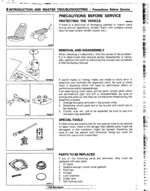
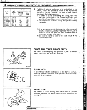
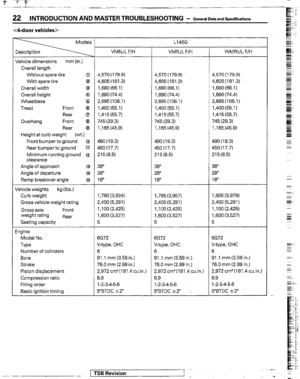
22 INTRODUCTION AND MASTER TROUBLESHOOTING - General Data and Specifications
<&door vehicles>
L-
chicle dimensions mm (in.)
Overall length
Withoutspare tire a
With spare tire @
Overall width 0
Overall height @
Wheelbase Q
Tread Front @
Rear 8
Overhang Front @
Rear @
Height at curb weight
Wt.)
Front bumperto ground @
Rear bumper to ground 0
Minimum running ground @
clearance
Angle of approach 8
Angle of departure
8
Ramp breakover angle
63
,hicle weights kg (Ibs.)
Curb weight
Gross vehicle weight rating
Gross axle Front
weight rating
Rear
Seating capacity
gine
Model No.
Type
Number of cylinders
Bore
Stroke
Piston displacement
Compression ratio
Firing order
Basic ignition timing VMNJL F/H VMRJL F/H
4,570 (179.9)
4,605 (181.3)
1,680 (66.1)
1,890 (74.4)
2,695 (106.1)
1,400 (55.1)
I,41 5 (55.7)
745 (29.3)
1 ,I 65 (45.9) 4,570 ( 179.9)
4,605(181.3)
1,680 (66.1)
1,890 (74.4)
2,695(106.1)
1.400(55.1)
1,415 (55.7)
745 (29.3)
1,165(45.9)
490 (19.3)
450(17.7)
215 (8.5) 490 (19.3)
450(17.7)
215 (8.5)
38”
28”
18” 38”
28
18”
-i
1,780 (3,924)
2,400 (5,291)
1,100(2,425)
1,600 (3,527)
5 1,795 (3,957)
2,400 (5,291)
1,100(2.425)
1,600 (3,527)
5
6672
V-type, OHC
6
91 .I mm (3.59 in.)
76.0 mm (2.99 in.)
2,972 cm3 (181.4 cu.in.)
8.9
l-2-3-4-5-6
5”BTDC i2” 6672
V-type, OHC
6
91 .l mm (3.59 in.)
76.0 mm (2.99 in.)
2,972 cm3 (181.4 cuin.)
8.9
1-2-3-4-5-6
5”BTDC 22” : L146G
L
_-. 1 TSB Revision I
.- WMRUL F/H
4.570 (179.9)
4,605 (181.3)
1,680 (66.1)
1,890 (74.4)
2,695(106.1)
1,400(55.1)
1,415 (55.7)
745 (29.3)
1,165 (45.9)
490 (19.3)
450 (17.7)
215 (8.5)
38”
28”
18
1,805 (3,979)
2,400 (5,291)
1 ,100 (2,425)
1,600 (3,527)
5
3072
V-type, OHC
3
31 .l mm (3.59 in.)
76.0 mm (2.99 in.)
2,972 cm3 (181.4 cu.in.)
3.9
l-2-3-4-5-6
5”BTDC 22”
Page 23 of 30
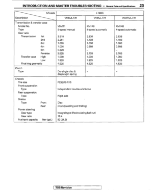
INTRODUCTION AND MASTER TROUBLESHOOTING - General Dataand Swxifications 23
Transmission &transfer case
Model No.
Type
Gear ratio
Transmission 1 St
2nd
3rd
4th
5th
Reverse
Transfer case High
Low
Final ring gear ratio
Elutch
Type
Chassis
Tire size
Front suspension
Type
Rear suspension
Type
Brakes
Type Front
Rear
Power steering
Gear type
Gear ratio
Fuel tank capacity liter (gal.) VMNJL F/H VMRJL F/H WMRUL F/H
EMT1 KM148 KM148
5-speed manual 4-speed automatic 4-speed automatic
3.918
2261
1.395
1.000
0.829
3.925
1.000
1.925
4.625 2.826 2.826
1.493 1.493
1 .ooo 1 .ooo
0.688 0.688
2.703
1 .ooo
1.925
4.625 -
2.703
1 .ooo
-1.925
4.625
Dry single disc &
diaphragm spring
P235ff 5 R 15 L146G
7
Independent doublewishbone
Rigid axle
Disc
Drum (Leading and trailing)
Integral type (Recirculating ball nut)
16.4
92 (24.3)
1 TSB Revision
Page 24 of 30
 mm
6x1.0
8x 1.25
10x1.25
12x 1.")
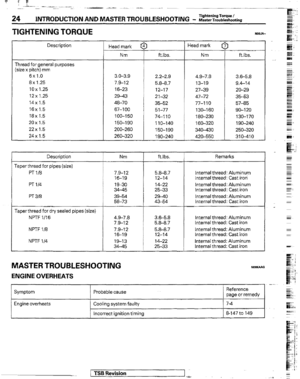
24 INTRODUCTION AND MASTER TROUBLESHOOTING - WasterTroubleshooting Tightening Torque I
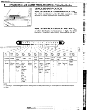
TIGHTENING TORQUE
Description
Thread for general purposes
(size x pitch) mm
6x1.0
8x 1.25
10x1.25
12x 1.25
14x 1.5
16x 1.5
18x 1.5
20x1.5
22x 1.5
24x 1.5
Description
Taper thread for pipes (size)
PT1/8
PT l/4
PT 3B
Taper thread for dry sealed pipes (size)
NF’TF l/16
NPTF l/8
NPTF l/4 Head mark f
Nm
3.0-3-s
7.9-12
16-23
29-43
46-70
67-l 00
100-150
150-190
ZOO-260
269-320 ft.lbs.
2.2-2.9 4.9-7.8
3.6-5.8
5.8-8.7 13-19 9.4-14
12-17 27-39 20-29
2’132 47-72 35-53
35-52 77-110 57-35
51-77 130-160 SO-120
74-110 180-230 130-170
110-140 160-320 1 go-240
150-190 340-430 250-320
1 go-240 420-550 310-410 Head mark [
Nm I
ft.lbs.
Nm ftlbs. Remarks
7.9-I 2 5.9-9.7 Internal thread: Aluminum
76-19 12-14 Internal thread: Cast iron
19-30 14-22 Internal thread: Aluminum
34-45 25-33 Internal thread: Cast iron
39-54 29-40 Internal thread: Aluminum
58-73 43-54 Internal thread: Cast iron
4.9-7.8 3.6-5.8 Internal thread: Aluminum
7.9-12 5.8-8.7 Internal thread: Cast iron
7.9-12 5.8-8.7 Internal thread: Aluminum
16-1s 12-14 Internal thread: Cast iron
19-13 14-22 Internal thread: Aluminum
34-45 25-33 Internal thread: Cast iron
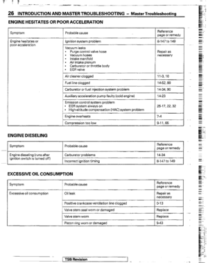
MASTER TROUBLESHOOTING NceKAAO
ENGINE OVERHEATS
Symptom Probable cause -
Reference
page or remedy
Engine overheats Cooling system faulty
Incorrect ignition timing
1 TSB Revision