Page 9 of 30

smo59
PARTS
When replacing parts, use MITSUBISHI genuine parts
VEHICLE WASHING
If high-pressure car-washing equipm")
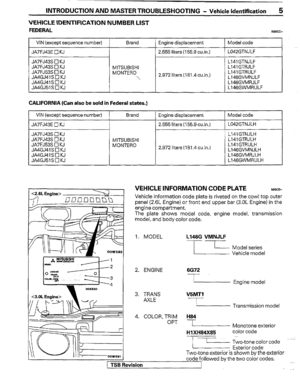
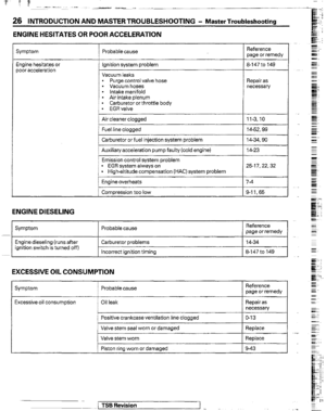
INTRODUCTION AND MASTER TROUBLESHOOTING - Precautions Before Service 9
nm (in.)
smo59
PARTS
When replacing parts, use MITSUBISHI genuine parts
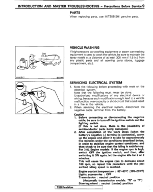
VEHICLE WASHING
If high-pressure car-washing equipment or steam car-washing
equipment is used to wash the vehicle, be sure to maintain the
spray nozzle at a distance of at least 300 mm (11.8 in.) from
any plastic parts and all opening parts (doors, luggage
compartment, etc.).
SERVICING ELECTRICAL SYSTEM
1. Note the following before proceeding with work on the
electrical system.
Note that the following must never be done:
Unauthorized modifications of any electrical device or
wiring, because such modifications might lead to a vehicle
malfunction, over-capacity or short-circuit that could result
in a fire in the vehicle.
2. When servicing the electrical system, disconnect the
negative cable terminal from the battery.
Caution
1. Before connecting or disconnecting the negative
cable, be sure to turn off the ignition switch and the
fighting switch.
(If this is not done, there is the possibility of
semiconductor parts being damaged.)
2. After completion of the work steps [when the
battery’s negative (-) terminal is connected], warm
up the engine and allow it to idle for approximately
five minutes under the conditions described below,
in order to stabilize engine control conditions, and
then check to be sure that the idling is satisfactory.
For 3.OL Engine models: If the engine rpm is high,
switch OFF the ignition switch, and then, after
switching it ON again, let the engine idle for 2 or 3
minutes.
This will cause the engine rpm to decrease about
100 rpm, so repeat this procedure until the pre-
scribed idling speed is reached.
Engine coolant temperature : 85”-95°C (‘l85403”F)
Lights, accessories : OFF
Transmission : neutral position
(Automatic transmission models: “IV or “P”J
Steering wheel : neutral (center) position
1 TSB Revision
Page 10 of 30
10 INTRODUCTION AND MASTER TROUBLESHOOTiNG - Precautions Before Service
F1617
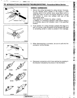
WIRING HARNESSES
1. Secure the wiring harnesses by using clamps. However,
for any harness which passes to the engine or other
vibrating parts of the vehicle, allow some slack within a
range that does not allow the engine vibrations to cause
the harness to come into contact with any of the
surrounding parts.
Then secure the harness by using a clamp.
In addition, if a mounting indication mark (yellow tape) is
on a harness, secure the indication mark in the specified
location.
2. If any section of a wiring harness contacts the edge of a
part, or a corner, wrap the section of the harness with tape
or something similar in order to protect it from damage.
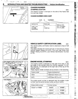
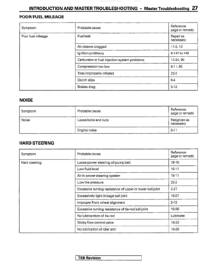
3. When disconnecting a connector, be sure to pull only the
connector, not the harness.
4. Disconnect connectors which have catches by pressing in
the direction
indicated by the arrows in the illustration.
Page 11 of 30

INTRODUCTION AND MASTER TROUBLESHOOTING - Precautions Before Servicre 11
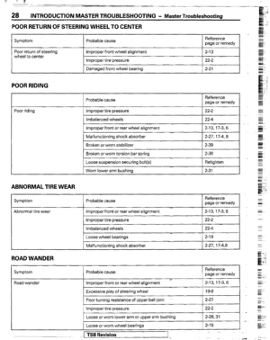
5. Connect connectors which have catches by inserting the
connectors until they snap.
I
I cwE331
I
10A 15A
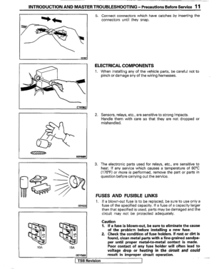
ELECTRICAL COMPONENTS
1. When installing any of the vehicle parts, be careful not to
pinch or damage any of the wiring harnesses.
2. Sensors, relays, etc., are sensitive to strong impacts.
Handle them with care so that they are not dropped or
mishandled.
3. The electronic parts used for relays, etc., are sensitive to
heat. If any service which causes a temperature of 80°C
(176°F) or more is performed, remove the part or parts in
question before carrying out the service.
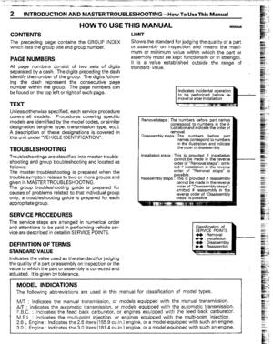
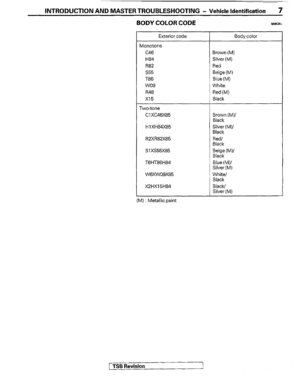
FUSES AND FUSIBLE LINKS
1. If a blown-out fuse is to be replaced, be sure to use only a
fuse of the specified capacity. If a fuse of a capacity larger
than that specified is used, parts may be damaged and the
circuit may not be protected adequately.
Caution
1. If a fuse is blown-out, be sure to eliminate the cause
of the problem before installing a new fuse.
2. Check the condition of fuse holders. If rust or dirt is
found, clean metal parts with a fine-grained sandpa-
per until proper metal-to-metal contact is made.
Poor contact of any fuse holder will often lead to
voltage drop or heating
in the circuit and could
result in improper circuit operation. 1 cnlY589
(SB Revision
1
Page 12 of 30

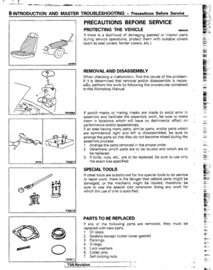
12 INTRODUCTION AND MASTER TROUBLESHOOTING - Precautions Before Service
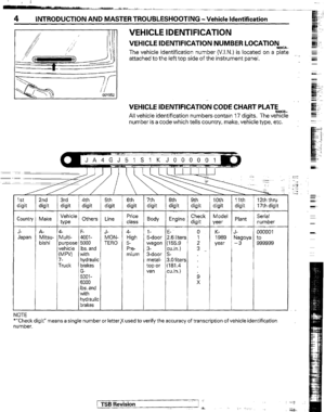
Nominal
size
0.3 mm2
0.5 mm2
0.85 mm*
1.25 mm2
2.0 mm*
3.0 mm2
5.0 mm2 Permissible current
SAE
I
Other
areas
2. If additional optional equipment is to be installed in the
vehicle, follow the procedure listed in the appropriate
instruction manual; however, be sure to pay careful
attention to the following points:
(1) In order to avoid overloading the wiring, take the
electrical current load of the optional equipment into
consideration, and determine the appropriate wire size.
(2) Where possible, route the wiring through the existing
harnesses.
(3) If an ammeter or similar instrument is to be connected
to a live-wire circuit, use tape to protect the wire, use a
clamp to secure the wire, and make sure that there is
no contactwith any other parts.
(4) Be sure to provide a fuse for the load circuit of the
optional equipment.
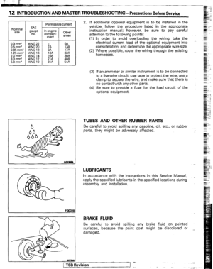
TUBES AND OTHER RUBBER PARTS
Be careful to avoid spilling any gasoline, oil, etc., or rubber
parts, they might be adversely affected.
LUBRICANTS
In accordance with the instructions in this Service Manual,
apply the specified lubricants in the specified locations during
assembly and installation.
BRAKE FLUID
Be careful to avoid spilling any brake fluid on painted
surfaces, because the paint coat might be discolored or
damaged.
Page 13 of 30

INTRODUCTION AND MASTER TROUBLESHOOTING - t+mwtions Before Service ‘I3
DOING SERVICE WORK IN GROUPS OF TWO OR
MORE TECHNICIANS
If the service work is to be done by two or more technicians
working together, extra caution must be taken.
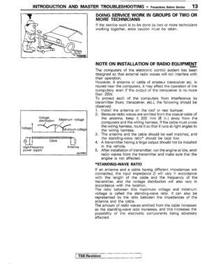
NOTE ON INSTALLATION OF RADIO EQUlPM$ihl-
The computers of the electronic control system has been
designed so that external radio waves will not interfere with
their operation.
However, if antenna or cable of amateur transceiver etc. is
routed near the computers, it may affect the operation of the
computers. even if the output of the transceiver is no more
than 25W.
To protect each of the computers from interference by
transmitter (hum, transceiver, etc.). the following should be
observed.
1. Install the antenna on the roof or rear bumper.
2. Because radio waves are emitted from the coaxial cable of
the antenna, keep it 200 mm (8 in.) away from the
computers and the wiring harness. If the cable must cross
the wiring harness, route it so that it runs at right angles to
the wiring harness.
3. The antenna and the cable should be well matched, and
the standing-wave ratio” should be kept low.
4. A transmitter having a large output should not be installed
in the vehicle.
5. After installation of transmitter, run the engine at idle, emit
radio waves from the transmitter and make sure that the
engine is not affected.
*STANDING-WAVE RATIO
If an antenna and a cable having different impedances are
connected, the input impedance Zi will vary in accordance
with the length of the cable and the frequency of the
transmitter, and the voltage distribution will also vary in
accordance with the location.
The ratio between this maximum voltage and minimum
voltage is called the standing-wave ratio. It can also be
represented by the ratio between the impedances of the
antenna and the cable.
The amount of radio waves emitted from the cable increases
as the standing-wave ratio increases, and this increases the
possibility of the electronic components being adversely
affected.
1 TSB Revision
I
Page 14 of 30
,’ i 1;
h-J ” ^ .
14 Treatment Before I INTRODUCTION AND MASTER TROUBLESHOOTING - AftertheFotiingofastmsm
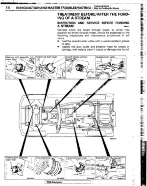
TREATMENT BEFORE/AFTER THE FORD-
ING OF A STREAM
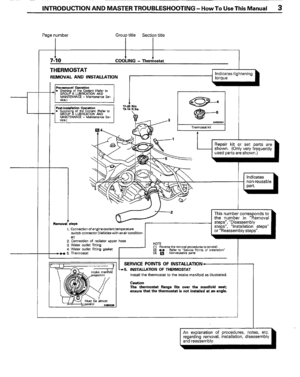
INSPECTION AND SERVICE BEFORE FORDING
A STREAM NOW%-
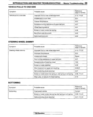
Vehicles which are driven through water, or which may
possibly be driven through water, should be subjected to the
following inspections and maintenance procedures in ad-
vance.
e Seal the speedometer cable with a water-resistant grease ~_
or tape.
a Inspect the dust boots and breather hose for cracks or
damage, and replace them if cracks or damage are found.
,- . 1^. dometer cable 1
Steering joint assembly
/ 1 Drive shaft boot -\l(. ‘/ Torsion bar dust cover 1 Breath& hose==
OOW528
( TSB Revision -
Page 15 of 30
Treatment Before / INTRODUCTION AND MASTER TROUBLESHOOTING - AftertheFordingofaStream I5
l Apply grease to the lubricating points of the front suspen-
sion, steering linkage and propeller shaft.
TSB Revision
Page 16 of 30
16 Treatment Before I INTRODUCTION AND MASTERTROUBLESHOOTING - AftertheFordingofaStream
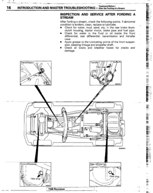
INSPECTION AND SERVICE AFTER FORDING A
STREAM
After fording a stream, check the following points. If abnormal
condition is evident, clean, replace or lubricate.
= Check for water. mud. sand. etc. in the rear brake drum.
clutch housing, &tarte; mot&, brake pipe and fuel pipe:
Check for water in the fluid or oil inside the front
differential. rear differential, transmission and transfer
case.
Apply grease to the lubricating points of the front suspen-
sion, steering linkage and propeller shaft.
Check all boots and breather hoses for cracks and
damage.
rTSB Revi