1989 MAZDA 323 warning
[x] Cancel search: warningPage 253 of 1164
ENGINE COOLANT E
ENGINE COOLANT
PREPARATION
SST
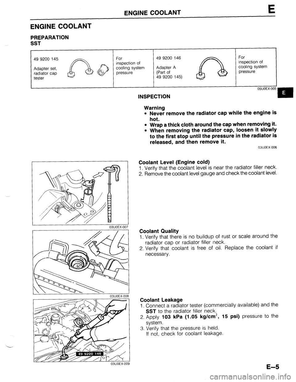
49 9200 145
For 49 9200 146
For
inspection of inspection of
cooling system Adapter A cooling system
pressure (Part of pressure
49 9200 145)
05UOEX-00
INSPECTION
Warning
l Never remove the radiator cap while the engine is
hot.
l Wrap a thick cloth around the cap when removing it.
l When removing the radiator cap, loosen it slowly
to the first stop until the pressure in the radiator is
released, and then remove it.
03UOEX~006
Coolant Level (Engine cold)
1. Verify that the coolant level is near the radiator filler neck.
2. Remove the coolant level gauge and check the coolant level.
Coolant Quality
1. Verify that there is no buildup of rust or scale around the
radiator cap or radiator filler neck.
2. Verify that coolant is free of oil. Replace the coolant if
necessary.
Coolant Leakage
1. Connect a radiator tester (commercially available) and the
SST to the radiator filler neck.
2. Apply
103 kPa (1.05 kg/cm2, 15 psi) pressure to the
system.
3. Verify that the pressure is held.
If not, check for coolant leakage.
E-5
Page 254 of 1164
E ENGINE COOLANT
SPECIFIC
GRAVITY COOLANT PROTECTION
l.OOd ’ ’ I I I I I
0, I I
-10 0 i 10 20 30 40 50 60
70 60 90
(14) (32) (50) (66) (66)(104)(122)(140)(158~176)(194)
COOLANT TEMPERATURE OC (OF)
Coolant Protection
Caution
l Do not use alcohol- or methanol-based coolant.
l Use only soft (demineralized) water in the coolant
mixture.
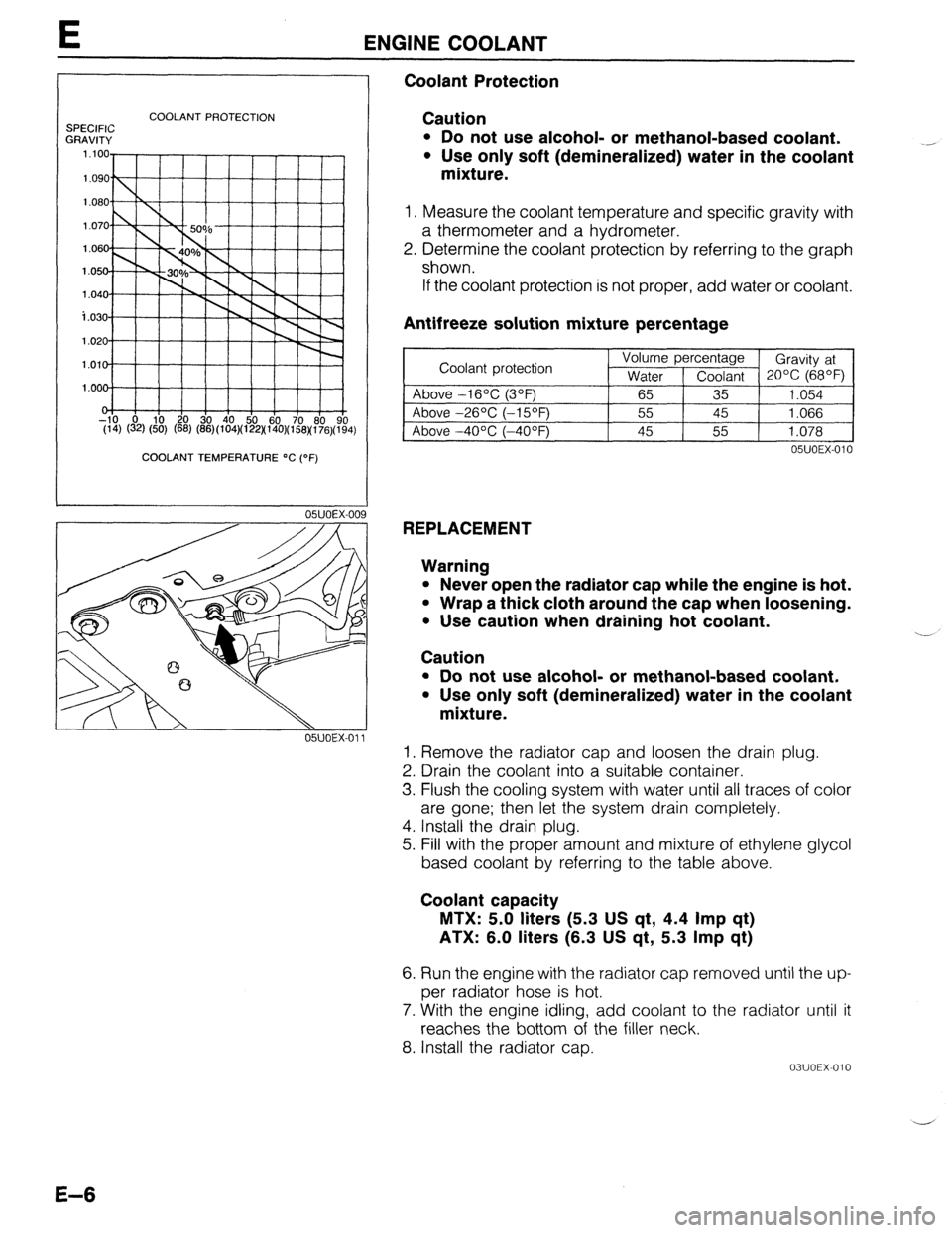
1. Measure the coolant temperature and specific gravity with
a thermometer and a hydrometer.
2. Determine the coolant protection by referring to the graph
shown.
If the coolant protection is not proper, add water or coolant.
Antifreeze solution mixture percentage
~1
05UOEX-010
REPLACEMENT
Warning
l Never open the radiator cap while the engine is hot.
l Wrap a thick cloth around the cap when loosening.
. Use caution when draining hot coolant.
Caution ..-
l Do not use alcohol- or methanol-based coolant.
l Use only soft (demineralized) water in the coolant
mixture.
1. Remove the radiator cap and loosen the drain plug.
2. Drain the coolant into a suitable container.
3. Flush the cooling system with water until all traces of color
are gone; then let the system drain completely.
4. Install the drain plug.
5. Fill with the proper amount and mixture of ethylene glycol
based coolant by referring to the table above.
Coolant capacity
MTX: 5.0 liters (5.3 US qt, 4.4 Imp qt)
ATX: 6.0 liters (6.3 US qt, 5.3 Imp qt)
6. Run the engine with the radiator cap removed until the up-
per radiator hose is hot.
7. With the engine idling, add coolant to the radiator until it
reaches the bottom of the filler neck.
8. Install the radiator cap.
03UOEX-010 -
E-6
Page 265 of 1164
RADIATOR THERMOSWITCH E
RADIATOR THERMOSWITCH
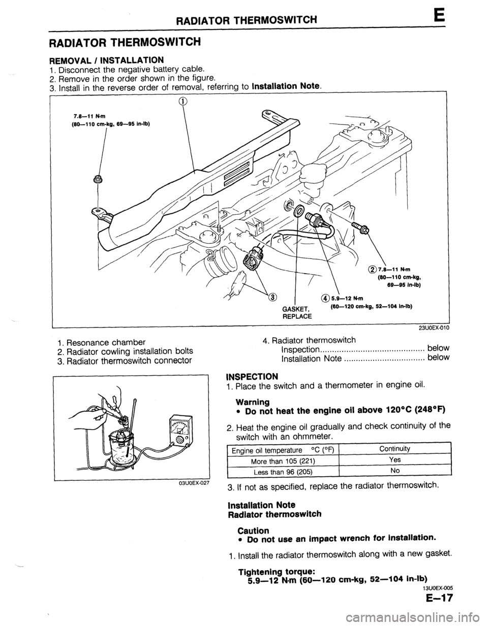
REMOVAL / INSTALLATION
1. Disconnect the negative battery cable.
2. Remove in the order shown in the figure.
3. Install in the reverse order of removal. referrina to
Installation Note.
(80-110 cm-kg,
69-95 in-lb)
GAdKET,
REPLACE (60-120 cm-kg, 52-104 In-lb)
1. Resonance chamber
2. Radiator cowling installation bolts
3. Radiator thermoswitch connector 4. Radiator thermoswitch
Inspection . . . . . . . . . . . . . . . ..*...,..,..................* below
Installation Note ..,.,........,.......,........,... below
1. Place the switch and a thermometer in engine oil.
03UOEX-02
INSPECTION
Warning
l Do not heat the engine oil above 120°C (248OF)
2. Heat the engine oil gradually and check continuity of the
switch with an ohmmeter.
Engine oil temperature OC (OF) Continuity
More than 105 (221)
Yes
Less than 96 (205) No
3. If not as specified, replace the radiator thermoswitch.
lnstallatlon Note
Radiator thermoswitch
Caution
l Do not use an impact wrench for installation.
1. Install the radiator thermoswitch along with a new gasket.
Tightening torque:
5.9-12 N#m (60-l 20 cm-kg, 52-104 in-lb)
13UOEX-005
E-17
Page 343 of 1164
![MAZDA 323 1989 Factory Repair Manual TROUBLESHOOTING GUIDE
27 MIL ALWAYS ON
DESCRIP- *Self-Diagnosis Checker does not indicate Malfunction Code No. but MIL always ON
TION
[TROUBLESHOOTING HINTS]
*Short circuit in wiring harness
l E MAZDA 323 1989 Factory Repair Manual TROUBLESHOOTING GUIDE
27 MIL ALWAYS ON
DESCRIP- *Self-Diagnosis Checker does not indicate Malfunction Code No. but MIL always ON
TION
[TROUBLESHOOTING HINTS]
*Short circuit in wiring harness
l E](/manual-img/28/57053/w960_57053-342.png)
TROUBLESHOOTING GUIDE
27 MIL ALWAYS ON
DESCRIP- *Self-Diagnosis Checker does not indicate Malfunction Code No. but MIL always ON
TION
[TROUBLESHOOTING HINTS]
*Short circuit in wiring harness
l ECU malfunction
iTEF 1
1
-
s
Disconnect (Y/B) wire from ECU and check if
MIL goes off
‘YIB
ATX YIB
INSPECTION ACTION
Yes Replace ECU CT page F-149
No Check for short circuit in wiring be-
tween instrument cluster and ECU
23UOFX-042
28
MIL NEVER ON
IESCRIP- *Self-Diagnosis Checker indicates Malfunction Code No. of input device but MIL never ON
RON *Other indicator and warning lamps OK
:TROUBLESHOOTING HINTS]
b Bulb burned
‘Open circuit in wiring harness
m ECU malfunction
TEP INSPECTION
ACTION
1 Ground (Y/B) wire at ECU with jumper wire and
Yes Check connection of ECU connector
check if MIL comes on
MTX e If OK, replace ECU w page F-149
I- i -!~ !r--~r’:~;-‘;- --~_:- ,
1 i r 1 1 1 ;-.:,~;~$~& {-;&# ,$&]j 4 If not OK, repair ECU connector
! No
Check if bulb is OK
ATX 13 If OK, repair (Y/B) wire between
ECU and instrument cluster
e If not OK, replace bulb CT page T-83
23UOFX-043
29 A/C DOES NOT WORK
DESCRIP- *Blower fan operates but magnet clutch does not operate
TION
[TROUBLESHOOTING HINTS]
*Open or short circuit in wiring harness
*A/C relay, A/C switch, or magnetic clutch malfunction
l ECU malfunction
TEP/ INSPECTION ACTION
1 1 Check ECU
terminal 10 (MTX) 10 (ATX) voltage 1
Yes Check ECU terminal 1 J (MTX) 1 L (ATX)
OK
CT= page F-152
MTX
T7J++!;i”-
L
ATX
No voltage OK
CT page F-152
1-3 If OK, check A/C system
c3- page U-30
~3 If not OK, replace ECU CT page F-149
Check for cause w page F-153
F-77
Page 344 of 1164
F ENGINE TUNE-UP
ENGINE TUNE-UP
PREPARATlON
SST
I
I I
49 BO19 9AO
System Selector For
inspection of igni-
tion timing and
idle speed
hA ‘I
03UOFX-04
03UOFX-04
03UOFX-04
NG POINT
03UOFX-04 03UOFX-045
BASIC INSPECTION
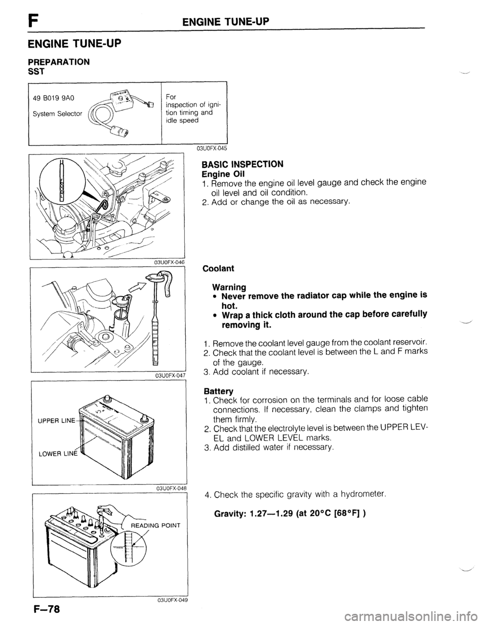
Engine Oil
1. Remove the engine oil level gauge and check the engine
oil level and oil condition.
2. Add or change the oil as necessary.
Coolant
Warning
l Never remove the radiator cap while the engine is
hot.
l Wrap a thick cloth around the cap before carefully
removing it.
1. Remove the coolant level gauge from the coolant reservoir.
2. Check that the coolant level is between the L and F marks
of the gauge.
3. Add coolant if necessary.
Battery
1. Check for corrosion on the terminals and for loose cable
connections. If necessary, clean the clamps and tighten
them firmly.
2. Check that the electrolyte level is between the UPPER LEV-
EL and LOWER LEVEL marks.
3. Add distilled water if necessary.
4. Check the specific gravity with a hydrometer.
Gravity: 1.27-l .29 (at 20% [68OF] )
Page 387 of 1164
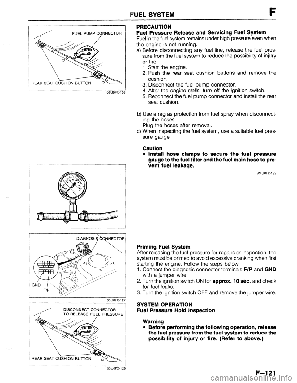
FUEL PUMP CONNECTOR
/
REAR SEAT C
FUEL SYSTEM F
PRECAUTION
Fuel Pressure Release and Servicing Fuel System
Fuel in the fuel system remains under high pressure even when
the engine is not running.
a) Before disconnecting any fuel line, release the fuel pres-
sure from the fuel system to reduce the possibility of injury
or fire.
1. Start the engine.
2. Push the rear seat cushion buttons and remove the
cushion.
3. Disconnect the fuel pump connector.
4. After the engine stalls, turn off the ignition switch.
5. Reconnect the fuel pump connector and install the rear
seat cushion.
b) Use a rag as protection from fuel spray when disconnect-
ing the hoses.
Plug the hoses after removal.
c) When inspecting the fuel system, use a suitable fuel pres-
sure gauge.
Caution
l Install hose clamps to secure the fuel pressure
gauge to the fuel filter and the fuel main hose to pre-
vent fuel leakage.
9MUOF2-122 OBUOFX-126
DlAGNOS&O,NNECTOR
03UOFX-12.
-
DISCONNECT CONNECTOR
/ TO RELEASE FUEL PRESSURE
03UOFX-12;
Priming Fuel System
After releasing the fuel pressure for repairs or inspection, the
system must be primed to avoid excessive cranking when first
starting the engine. Follow the steps below.
1. Connect the diagnosis connector terminals
F/P and GND
with a jumper wire.
2. Turn the ignition switch
ON for approx. 10 sec. and check
for fuel leaks.
3. Turn the ignition switch OFF and remove the jumper wire.
SYSTEM OPERATION
Fuel Pressure Hold Inspection
Warning
l Before performing the following operation, release
the fuel pressure from the fuel system to reduce the
possibility of injury or fire. (Refer to above.)
F-121
Page 388 of 1164
F FUEL SYSTEM
OSUOFX-129
DIAGNOSIS.\CO.NNECTOR j
/, I 23UOFX-104
DISCONNECT CONNECTOR
TO RELEASE FlJsL PRESSURE
L 23UOFX-105
INSTALL CLAMPS
DIAGNOSI$kO)lNECTOfl
I
23UOFX-ll
F-l 22
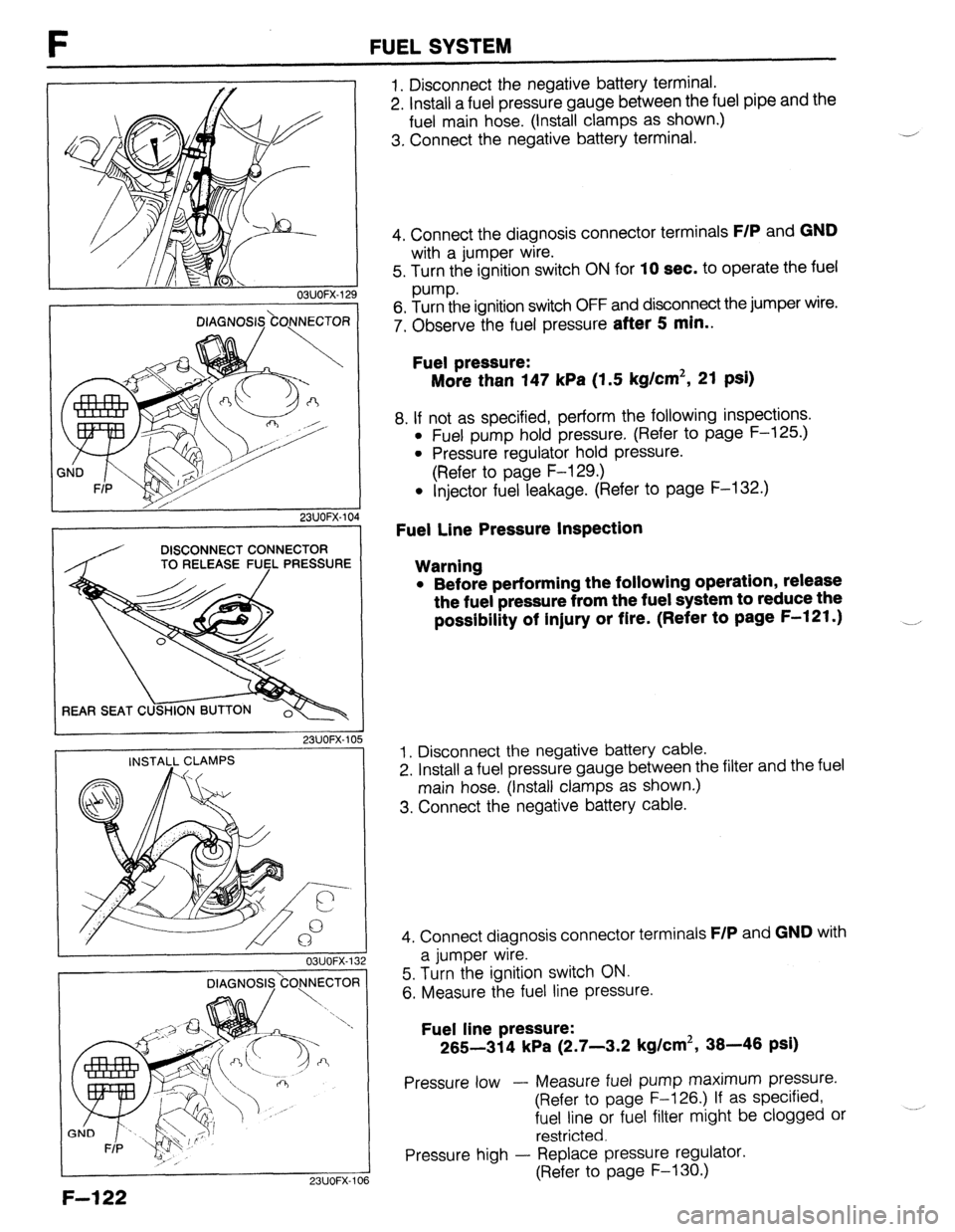
1. Disconnect the negative battery terminal.
2. Install a fuel pressure gauge between the fuel pipe and the
fuel main hose. (Install clamps as shown.)
3. Connect the negative battery terminal. J
4. Connect the diagnosis connector terminals
F/P and GND
with a jumper wire.
5. Turn the ignition switch ON for
10 sec. to operate the fuel
pump.
6. Turn the ignition switch OFF and disconnect the jumper wire.
7. Observe the fuel pressure
after 5 min..
Fuel pressure:
More than 147 kPa (1.5 kg/cm2, 21 psi)
8. If not as specified, perform the following inspections.
l Fuel pump hold pressure. (Refer to page F-125.)
l Pressure regulator hold pressure.
(Refer to page F-129.)
l Injector fuel leakage. (Refer to page F-132.)
Fuel Line Pressure Inspection
Warning
l Before performing the following operation, release
the fuel pressure from the fuel system to reduce the
possibility of injury or fire. (Refer to page F-121.) __,
1. Disconnect the negative battery cable.
2. Install a fuel pressure gauge between the filter and the fuel
main hose. (Install clamps as shown.)
3. Connect the negative battery cable.
4. Connect diagnosis connector terminals
F/P and GND with
a jumper wire.
5. Turn the ignition switch ON.
6. Measure the fuel line pressure.
Fuel line pressure:
265-314 kPa (2.7-3.2 kg/cm2, 38-46 psi)
Pressure low - Measure fuel pump maximum pressure.
(Refer to page F-126.) If as specified,
fuel line or fuel filter might be clogged or
restricted.
Pressure high - Replace pressure regulator.
(Refer to page F-130.)
Page 389 of 1164
FUEL SYSTEM F
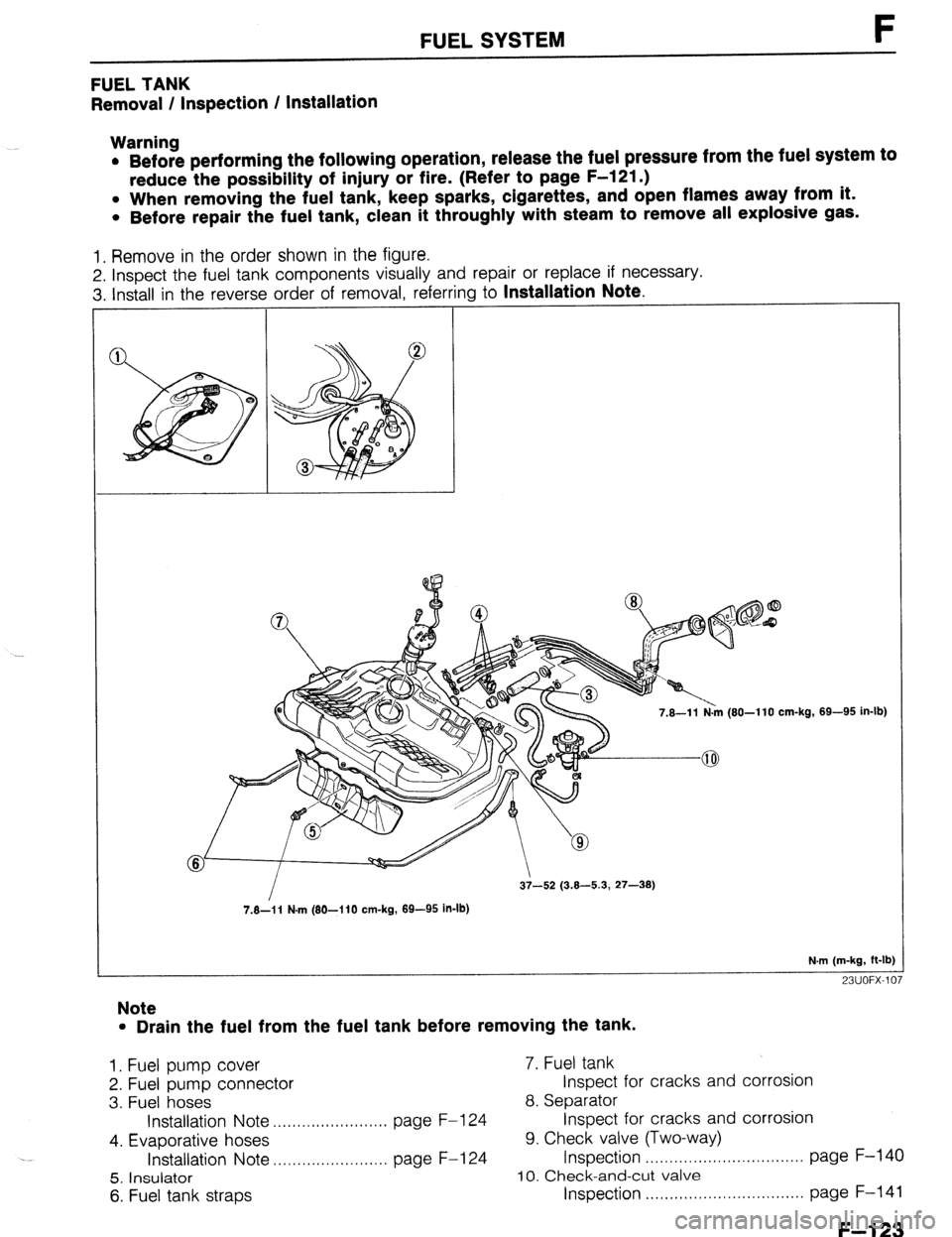
FUEL TANK
Removal / Inspection / Installation
Warning
l Before performing the following operation, release the fuel pressure from the fuel system to
reduce the possibility of injury or fire. (Refer to page F-121 .)
l When removing the fuel tank, keep sparks, cigarettes, and open flames away from it.
l Before repair the fuel tank, clean it throughly with steam to remove all explosive gas.
1. Remove in the order shown in the figure.
2. Inspect the fuel tank components visually and repair or replace if necessary.
3. Install in the reverse order of removal, referring to
Installation Note.
7.8-l 1 N.m (80-l 10 cm-kg,
7.8-i 1 N-m (80-I 10 cm-kg, 89-95 in-lb) 69-95 in-lb)
N.m (m-kg, ft-lb]
23UOFX-107
Note
l Drain the fuel from the fuel tank before removing the tank.
1. Fuel pump cover 7. Fuel tank
2. Fuel pump connector Inspect for cracks and corrosion
3. Fuel hoses 8. Separator
Installation Note . ..., I .I,,,,I,I,.,.I.,,. page F-l 24 Inspect for cracks and corrosion
4. Evaporative hoses 9. Check valve (Two-way)
Installation Note ,..,..,................. page F-l 24 Inspection . . . . . . . . . . . . . . . . . . . . . . . . . . . . . . . . . page F-140
5. Insulator 10. Check-and-cut valve
6. Fuel tank straps Inspection . . . . . . . . . . . . . . . . . . . . . . . . . . . page F-141
F--l 23