Page 680 of 1164
P CONVENTIONAL BRAKE SYSTEM
0 8
500 mmHg
(19.7 inHg)
96 N (20 kg, 44 lb)
03UOPX-03
03UOPX-03
03UOPX-031
Loaded condition
1. Start the engine.
2. Depress the brake pedal with a force of 196 N (20 kg, 44
lb).
3. With the brake pedal depressed, stop the engine when the
vacuum gauge reading reaches 500 mmHg (19.7 inHg).
4. Observe the vacuum gauge for 15 seconds. If the gauge
shows 475-500 mmHg (18.7-19.7 inHg), the unit is
operating.
b) Checking for hydraulic pressure
1. If with the engine stopped (vacuum 0 mmHg) the fluid pres-
sure is within specification, the unit is operating.
Pedal force Fluid pressure
196 N (20 kg, 44 lb) 1 1,177 kPa (12 kg/cm2, 171 psi) min
2. Start the engine. Depress the brake pedal when the vacu-
um reaches 500 mmHg (19.7 inHg). If the fluid pressure
is within specification, the unit is operating.
Pedal force Fluid pressure
196 N (20 kg, 44 lb) 7,063 kPa (72 kg/cm’, 1,024 psi)
P-14
Page 682 of 1164

P CONVENTIONALBRAKESYSTEM
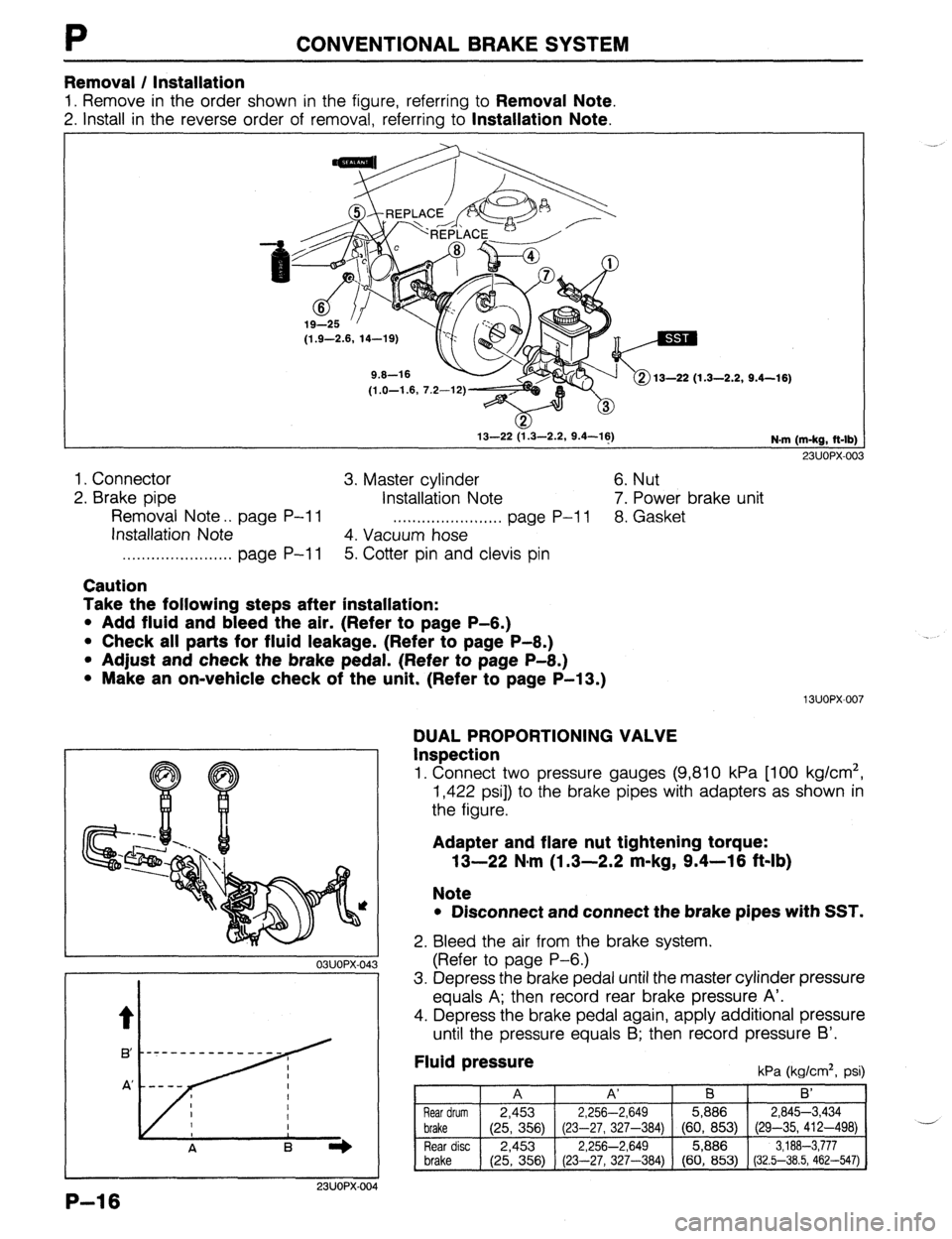
Removal / Installation
1. Remove in the order shown in the figure, referring to Removal Note.
2. install in the reverse order of removal, referring to Installation Note.
(1.9-2.6, 14-19)
1.3-2.2, 9.4-16)
(1 .O-1.6, 7.2-12)
13-22 (1.3-2.2, 9.4-16)
N.m (m-kg, ft-lb)
23UOPX-003
1. Connector 3. Master cylinder 6. Nut
2. Brake pipe
Installation Note 7. Power brake unit
Removal Note . . page P-l 1 . . . . . . . . . . . . . . . . . S ,,,.. page P-l 1 8. Gasket
Installation Note
4. Vacuum hose
. . . . . . . . . . . . . . . . . . . . . . . page P-l 1 5. Cotter pin and clevis pin
Cautlon
Take the following steps after installation:
l Add fluid and bleed the air. (Refer to page P-6.)
l Check all parts for fluid leakage. (Refer to page P-8.)
l Adjust and check the brake pedal. (Refer to page P-8.)
l Make an on-vehicle check of the unit. (Refer to page P-13.)
13uow007
03UOPX-043
t
0
A
.--- -------_- --
m--v
K/
6 B I)
P-l 6
DUAL PROPORTIONING VALVE
Inspection
1. Connect two pressure gauges (9,810 kPa [lo0 kg/cm’,
1,422 psi]) to the brake pipes with adapters as shown in
the figure.
Adapter and flare nut tightening torque:
13-22 N,m (1.3-2.2 m-kg, 9.4-18 f&lb)
Note
l Disconnect and connect the brake pipes with SST.
2. Bleed the air from the brake system.
(Refer to page P-6.)
3. Depress the brake pedal until the master cylinder pressure
equals A; then record rear brake pressure A’.
4. Depress the brake pedal again, apply additional pressure
until the pressure equals B; then record pressure 6’.
Fluid pressure kPa (kg/cm*, psi)
A A’ B B’
Rear drum 2,453 2,256-2,649 5,886 284%3,434
brake
(25, 356) (23-27, 327-384) (60, 853) (29-35, 412-498) --.-,
Rear disc 2,453 2,256-2,649 5,886 3,188-3,777
brake (25, 356) (23-27, 327-384) (60, 853) (32.5-38.5, 462-547)
Page 683 of 1164
CONVENTIONAL BRAKE SYSTEM P
Caution
l Do not attempt to adjust the dual proportioning
valve.
l After the inspection, bleed the air from the brake
system and check for fluid leakage.
l If the measurements are not within specification,
replace the valve assembly.
03UOPX-045
13-22 (1.3-2.2, 9.4-16) TJ
R P @ 19-23 (1.9-2.3, 14-17)
Replacement
1. Remove in the order shown in the figure, referring to Removal Note.
2. install in the reverse order of removal, referring to Installation Note.
13-22 (1.3-2.2, 9.4-16)
_-. .--.. ^. uwurx-047 N-m (m-kg, R-lb)
23UOPX-oc
1. Brake pipe 2. Bolt
Removal I Installation Note . . . . . . . . . . . . . . . . . Below 3. Dual proportioning valve
Removal / Installation note
Brake pipe
Loosen and tighten the brake pipes with the SST.
P-17
Page 685 of 1164
Removal / Installation
Caliper
1. Remove in the order shown in the figure.
2. Install in the reverse order of removal.
CONVENTIONAL BRAKE SYSTEM P
1
39-49 (4.0-5.0, 2! 3-36)
@ .-- . . -3
16-
‘(
N.m (m-kg, Mb)
23UOPX-023
1. Flexible hose 5. Caliper
2. Pad pin Disassembly / Inspection I
3. Disc pad assembly Assembly , . , , . , . . . . . . . . . . , . . . . . . . . . . . . . . . . . page P-21
Inspection . . . . . . . . . . . . . . . . . . . . . . . . . . . . . . . . . . . page P-20 6. Guide plate
7. Disc plate
Inspection . , . . . . . . . . . . . . . . . . . . . . . . . . . . . . . . . . . page P-20 4. Bolt
Caution
Take the following steps after installation:
l Add fluid and bleed the air. (Refer to page P-6.)
l Check for fluid leakage. (Refer to page P-8.)
l Depress the brake pedal a few tlmes and check that
the rear brakes do not drag While rotating the wheel.
03UOPX-052 P-19
Page 690 of 1164

CONVENTIONAL BRAKE SYSTEM
Installation note
Manual adjustment gear
1. Turn the manual adjustment gear clockwise until the brake
pads just touch the disc pIaTe.
2. Return the manual adjustment gear l/3-turn
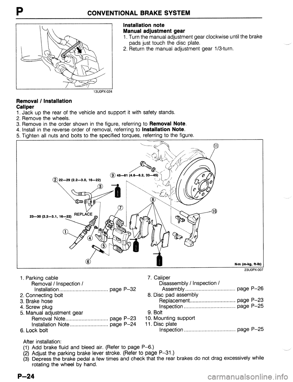
Removal / Installation
Caliper
1. Jack up the rear of the vehicle and support it with safety stands.
2. Remove the wheels.
3. Remove in the order shown in the figure, referring to
Removal Note.
4. Install in the reverse order of removal, referring to Installation Note.
5. Tighten all nuts and bolts to the specified torques, referring to the figure.
@ 22-29 (2.2-3.0, 16-22)
23-30 (2.2-3.1, 16-
N.m (m-kg, R-lb)
23UOPX-00
1. Parking cable 7. Caliper
Removal I Inspection / Disassembly / Inspection /
Installation . . . . . . . . . . . . . . . . . . . . . . ,.,........ page P-32 Assembly ,.....*........................... page P-26
2. Connecting bolt 8. Disc pad assembly
3. Brake hose Replacement ,...,.,.,.,........*........... page P-23
4. Screw plug Inspection . . . . . . . ..*......................... page P-25
5. Manual adjustment gear 9. Bolt
Removal Note . . . . . . . . . . . . . . . ,,..,.,....... page P-23 10. Mounting support
Installation Note ,....,.,..,.,...,., ,...,., page P-24 11, Disc plate
6. Lock bolt Inspection .,...........*..................... page P-25
After installation:
(1) Add brake fluid and bleed air. (Refer to page P-6.)
(2) Adjust the parking brake lever stroke. (Refer to page P-31 .)
(3) Depress the brake pedal a few times and check that the rear brakes do not drag excessively while
rotating the wheel by hand.
P-24
Page 696 of 1164
P CONVENTIONAL BRAKE SYSTEM
23UOPX-02
WHEEL CYLINDER
Disassembly / inspection / Assembly Caution
Take the following steps after installation:
l Add fluid and bleed the air. (Refer to page P-6.)
l Check for fluid leakage. (Refer to page P-6.)
l Depress the brake pedal a few times and check that
the rear brakes do not drag while rotating the wheel.
l Check the parking brake lever stroke.
(Refer to page P-31.)
Caution
l if a problem is found in the wheel cylinder or the piston, replace the wheel cylinder as an as-
sembly.
1. Disassemble the wheel cylinder in the order shown in the figure.
2. Inspect all parts and repair or replace as necessary.
3. Assemble in the reverse order of disassembly.
5.9-8.8 N-m
1. Dust boot
2. Piston
Inspect for corrosion and damage
3. Piston cup
4. Spring and caps
23UOPX-02
5. Rubber cup and bleeder screw
6. Steel ball
7. Wheel cylinder body
Inspect for corrosion and damage
P-30
Page 697 of 1164

PARKING BRAKE SYSTEM
PARKING BRAKE SYSTEM
TROUBLESHOOTING GUIDE
Problem
Brakes do not
release
Parking brake does
not hold well Possible cause
Improper return of parking brake cable or improper ad-
justment
Excessive lever stroke
Brake cable stuck or damaged
Brake fluid or oil on pad or lining
Hardening of pad / lining surface or poor contact Remedy Repair or adjust
Adjust
Repair or replace
Clean or replace
Grind or replace Page P-32
P-31
P-32
P-i,28
ONOPX-080
PARKING BRAKE SHOE
Removal / Inspection / Installation
Disc brake
Removal and Installation (Refer to page P-23)
Inspection (Refer to page P-25)
Drum brake
Removal and Installation (Refer to page P-28)
Inspection (Refer to page P-29)
03u0Px-081
13UOPX-021
03UOPX-08
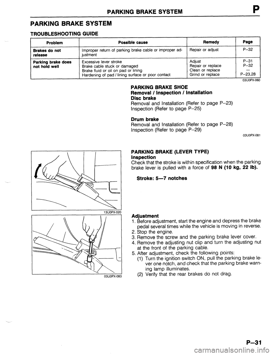
PARKING BRAKE (LEVER TYPE)
Inspection
Check that the stroke is within specification when the parking
brake lever is pulled with a force of 98 N (IO
kg, 22 lb).
Stroke: 5-7 notches
Adjustment
1. Before adjustment, start the engine and depress the brake
pedal several times while the vehicle is moving in reverse.
2. Stop the engine.
3. Remove the screw and the parking brake lever cover.
4. Remove the adjusting nut clip and turn the adjusting nut
at the front of the parking cable.
5. After adjustment, check the following points:
(1) Turn the ignition switch ON, pull the parking brake le
ver one notch, and check that the parking brake warn-
ing lamp illuminates.
(2) Verify that the rear brakes do not drag.
P-31
Page 917 of 1164

WARNING SYSTEM T
13UOTX-07
63U15X-05
, I//
‘nF -
-
-
FUEL
13UOTX.08C
- CHARGE
13UOTX-08
13UOTX-08
Inspection
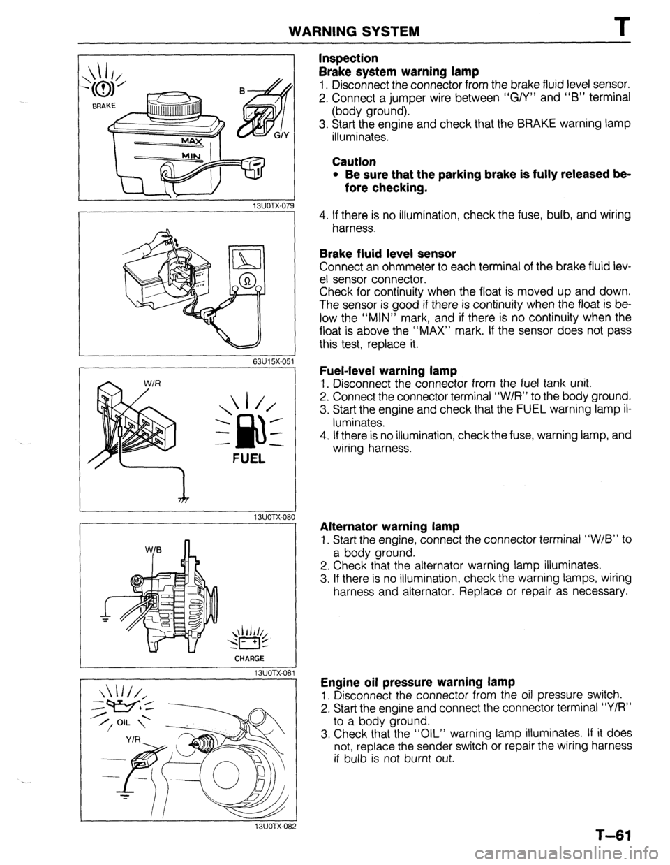
Brake system warning lamp
1. Disconnect the connector from the brake fluid level sensor.
2. Connect a jumper wire between “G/Y” and “6” terminal
(body ground).
3. Start the engine and check that the BRAKE warning lamp
illuminates.
Caution
l Be sure that the parking brake is fully released be-
fore checking.
4. If there is no illumination, check the fuse, bulb, and wiring
harness.
Brake fluid level sensor
Connect an ohmmeter to each terminal of the brake fluid lev-
el sensor connector.
Check for continuity when the float is moved up and down.
The sensor is good if there is continuity when the float is be-
low the “MIN” mark, and if there is no continuity when the
float is above the “MAX” mark. If the sensor does not pass
this test, replace it.
Fuel-level warning lamp
1. Disconnect the connector from the fuel tank unit.
2. Connect the connector terminal “W/R” to the body ground.
3. Start the engine and check that the FUEL warning lamp il-
luminates.
4. If there is no illumination, check the fuse, warning lamp, and
wiring harness.
Alternator warning lamp
1. Start the engine, connect the connector terminal “W/B” to
a body ground.
2. Check that the alternator warning lamp illuminates.
3. If there is no illumination, check the warning lamps, wiring
harness and alternator. Replace or repair as necessary.
Engine oil pressure warning lamp
1. Disconnect the connector from the oil pressure switch.
2. Start the engine and connect the connector terminal “Y/R”
to a body ground.
3. Check that the “OIL” warning lamp illuminates. If it does
not, replace the sender switch or repair the wiring harness
if bulb is not burnt out.
T-61