1988 OPEL VECTRA cooling
[x] Cancel search: coolingPage 52 of 525
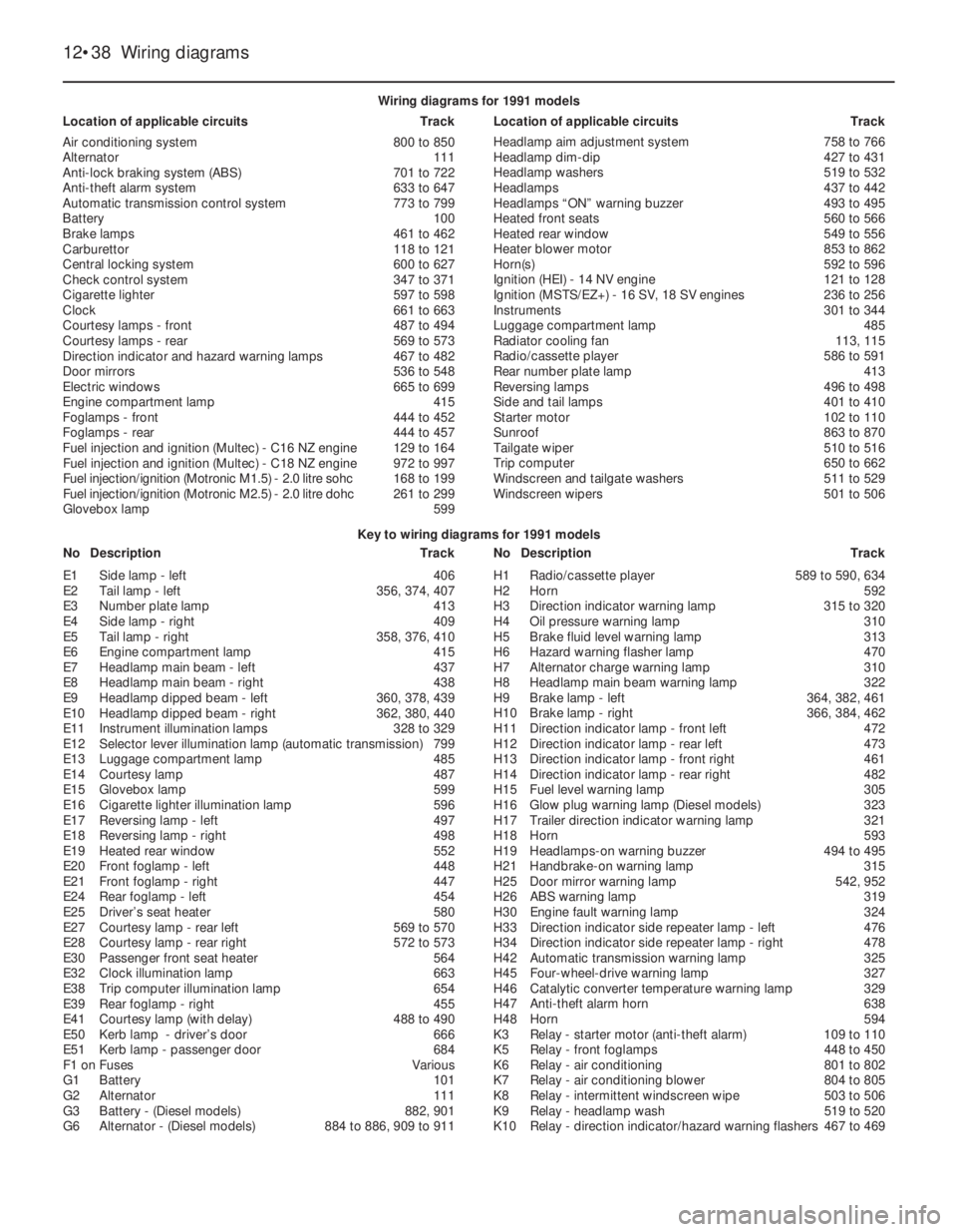
12•38Wiring diagrams
Key to wiring diagrams for 1991 models
NoDescriptionTrackNoDescriptionTrack Wiring diagrams for 1991 models
Location of applicable circuitsTrackLocation of applicable circuitsTrack
Air conditioning system800 to 850
Alternator111
Anti-lock braking system (ABS)701 to 722
Anti-theft alarm system633 to 647
Automatic transmission control system773 to 799
Battery100
Brake lamps461 to 462
Carburettor118 to 121
Central locking system600 to 627
Check control system347 to 371
Cigarette lighter597 to 598
Clock661 to 663
Courtesy lamps - front487 to 494
Courtesy lamps - rear569 to 573
Direction indicator and hazard warning lamps467 to 482
Door mirrors536 to 548
Electric windows665 to 699
Engine compartment lamp415
Foglamps - front444 to 452
Foglamps - rear444 to 457
Fuel injection and ignition (Multec) - C16NZ engine129 to 164
Fuel injection and ignition (Multec) - C18NZ engine972 to 997
Fuel injection/ignition (Motronic M1.5) - 2.0litre sohc 168 to 199
Fuel injection/ignition (Motronic M2.5) - 2.0litre dohc 261 to 299
Glovebox lamp599Headlamp aim adjustment system758 to 766
Headlamp dim-dip427 to 431
Headlamp washers519 to 532
Headlamps437 to 442
Headlamps “ON” warning buzzer493 to 495
Heated front seats560 to 566
Heated rear window549 to 556
Heater blower motor853 to 862
Horn(s)592 to 596
Ignition (HEI) - 14NV engine121 to 128
Ignition (MSTS/EZ+) - 16SV, 18 SV engines236 to 256
Instruments301 to 344
Luggage compartment lamp485
Radiator cooling fan113, 115
Radio/cassette player586 to 591
Rear number plate lamp413
Reversing lamps496 to 498
Side and tail lamps401 to 410
Starter motor102 to 110
Sunroof863 to 870
Tailgate wiper510 to 516
Trip computer650 to 662
Windscreen and tailgate washers511 to 529
Windscreen wipers501 to 506
E1Side lamp - left406
E2Tail lamp - left356, 374, 407
E3Number plate lamp413
E4Side lamp - right409
E5Tail lamp - right358, 376, 410
E6Engine compartment lamp415
E7Headlamp main beam - left437
E8Headlamp main beam - right438
E9Headlamp dipped beam - left360, 378, 439
E10Headlamp dipped beam - right362, 380, 440
E11Instrument illumination lamps328 to 329
E12Selector lever illumination lamp (automatic transmission)799
E13Luggage compartment lamp485
E14Courtesy lamp487
E15Glovebox lamp599
E16Cigarette lighter illumination lamp596
E17Reversing lamp - left497
E18Reversing lamp - right498
E19Heated rear window552
E20Front foglamp - left448
E21Front foglamp - right447
E24Rear foglamp - left454
E25Driver’s seat heater580
E27Courtesy lamp - rear left569 to 570
E28Courtesy lamp - rear right572 to 573
E30Passenger front seat heater564
E32Clock illumination lamp663
E38Trip computer illumination lamp654
E39Rear foglamp - right455
E41Courtesy lamp (with delay)488 to 490
E50Kerb lamp - driver’s door666
E51Kerb lamp - passenger door684
F1 onFusesVarious
G1Battery101
G2Alternator111
G3Battery - (Diesel models)882, 901
G6Alternator - (Diesel models)884 to 886, 909 to 911H1Radio/cassette player589 to 590, 634
H2Horn592
H3Direction indicator warning lamp315 to 320
H4Oil pressure warning lamp310
H5Brake fluid level warning lamp313
H6Hazard warning flasher lamp470
H7Alternator charge warning lamp310
H8Headlamp main beam warning lamp322
H9Brake lamp - left364, 382, 461
H10Brake lamp - right366, 384, 462
H11Direction indicator lamp - front left472
H12Direction indicator lamp - rear left473
H13Direction indicator lamp - front right461
H14Direction indicator lamp - rear right482
H15Fuel level warning lamp305
H16Glow plug warning lamp (Diesel models)323
H17Trailer direction indicator warning lamp321
H18Horn593
H19Headlamps-on warning buzzer494 to 495
H21Handbrake-on warning lamp315
H25Door mirror warning lamp542, 952
H26ABS warning lamp319
H30Engine fault warning lamp324
H33Direction indicator side repeater lamp - left476
H34Direction indicator side repeater lamp - right478
H42Automatic transmission warning lamp325
H45Four-wheel-drive warning lamp327
H46Catalytic converter temperature warning lamp329
H47Anti-theft alarm horn638
H48Horn594
K3Relay - starter motor (anti-theft alarm)109 to 110
K5Relay - front foglamps448 to 450
K6Relay - air conditioning801 to 802
K7Relay - air conditioning blower804 to 805
K8Relay - intermittent windscreen wipe503 to 506
K9Relay - headlamp wash519 to 520
K10Relay - direction indicator/hazard warning flashers467 to 469
Page 53 of 525
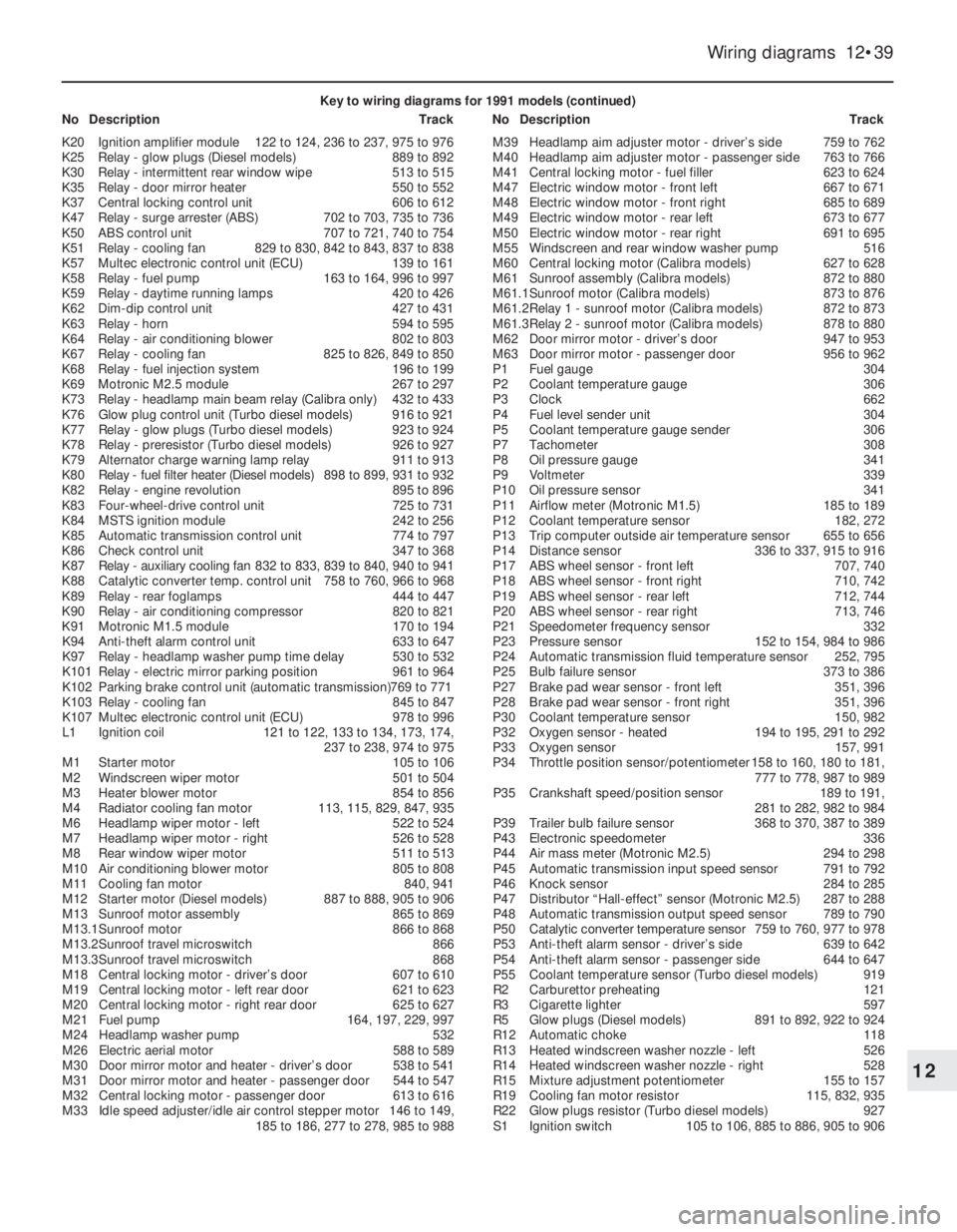
Wiring diagrams 12•39
12
Key to wiring diagrams for 1991 models (continued)
NoDescriptionTrackNoDescriptionTrack
K20Ignition amplifier module122 to 124, 236 to 237, 975 to 976
K25Relay - glow plugs (Diesel models)889 to 892
K30Relay - intermittent rear window wipe513 to 515
K35Relay - door mirror heater550 to 552
K37Central locking control unit606 to 612
K47Relay - surge arrester (ABS)702 to 703, 735 to 736
K50ABS control unit707 to 721, 740 to 754
K51Relay - cooling fan829 to 830, 842 to 843, 837 to 838
K57Multec electronic control unit (ECU)139 to 161
K58Relay - fuel pump163 to 164, 996 to 997
K59Relay - daytime running lamps420 to 426
K62Dim-dip control unit427 to 431
K63Relay - horn594 to 595
K64Relay - air conditioning blower802 to 803
K67Relay - cooling fan825 to 826, 849 to 850
K68Relay - fuel injection system196 to 199
K69Motronic M2.5 module267 to 297
K73Relay - headlamp main beam relay (Calibra only)432 to 433
K76Glow plug control unit (Turbo diesel models)916 to 921
K77Relay - glow plugs (Turbo diesel models)923 to 924
K78Relay - preresistor (Turbo diesel models)926 to 927
K79Alternator charge warning lamp relay911 to 913
K80Relay - fuel filter heater (Diesel models)898 to 899, 931 to 932
K82Relay - engine revolution895 to 896
K83Four-wheel-drive control unit725 to 731
K84MSTS ignition module242 to 256
K85Automatic transmission control unit774 to 797
K86Check control unit347 to 368
K87Relay - auxiliary cooling fan832 to 833, 839 to 840, 940 to 941
K88Catalytic converter temp. control unit758 to 760, 966 to 968
K89Relay - rear foglamps444 to 447
K90Relay - air conditioning compressor820 to 821
K91Motronic M1.5 module170 to 194
K94Anti-theft alarm control unit633 to 647
K97Relay - headlamp washer pump time delay530 to 532
K101Relay - electric mirror parking position961 to 964
K102Parking brake control unit (automatic transmission)769 to 771
K103Relay - cooling fan845 to 847
K107Multec electronic control unit (ECU)978 to 996
L1Ignition coil121 to 122, 133 to 134, 173, 174,
237 to 238, 974 to 975
M1Starter motor105 to 106
M2Windscreen wiper motor501 to 504
M3Heater blower motor854 to 856
M4Radiator cooling fan motor113, 115, 829, 847, 935
M6Headlamp wiper motor - left522 to 524
M7Headlamp wiper motor - right526 to 528
M8Rear window wiper motor511 to 513
M10Air conditioning blower motor805 to 808
M11Cooling fan motor840, 941
M12Starter motor (Diesel models)887 to 888, 905 to 906
M13Sunroof motor assembly865 to 869
M13.1Sunroof motor866 to 868
M13.2Sunroof travel microswitch866
M13.3Sunroof travel microswitch868
M18Central locking motor - driver’s door607 to 610
M19Central locking motor - left rear door621 to 623
M20Central locking motor - right rear door625 to 627
M21Fuel pump164, 197, 229, 997
M24Headlamp washer pump532
M26Electric aerial motor588 to 589
M30Door mirror motor and heater - driver’s door538 to 541
M31Door mirror motor and heater - passenger door544 to 547
M32Central locking motor - passenger door613 to 616
M33Idle speed adjuster/idle air control stepper motor146 to 149,
185 to 186, 277 to 278, 985 to 988M39Headlamp aim adjuster motor - driver’s side759 to 762
M40Headlamp aim adjuster motor - passenger side763 to 766
M41Central locking motor - fuel filler623 to 624
M47Electric window motor - front left667 to 671
M48Electric window motor - front right685 to 689
M49Electric window motor - rear left673 to 677
M50Electric window motor - rear right691 to 695
M55Windscreen and rear window washer pump516
M60Central locking motor (Calibra models)627 to 628
M61Sunroof assembly (Calibra models)872 to 880
M61.1Sunroof motor (Calibra models)873 to 876
M61.2Relay 1 - sunroof motor (Calibra models)872 to 873
M61.3Relay 2 - sunroof motor (Calibra models)878 to 880
M62Door mirror motor - driver’s door947 to 953
M63Door mirror motor - passenger door956 to 962
P1Fuel gauge304
P2Coolant temperature gauge306
P3Clock662
P4Fuel level sender unit304
P5Coolant temperature gauge sender306
P7Tachometer308
P8Oil pressure gauge341
P9Voltmeter339
P10Oil pressure sensor341
P11Airflow meter (Motronic M1.5)185 to 189
P12Coolant temperature sensor182, 272
P13Trip computer outside air temperature sensor655 to 656
P14Distance sensor336 to 337, 915 to 916
P17ABS wheel sensor - front left707, 740
P18ABS wheel sensor - front right710, 742
P19ABS wheel sensor - rear left712, 744
P20ABS wheel sensor - rear right713, 746
P21Speedometer frequency sensor332
P23Pressure sensor152 to 154, 984 to 986
P24Automatic transmission fluid temperature sensor252, 795
P25Bulb failure sensor373 to 386
P27Brake pad wear sensor - front left351, 396
P28Brake pad wear sensor - front right351, 396
P30Coolant temperature sensor150, 982
P32Oxygen sensor - heated194 to 195, 291 to 292
P33Oxygen sensor157, 991
P34Throttle position sensor/potentiometer158 to 160, 180 to 181,
777 to 778, 987 to 989
P35Crankshaft speed/position sensor189 to 191,
281 to 282, 982 to 984
P39Trailer bulb failure sensor368 to 370, 387 to 389
P43Electronic speedometer336
P44Air mass meter (Motronic M2.5)294 to 298
P45Automatic transmission input speed sensor791 to 792
P46Knock sensor284 to 285
P47Distributor “Hall-effect” sensor (Motronic M2.5)287 to 288
P48Automatic transmission output speed sensor789 to 790
P50Catalytic converter temperature sensor759 to 760, 977 to 978
P53Anti-theft alarm sensor - driver’s side639 to 642
P54Anti-theft alarm sensor - passenger side644 to 647
P55Coolant temperature sensor (Turbo diesel models)919
R2Carburettor preheating121
R3Cigarette lighter597
R5Glow plugs (Diesel models)891 to 892, 922 to 924
R12Automatic choke118
R13Heated windscreen washer nozzle - left526
R14Heated windscreen washer nozzle - right528
R15Mixture adjustment potentiometer155 to 157
R19Cooling fan motor resistor115, 832, 935
R22Glow plugs resistor (Turbo diesel models)927
S1Ignition switch105 to 106, 885 to 886, 905 to 906
Page 54 of 525
12•40Wiring diagrams
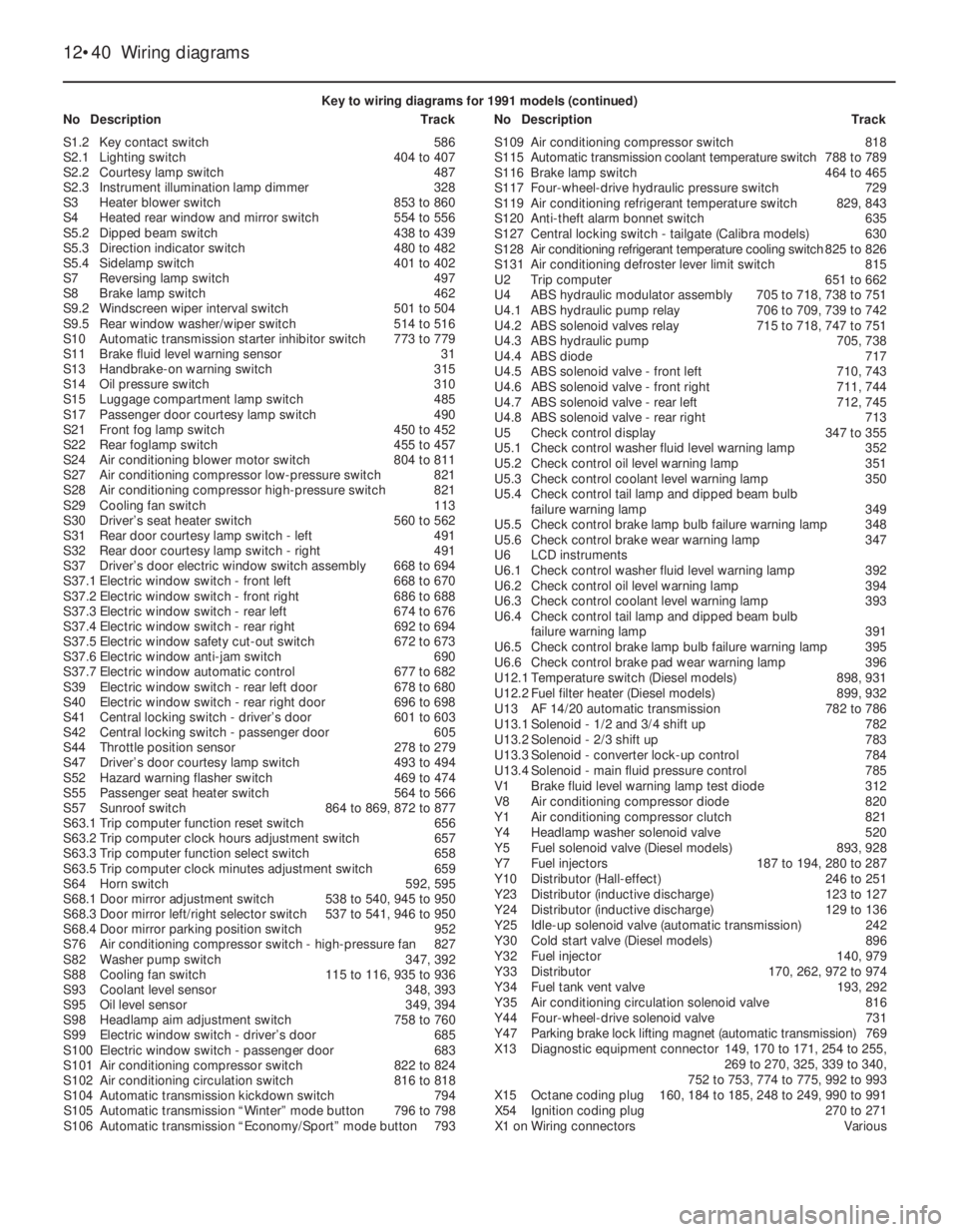
Key to wiring diagrams for 1991 models (continued)
NoDescriptionTrackNoDescriptionTrack
S1.2Key contact switch586
S2.1Lighting switch404 to 407
S2.2Courtesy lamp switch487
S2.3Instrument illumination lamp dimmer328
S3Heater blower switch853 to 860
S4Heated rear window and mirror switch554 to 556
S5.2Dipped beam switch438 to 439
S5.3Direction indicator switch480 to 482
S5.4Sidelamp switch401 to 402
S7Reversing lamp switch497
S8Brake lamp switch462
S9.2Windscreen wiper interval switch501 to 504
S9.5Rear window washer/wiper switch514 to 516
S10Automatic transmission starter inhibitor switch773 to 779
S11Brake fluid level warning sensor31
S13Handbrake-on warning switch315
S14Oil pressure switch310
S15Luggage compartment lamp switch485
S17Passenger door courtesy lamp switch490
S21Front fog lamp switch450 to 452
S22Rear foglamp switch455 to 457
S24Air conditioning blower motor switch804 to 811
S27Air conditioning compressor low-pressure switch821
S28Air conditioning compressor high-pressure switch821
S29Cooling fan switch113
S30Driver’s seat heater switch560 to 562
S31Rear door courtesy lamp switch - left491
S32Rear door courtesy lamp switch - right491
S37Driver’s door electric window switch assembly668 to 694
S37.1Electric window switch - front left668 to 670
S37.2Electric window switch - front right686 to 688
S37.3Electric window switch - rear left674 to 676
S37.4Electric window switch - rear right692 to 694
S37.5Electric window safety cut-out switch672 to 673
S37.6Electric window anti-jam switch690
S37.7Electric window automatic control677 to 682
S39Electric window switch - rear left door678 to 680
S40Electric window switch - rear right door696 to 698
S41Central locking switch - driver’s door601 to 603
S42Central locking switch - passenger door605
S44Throttle position sensor278 to 279
S47Driver’s door courtesy lamp switch493 to 494
S52Hazard warning flasher switch469 to 474
S55Passenger seat heater switch564 to 566
S57Sunroof switch864 to 869, 872 to 877
S63.1Trip computer function reset switch656
S63.2Trip computer clock hours adjustment switch657
S63.3Trip computer function select switch658
S63.5Trip computer clock minutes adjustment switch659
S64Horn switch592, 595
S68.1Door mirror adjustment switch538 to 540, 945 to 950
S68.3Door mirror left/right selector switch537 to 541, 946 to 950
S68.4Door mirror parking position switch952
S76Air conditioning compressor switch - high-pressure fan827
S82Washer pump switch347, 392
S88Cooling fan switch115 to 116, 935 to 936
S93Coolant level sensor348, 393
S95Oil level sensor349, 394
S98Headlamp aim adjustment switch758 to 760
S99Electric window switch - driver’s door685
S100Electric window switch - passenger door683
S101Air conditioning compressor switch822 to 824
S102Air conditioning circulation switch816 to 818
S104Automatic transmission kickdown switch794
S105Automatic transmission “Winter” mode button796 to 798
S106Automatic transmission “Economy/Sport” mode button793S109Air conditioning compressor switch818
S115Automatic transmission coolant temperature switch788 to 789
S116Brake lamp switch464 to 465
S117Four-wheel-drive hydraulic pressure switch729
S119Air conditioning refrigerant temperature switch829, 843
S120Anti-theft alarm bonnet switch635
S127Central locking switch - tailgate (Calibra models)630
S128Air conditioning refrigerant temperature cooling switch825 to 826
S131Air conditioning defroster lever limit switch815
U2Trip computer651 to 662
U4ABS hydraulic modulator assembly705 to 718, 738 to 751
U4.1ABS hydraulic pump relay706 to 709, 739 to 742
U4.2ABS solenoid valves relay715 to 718, 747 to 751
U4.3ABS hydraulic pump705, 738
U4.4ABS diode717
U4.5ABS solenoid valve - front left710, 743
U4.6ABS solenoid valve - front right711, 744
U4.7ABS solenoid valve - rear left712, 745
U4.8ABS solenoid valve - rear right713
U5Check control display347 to 355
U5.1Check control washer fluid level warning lamp352
U5.2Check control oil level warning lamp351
U5.3Check control coolant level warning lamp350
U5.4Check control tail lamp and dipped beam bulb
failure warning lamp349
U5.5Check control brake lamp bulb failure warning lamp348
U5.6Check control brake wear warning lamp347
U6LCD instruments
U6.1Check control washer fluid level warning lamp392
U6.2Check control oil level warning lamp394
U6.3Check control coolant level warning lamp393
U6.4Check control tail lamp and dipped beam bulb
failure warning lamp391
U6.5Check control brake lamp bulb failure warning lamp395
U6.6Check control brake pad wear warning lamp396
U12.1Temperature switch (Diesel models)898, 931
U12.2Fuel filter heater (Diesel models)899, 932
U13AF14/20automatic transmission782 to 786
U13.1Solenoid - 1/2 and 3/4 shift up782
U13.2Solenoid - 2/3 shift up783
U13.3Solenoid - converter lock-up control784
U13.4Solenoid - main fluid pressure control785
V1Brake fluid level warning lamp test diode312
V8Air conditioning compressor diode820
Y1Air conditioning compressor clutch821
Y4Headlamp washer solenoid valve520
Y5Fuel solenoid valve (Diesel models)893, 928
Y7Fuel injectors187 to 194, 280 to 287
Y10Distributor (Hall-effect)246 to 251
Y23Distributor (inductive discharge)123 to 127
Y24Distributor (inductive discharge)129 to 136
Y25Idle-up solenoid valve (automatic transmission)242
Y30Cold start valve (Diesel models)896
Y32Fuel injector140, 979
Y33Distributor170, 262, 972 to 974
Y34Fuel tank vent valve193, 292
Y35Air conditioning circulation solenoid valve816
Y44Four-wheel-drive solenoid valve731
Y47Parking brake lock lifting magnet (automatic transmission)769
X13Diagnostic equipment connector149, 170 to 171, 254 to 255,
269 to 270, 325, 339 to 340,
752 to 753, 774 to 775, 992 to 993
X15Octane coding plug160, 184 to 185, 248 to 249, 990 to 991
X54Ignition coding plug270 to 271
X1 onWiring connectorsVarious
Page 92 of 525
5If the engine turns over at normal speed but
will not start, check the HT circuit by
connecting a timing light and turning the
engine over on the starter motor. If the light
flashes, voltage is reaching the spark plugs,
so these should be checked first. If the light
does not flash, check the HT leads
themselves followed by the distributor cap,
carbon brush and rotor arm.
6If there is a spark, check the fuel system for
faults as far as possible (Chapters 4A or 4B).
7If there is still no spark, check the voltage at
the ignition coil “+” or “15” terminal; it should
be the same as the battery voltage (i.e., at
least 11.7 volts). If the voltage at the coil is
more than 1 volt less than that at the battery,
check the connections back through the
ignition switch to the battery and its earth until
the fault is found. Note, however, that the
ECU controls the coil’s feed; do not attempt
to “test” the ECU with anything other than the
correct test equipment, which will be available
only to a Vauxhall dealer. If any of the wires
are to be checked which lead to the ECU,
always first unplug the relevant connector
from the ECU so that there is no risk of the
ECU being damaged by the application of
incorrect voltages from test equipment.
8If the feed to the ignition coil is sound,
check the coil’s primary and secondary
windings (refer to Section 16). Renew the coil
if faulty, but check the condition of the LT
connections themselves before doing so, to
ensure that the fault is not due to dirty or
poorly fastened connectors.
9If the ignition coil is in good condition, the
fault may be within the amplifier module or the
distributor on the C16 NZ and C16 NZ2
engines, or the amplifier or the crankshaft
speed/position sensor on the C18 NZ engine.
A quick check of these components can be
made by connecting a low-wattage bulb
across the ignition coil’s (disconnected) LT
terminals. If the bulb flickers or flashes when
the engine is turned over, the amplifier and
distributor (C16 NZ and C16 NZ2 engines), or
amplifier and crankshaft speed/position
sensor (C18 NZ engine), are sound.
10If this is the case, the entire LT circuit is in
good condition; the fault, if it lies in the
ignition system, must be in the HT circuit
components. These should be checked
carefully, as outlined above.
11If the indicator or bulb does not flash, the
fault is in either the amplifier or the distributor
(C16 NZ and C16 NZ2 engines), or the
amplifier or crankshaft speed/position sensor
(C18 NZ engine). Owners should note,
however, that by far the commonest cause of
“failure” of either of these is a poor
connection, either between the components
themselves or in the LT circuit wiring
connections. If such a fault is suspected, the
vehicle must be taken to a suitably equipped
Vauxhall dealer for testing; no information is
available to eliminate these components by
other means.12An irregular misfire suggests either a
loose connection or intermittent fault on the
primary circuit, or a HT fault on the coil side of
the rotor arm.
13With the ignition switched off, check
carefully through the system ensuring that all
connections are clean and securely fastened.
If the equipment is available, check the LT
circuit as described in paragraphs 7 to 11
above.
14Check that the HT coil, the distributor cap
and the HT leads are clean and dry. Check the
leads and the spark plugs (by substitution, if
necessary), then check the distributor cap,
carbon brush and rotor arm.
15Regular misfiring is almost certainly due to
a fault in the distributor cap, HT leads or spark
plugs. Use a timing light (paragraph 5, above)
to check whether HT voltage is present at all
leads.
16If HT voltage is not present on any
particular lead, the fault will be in that lead or
in the distributor cap. If HT is present on all
leads, the fault will be in the spark plugs;
check and renew them if there is any doubt
about their condition.
17If no HT voltage is present, check the
ignition coil; its secondary windings may be
breaking down under load.
18If all components have been checked for
signs of obvious faults but the system is still
thought to be faulty, take the vehicle to a
Vauxhall dealer for testing on special
equipment.
5Battery - testing and charging
2
Note: Refer to Section 3 before proceeding.
Testing
1Topping-up and testing of the electrolyte in
each cell is not possible. The condition of the
battery can therefore only be tested by
observing the battery condition indicator.
2The battery condition indicator is fitted in
the top of the battery casing, and indicates
the condition of the battery from its colour. If
the indicator shows green, then the battery is
in a good state of charge. If the indicator turns
darker, eventually to black, then the battery
requires charging, as described later in this
Section. If the indicator shows clear/yellow,
then the electrolyte level in the battery is too
low to allow further use, and the battery
should be renewed.
Charging
3Do not attempt to charge, load or jump start
a battery when the indicator shows
clear/yellow. If the battery is to be charged,
remove it from the vehicle and charge it as
follows.
4The maintenance-free type battery takes
considerably longer to fully recharge than the
standard type, the time taken being
dependent on the extent of discharge.5A constant-voltage type charger is required,
to be set, when connected, to 13.9 to 14.9
volts with a charger current below 25 amps.
6If the battery is to be charged from a fully
discharged state (less than 12.2 volts output),
have it recharged by a Vauxhall dealer or
battery specialist, as the charge rate will be
high and constant supervision during charging
is necessary.
6Battery - removal and refitting
2
Note: Refer to Section 3 before proceeding.
Removal
1The battery is located at the left-hand front
corner of the engine compartment.
2Disconnect the lead(s) at the negative
(earth) terminal by unscrewing the retaining
nut and removing the terminal clamp.
3Disconnect the positive terminal lead(s) in
the same way.
4Unscrew the clamp bolt sufficiently to
enable the battery to be lifted from its
location. Keep the battery in an upright
position, to avoid spilling electrolyte on the
bodywork.
Refitting
5Refitting is a reversal of removal, but smear
petroleum jelly on the terminals when
reconnecting the leads, and always connect
the positive lead first and the negative lead
last.
7Alternator - description
1A Delco-Remy or Bosch alternator may be
fitted, depending on model and engine
capacity. The maximum output of the
alternator varies accordingly.
2The alternator is belt-driven from the
crankshaft pulley. Cooling is provided by a
fan, mounted outside the casing on the end of
the rotor shaft. An integral voltage regulator is
incorporated, to control the output voltage.
3The alternator provides a charge to the
battery even at very low engine speed, and
consists of a coil-wound stator in which a
rotor rotates. The rotor shaft is supported in
ball-bearings, and slip rings are used to
conduct current to and from the field coils
through the carbon brushes.
4The alternator generates ac (alternating
current), which is rectified by an internal diode
circuit to dc (direct current) for supply to the
battery.
5Later models are fitted with a Delco-Remy,
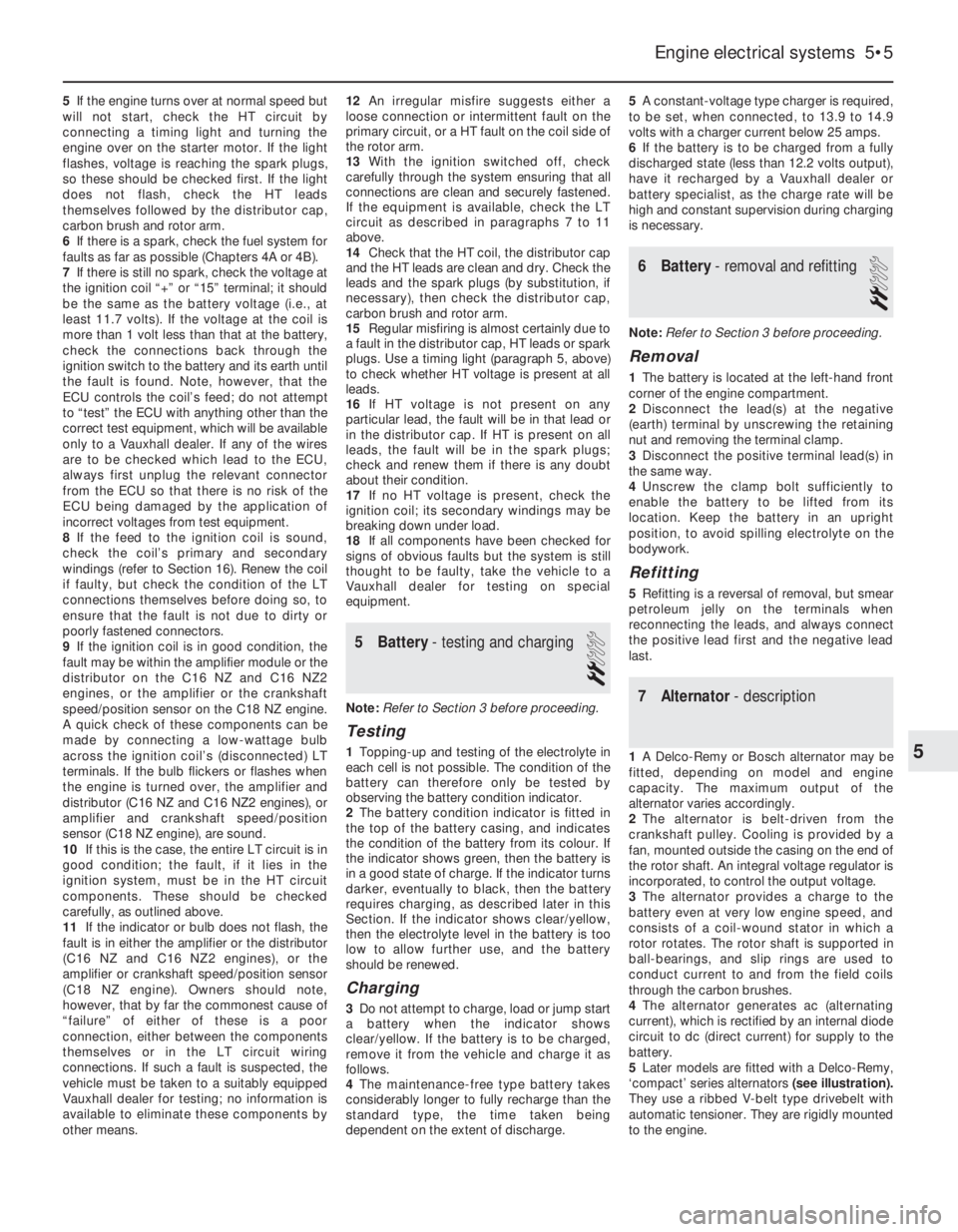
‘compact’ series alternators (see illustration).
They use a ribbed V-belt type drivebelt with
automatic tensioner. They are rigidly mounted
to the engine.
Engine electrical systems 5•5
5
Page 100 of 525
Inspection
17Examine the distributor cap and rotor arm,
as described in paragraphs 6 and 7. Examine
the O-rings at the rear of the distributor body,
and on the rear of the shaft, and renew if
necessary.
Reassembly
18Reassembly is a reversal of dismantling,
ensuring that the thrustwashers are correctly
located. Note that the drive collar should be
refitted so that the drive peg on the collar is
aligned with the groove in the top of the
distributor shaft (it is possible to fit the drive
collar 180°out of position).
19Refit the distributor as described in
Section 18, and then check and if necessary
adjust the ignition timing, as described in
Section 21.
DOHC models (where
applicable)
20The distributor cap and rotor arm can be
examined as described in paragraphs 6 and 7.
21Ignition timing -checking and
adjustment
4
Note: Refer to Section 3 before proceeding. A
tachometer and a timing light will be required
during this procedure. For details of ignition
timing adjustment required to operate vehicles
on unleaded petrol, refer to Section 22.
14 NV and 16 SV models
Checking
1Start the engine and run it until it reaches
normal operating temperature, then switch
off.
2On 14 NV models, disconnect the vacuum
pipe from the distributor vacuum diaphragm
unit.
3On all models use a spanner applied to the
crankshaft pulley bolt to rotate the crankshaft
clockwise until the notch in the pulley’s
inboard rim aligns with the pointer protruding
from the oil pump housing. On 14 NV models,
where two notches (indicating 10°and 5°
BTDC respectively) are found, rotate the
crankshaft until the second notch (in thedirection of rotation -i.e. 5°BTDC) aligns. Use
white paint or similar to emphasise the pointer
and notch, to make them easier to see.
4Connect a timing light to No 1 cylinder
(nearest the timing belt end of the engine) HT
lead, also a tachometer; follow the equipment
manufacturer’s instructions for connection.
5Start the engine and allow it to idle -the
speed should be between 700 and 1000 rpm.
6On 14 NV models, aim the timing light at the
pointer and check that it is aligned with the
crankshaft pulley notch.
7On early 16 SV models, disconnect the
ignition timing basic adjustment coding plug.
This can be identified by a length of Black
wire joining Brown/Red and Brown/Yellow
wires in a connector plug clipped to the wiring
or heater/cooling system hoses beneath the
battery/ignition coil (see illustration, 16.1). This
causes the MSTS-i module to adopt its basic
adjustment mode, sending a constant firing
signal corresponding to 10°BTDC and
eliminating any advance below 2000 rpm. Aim
the timing light at the pointer and check that it
is aligned with the crankshaft pulley notch.
8On later 16 SV, C 16 NZ and C 16 NZ2
models, the coding plugs are no longer fitted.
For accurate checking, special Vauxhall test
equipment must be used which causes the
MSTS module to adopt its basic adjustment
mode.
9Without access to such equipment, it is
possible to check and adjust the ignition
timing, accurate results cannot be
guaranteed. Owners are therefore advised to
have this work carried out by a suitably
equipped Vauxhall dealer; at the very least,
make the initial setting yourself and then have
it checked as soon as possible.
10If you do attempt to check the ignition
timing yourself, note that the fixed reference
mark is now an extended line embossed on
the timing belt lower outer cover.
Adjustment
11If the notch and pointer are not aligned,
loosen the distributor clamp nut and turn the
distributor body slightly in the required
direction to align.
12Tighten the distributor clamp nut, and
check that the notch and pointer are still
aligned. 13Stop the engine, and disconnect the
timing light and tachometer.
14On 16 SV models, reconnect the basic
adjustment coding plug. On 14 NV models,
reconnect the vacuum pipe to the distributor
vacuum diaphragm unit.
Other models
15No adjustment of the ignition timing is
possible on 1.8 and 2.0 litre models, as the
adjustment is carried out automatically by the
electronic control module.
16The ignition timing can be checked by a
Vauxhall dealer using specialist dedicated test
equipment, if a fault is suspected.
22Ignition timing -adjustment
for use with unleaded petrol
3
14 NV models
1All models with the 14 NV engine have the
ignition timing adjusted for use with 95 RON
unleaded petrol before they leave the factory,
and no further adjustment is required.
2Leaded petrol (98 RON) can be used if
desired, with no adverse effects.
1.6, 1.8 and 2.0 SOHC models
Note: Models equipped with a catalytic
converter must be operated on 95 R0N
unleaded petrol at all times, and although an
octane coding plug may be fitted, it should
not be tampered with
3Models, other than 14 NV, are equipped
with an octane coding plug, which is located
Engine electrical systems 5•13
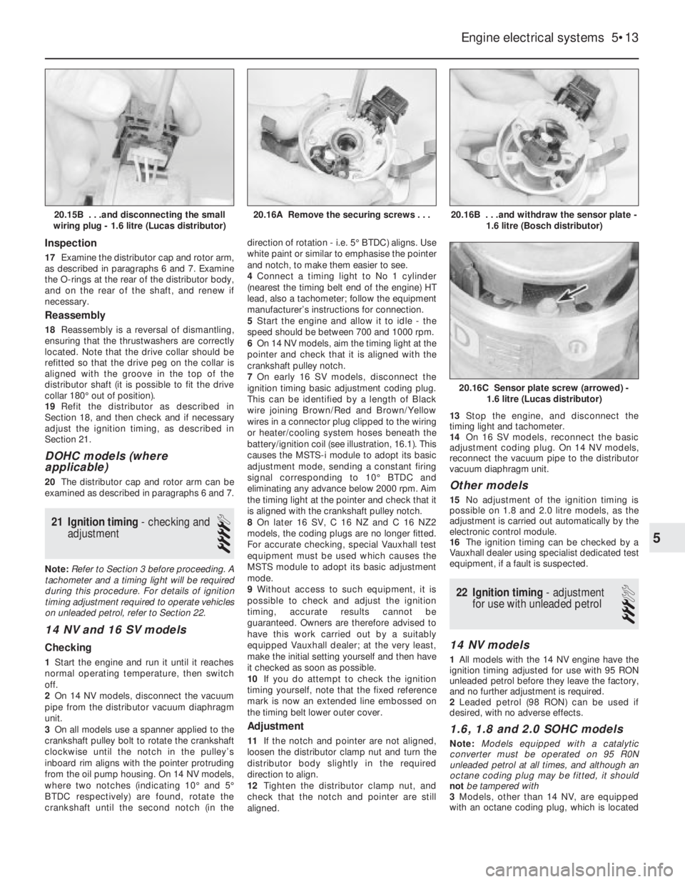
20.16B . . .and withdraw the sensor plate -
1.6 litre (Bosch distributor)
20.16C Sensor plate screw (arrowed) -
1.6 litre (Lucas distributor)
20.16A Remove the securing screws . . .20.15B . . .and disconnecting the small
wiring plug - 1.6 litre (Lucas distributor)
5
Page 102 of 525
3Lift up the edge of the windscreen cowl
panel for access to the sensor.
4Disconnect the sensor wiring plug, and the
vacuum pipe.
5Pull the pressure sensor upwards to release
it from its bracket, and withdraw it from the
vehicle.
Refitting
6Refitting is a reversal of removal. However,
on Multec models no fuel vapour trap is fitted.
It is therefore essential that the sensor
vacuum hose is routed so that it falls steadily
from the sensor to the throttle body. This
precaution prevents any fuel droplets being
trapped in the sensor or hose, and allows
them to drain into the inlet port.
Oil temperature sensor
Removal
7The sensor is screwed into the inlet
manifold side of the cylinder block, next to the
starter motor’s right-hand end.
8The sensor can be reached quite easily
from above, but if it is to be removed from
beneath, ensure that the handbrake is
applied, and that the vehicle is securely
supported on axle stands (see “Jacking and
Vehicle Support”).
9Disconnect the battery negative lead.
10Disconnect the sensor wiring plug.
11Using a spanner, unscrew the sensor and
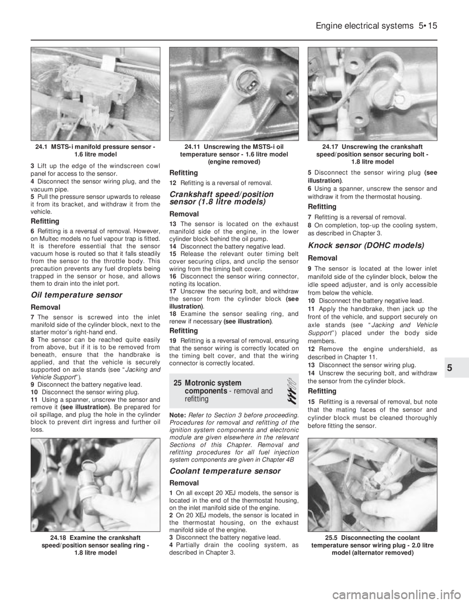
remove it (see illustration). Be prepared for
oil spillage, and plug the hole in the cylinder
block to prevent dirt ingress and further oil
loss.
Refitting
12Refitting is a reversal of removal.
Crankshaft speed/position
sensor (1.8 litre models)
Removal
13The sensor is located on the exhaust
manifold side of the engine, in the lower
cylinder block behind the oil pump.
14Disconnect the battery negative lead.
15Release the relevant outer timing belt
cover securing clips, and unclip the sensor
wiring from the timing belt cover.
16Disconnect the sensor wiring connector,
noting its location.
17Unscrew the securing bolt, and withdraw
the sensor from the cylinder block (see
illustration).
18Examine the sensor sealing ring, and
renew if necessary (see illustration).
Refitting
19Refitting is a reversal of removal, ensuring
that the sensor wiring is correctly located on
the timing belt cover, and that the wiring
connector is correctly located.
25Motronic system
components - removal and
refitting
3
Note: Refer to Section 3 before proceeding.
Procedures for removal and refitting of the
ignition system components and electronic
module are given elsewhere in the relevant
Sections of this Chapter. Removal and
refitting procedures for all fuel injection
system components are given in Chapter 4B
Coolant temperature sensor
Removal
1On all except 20 XEJ models, the sensor is
located in the end of the thermostat housing,
on the inlet manifold side of the engine.
2On 20 XEJ models, the sensor is located in
the thermostat housing, on the exhaust
manifold side of the engine.
3Disconnect the battery negative lead.
4Partially drain the cooling system, as
described in Chapter 3. 5Disconnect the sensor wiring plug (see
illustration).
6Using a spanner, unscrew the sensor and
withdraw it from the thermostat housing.
Refitting
7Refitting is a reversal of removal.
8On completion, top-up the cooling system,
as described in Chapter 3.
Knock sensor (DOHC models)
Removal
9The sensor is located at the lower inlet
manifold side of the cylinder block, below the
idle speed adjuster, and is only accessible
from below the vehicle.
10Disconnect the battery negative lead.
11Apply the handbrake, then jack up the
front of the vehicle, and support securely on
axle stands (see “Jacking and Vehicle
Support”) placed under the body side
members.
12Remove the engine undershield, as
described in Chapter 11.
13Disconnect the sensor wiring plug.
14Unscrew the securing bolt, and withdraw
the sensor from the cylinder block.
Refitting
15Refitting is a reversal of removal, but note
that the mating faces of the sensor and
cylinder block must be cleaned thoroughly
before fitting the sensor.
Engine electrical systems 5•15
24.17 Unscrewing the crankshaft
speed/position sensor securing bolt -
1.8 litre model
25.5 Disconnecting the coolant
temperature sensor wiring plug - 2.0 litre
model (alternator removed)24.18 Examine the crankshaft
speed/position sensor sealing ring -
1.8 litre model
24.11 Unscrewing the MSTS-i oil
temperature sensor - 1.6 litre model
(engine removed)24.1 MSTS-i manifold pressure sensor -
1.6 litre model
5
Page 129 of 525
b)Always keep the ignition and fuel systems
well maintained according to the
manufacturers schedule (see “Routine
maintenance” and the relevant Chapter).
In particular, ensure that the air cleaner
filter element, the fuel filter and the spark
plugs are renewed at the correct intervals.
If the inlet air/fuel mixture is allowed to
become too rich due to neglect, the
unburned surplus will enter and burn in
the catalytic converter, overheating the
element and eventually destroying the
converter.
c)If the engine develops a misfire, do not
drive the vehicle at all (or at least as little
as possible) until the fault is cured. The
misfire will allow unburned fuel to enter
the converter, which will result in its
overheating, as noted above.
d)The engine control indicator (the outline
of an engine with a lightning symbol
superimposed), will light when the ignition
is switched on and the engine is started,
then it will go out. While it may light briefly
while the engine is running, it should go
out again immediately and stays unlit. If it
lights and stays on while the engine is
running, seek the advice of a Vauxhall
dealer as soon as possible. A fault has
occurred in the fuel injection/ignition
system that, apart from increasing fuel
consumption and impairing the engine’s
performance, may damage the catalytic
converter.
e)DO NOT push or tow-start the vehicle.
This will soak the catalytic converter in
unburned fuel causing it to overheat when
the engine does start see (b) above.
f)DO NOT switch off the ignition at high
engine speeds. If the ignition is switched
off at anything above idle speed,
unburned fuel will enter the (very hot)
catalytic converter, with the possible risk
of its igniting on the element and
damaging the converter.
g)DO NOT use fuel or engine oil additives.
These may contain substances harmful to
the catalytic converter.
h)DO NOT continue to use the vehicle if the
engine burns oil to the extent of leaving a
visible trail of blue smoke. The unburned
carbon deposits will clog the converter
passages and reduce its efficiency; in
severe cases the element will overheat.
i)Remember that the catalytic converter
operates at very high temperatures hence
the heat shields on the vehicle’s under-
body and the casing will become hot
enough to ignite combustible materials
that brush against it. DO NOT, therefore,
park the vehicle in dry undergrowth, over
long grass or over piles of dead leaves.
j)Remember that the catalytic converter is
FRAGlLE. Do not strike it with tools during
servicing work. Take great care when
working on the exhaust system. Ensure
that the converter is well clear of any
jacks or other lifting gear used to raise thevehicle. Do not drive the vehicle over
rough ground, road humps, etc., in such a
way as to ground the exhaust system.
k)In some cases, particularly when the
vehicle is new and/or is used for
stop/start driving, a sulphurous smell (like
that of rotten eggs) may be noticed from
the exhaust. This is common to many
catalytic converter-equipped vehicles and
seems to be due to the small amount of
sulphur found in some petrol’s reacting
with hydrogen in the exhaust to produce
hydrogen sulphide (CS) gas. While this
gas is toxic, it is not produced in sufficient
amounts to be a problem. Once the
vehicle has covered a few thousand miles
the problem should disappear. In the
meanwhile a change of driving style or of
the brand of petrol may effect a solution.
l)The catalytic converter, used on a
well-maintained and well-driven vehicle,
should last for between 50 000 and 100
000 miles. From this point on, careful
checks should be made at all specified
service intervals of the CO level to ensure
that the converter is still operating
efficiently. If the converter is no longer
effective it must be renewed.
11Carbon canister - removal
and refitting
3
Removal
1Apply the handbrake, then jack up the front
of the vehicle, and support securely on axle
stands placed under the body side members
(see “Jacking and Vehicle Support”).
2Remove the front right hand wheel and
wheel arch liner.
3Note the hose and pipe connections to the
canister, or label them, to ensure that they are
reconnected to their original unions, then
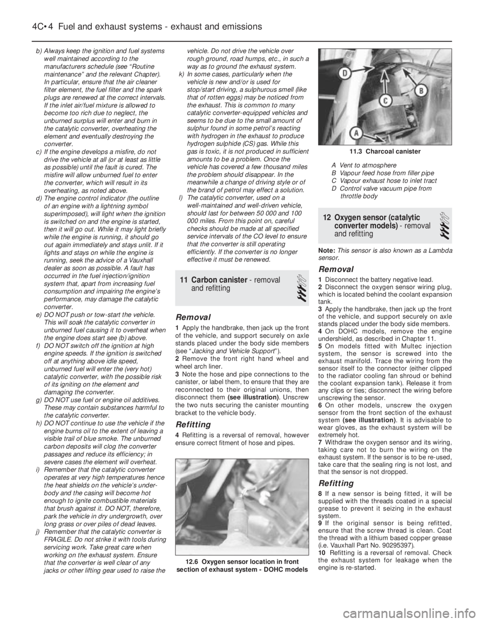
disconnect them (see illustration). Unscrew
the two nuts securing the canister mounting
bracket to the vehicle body.
Refitting
4Refitting is a reversal of removal, however
ensure correct fitment of hose and pipes.
12Oxygen sensor (catalytic
converter models) - removal
and refitting
3
Note: This sensor is also known as a Lambda
sensor.
Removal
1Disconnect the battery negative lead.
2Disconnect the oxygen sensor wiring plug,
which is located behind the coolant expansion
tank.
3Apply the handbrake, then jack up the front
of the vehicle, and support securely on axle
stands placed under the body side members.
4On DOHC models, remove the engine
undershield, as described in Chapter 11.
5On models fitted with Multec injection
system, the sensor is screwed into the
exhaust manifold. Trace the wiring from the
sensor itself to the connector (either clipped
to the radiator cooling fan shroud or behind
the coolant expansion tank). Release it from
any clips or ties; disconnect the wiring before
unscrewing the sensor.
6On other models, unscrew the oxygen
sensor from the front section of the exhaust
system (see illustration). It is advisable to
wear gloves, as the exhaust system will be
extremely hot.
7Withdraw the oxygen sensor and its wiring,
taking care not to burn the wiring on the
exhaust system. If the sensor is to be re-used,
take care that the sealing ring is not lost, and
that the sensor is not dropped.
Refitting
8If a new sensor is being fitted, it will be
supplied with the threads coated in a special
grease to prevent it seizing in the exhaust
system.
9If the original sensor is being refitted,
ensure that the screw thread is clean. Coat
the thread with a lithium based copper grease
(i.e. Vauxhall Part No. 90295397).
10Refitting is a reversal of removal. Check
the exhaust system for leakage when the
engine is re-started.
4C•4Fuel and exhaust systems - exhaust and emissions
12.6 Oxygen sensor location in front
section of exhaust system - DOHC models
11.3 Charcoal canister
A Vent to atmosphere
B Vapour feed hose from filler pipe
C Vapour exhaust hose to inlet tract
D Control valve vacuum pipe from
throttle body
Page 163 of 525
4Where applicable, the only test of the
catalytic converter’s efficiency is to check the
level of CO in the exhaust gas. This is
measured at the tailpipe with the engine
running (with no load) at 3000 rpm. If the CO
level exceeds the specified value, the Vauxhall
test equipment must be used to check the
entire fuel injection/ignition system. If the
engine is mechanically sound, once the
system has been eliminated, the fault must lie
in the converter, which must be renewed.
Motronic systems
Checking
5In order to check the idle mixture adjustment,
the following conditions must be met:
a)The engine must be at normal operating
temperature
b)All electrical consumers (cooling fan,
heater blower, headlamps etc.) must be
switched off
c)The spark plug gaps must be correctly
adjusted see Chapter 1
d)The throttle cable free play must be
correctly adjusted - see Section 19
e)The air inlet trunking must be free from
leaks, and the air filter must be clean
Adjustment
6Connect a tachometer and an exhaust gas
analyser to the vehicle in accordance with the
equipment manufacturer’s instructions.
7Start the engine and turn it at 2000 rpm for
approximately 30 seconds, then allow it to
idle. Check that the idle speed is within the
specified limits. No adjustment of idle speed
is possible, and if outside the specified limits,
the problem should be referred to a dealer.
8With the idle speed correct, check the CO
level in the exhaust gas. If it is outside the
specified limits, adjust by means of the idle
mixture adjustment screw in the airflow meter
or air mass meter, as applicable. In
production, the screw is covered by a
tamperproof plug; ensure that no local or
national laws are being broken before
removing the plug.9If the cooling fan cuts in during the
adjustment procedure, stop the adjustments,
and proceed when the cooling fan stops.
10When the idle mixture is correctly set,
stop the engine and disconnect the test
equipment.
Simtec systems
11Adjustment is not possible on these
models.
21Fuel pressure regulator -
removal and refitting
3
Note:Refer to Section 2 before proceeding
Removal
SOHC models (except Multec systems)
1Disconnect the battery negative lead.
2For improved access, remove the idle
speed adjuster as described in Section 22.
Disconnect the wiring harness housing from
the fuel injectors and move it to one side,
taking care not to strain the wiring. Pull up on
the wiring harness housing, and compress the
wiring plug retaining clips to release the
harness housing from the injectors.
3Position a wad of rag beneath the pressure
regulator, to absorb the fuel that will be
released as the regulator is removed.
4Loosen the clamp screws and disconnect
the fuel hoses from the regulator. Be prepared
for fuel spillage, and take adequate fire
precautions.
5Disconnect the vacuum pipe from the top
of the pressure regulator and withdraw the
regulator.
SOHC models (with Multec system)
6Depressurise the fuel system, as described
in Section 8.
7Remove the air box. Refer to Section 5, if
necessary.
8Disconnect the battery earth lead.9Noting the dowels locating the cover,
carefully unscrew the fuel pressure regulator
cover Torx-type screws (size TX 15). Ensure
that the spring does not fly out as the cover is
released. Remove the cover spring seat,
spring and diaphragm, noting how each is
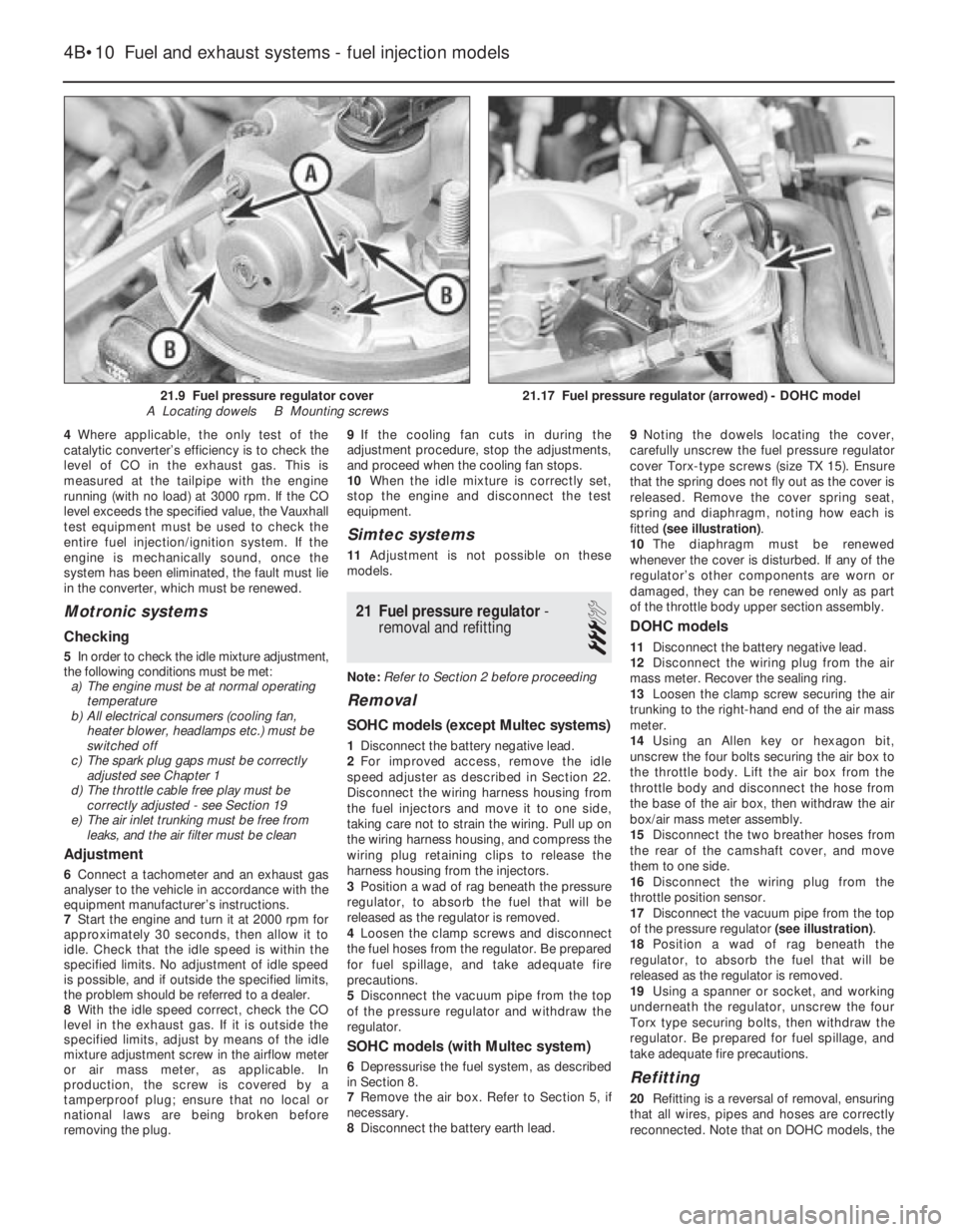
fitted (see illustration).
10The diaphragm must be renewed
whenever the cover is disturbed. If any of the
regulator’s other components are worn or
damaged, they can be renewed only as part
of the throttle body upper section assembly.
DOHC models
11Disconnect the battery negative lead.
12Disconnect the wiring plug from the air
mass meter. Recover the sealing ring.
13Loosen the clamp screw securing the air
trunking to the right-hand end of the air mass
meter.
14Using an Allen key or hexagon bit,
unscrew the four bolts securing the air box to
the throttle body. Lift the air box from the
throttle body and disconnect the hose from
the base of the air box, then withdraw the air
box/air mass meter assembly.
15Disconnect the two breather hoses from
the rear of the camshaft cover, and move
them to one side.
16Disconnect the wiring plug from the
throttle position sensor.
17Disconnect the vacuum pipe from the top
of the pressure regulator (see illustration).
18Position a wad of rag beneath the
regulator, to absorb the fuel that will be
released as the regulator is removed.
19Using a spanner or socket, and working
underneath the regulator, unscrew the four
Torx type securing bolts, then withdraw the
regulator. Be prepared for fuel spillage, and
take adequate fire precautions.
Refitting
20Refitting is a reversal of removal, ensuring
that all wires, pipes and hoses are correctly
reconnected. Note that on DOHC models, the
4B•10Fuel and exhaust systems - fuel injection models
21.17 Fuel pressure regulator (arrowed) - DOHC model21.9 Fuel pressure regulator cover
A Locating dowels B Mounting screws