1988 OPEL VECTRA cooling
[x] Cancel search: coolingPage 171 of 525
12Unscrew and remove the top alternator
mounting nut and bolt.
13Make a final check to ensure that all
relevant hoses, pipes and wires have been
disconnected.
14Unscrew the securing nuts, and withdraw
the manifold from the cylinder head. Recover
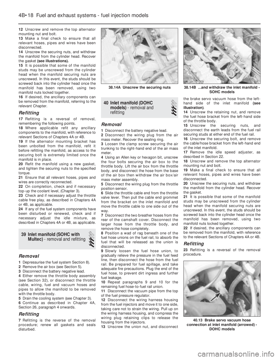
the gasket (see illustrations).
15It is possible that some of the manifold
studs may be unscrewed from the cylinder
head when the manifold securing nuts are
unscrewed. In this event, the studs should be
screwed back into the cylinder head once the
manifold has been removed, using two
manifold nuts locked together.
16If desired, the ancillary components can
be removed from the manifold, referring to the
relevant Chapter.
Refitting
17Refitting is a reversal of removal,
remembering the following points.
18Where applicable refit any ancillary
components to the manifold, with reference to
relevant Sections of Chapters 4A or 4B.
19If the alternator mounting bracket has
been unbolted from the manifold, refit it
before refitting the manifold, as access to the
securing bolt is extremely limited once the
manifold is in place.
20Refit the manifold using a new gasket,
and tighten the securing nuts to the specified
torque.
21Ensure that all relevant hoses, pipes and
wires are correctly reconnected.
22On completion, check and if necessary
top-up the coolant level, (Chapter 3).
23Check and if necessary adjust the throttle
cable free play, as described in Chapters 4A
or 4B, as applicable.
24If any of the fuel system components have
been disturbed or renewed, check and if
necessary adjust the idle mixture, as
described in Chapters 4A or 4B, as applicable.
39Inlet manifold (SOHCwith
Multec) - removal and refitting
3
Removal
1Depressurise the fuel system Section 8).
2Remove the air box (see Section 5).
3Disconnect the battery negative lead.
4Either remove the throttle body assembly
(see Section 32), or disconnect the throttle
cable, wiring, fuel and vacuum hoses and
pipes to allow the manifold to be removed
with the throttle body.
5Drain the cooling system (see Chapter 3).
6Continue as described in Chapter 4A,
Section 26, paragraph 4 onwards.
Refitting
7Refitting is the reverse of the removal
procedure; renew all gaskets and seals
disturbed.
40Inlet manifold (DOHC
models) - removal and
refitting
3
Removal
1Disconnect the battery negative lead.
2Disconnect the wiring plug from the air
mass meter. Recover the sealing ring.
3Loosen the clamp screw securing the air
trunking to the right-hand end of the air mass
meter.
4Using an Allen key or hexagon bit, unscrew
the four bolts securing the air box to the
throttle body. Lift the air box from the throttle
body, and disconnect the hose from the base
of the air box then withdraw the air box/air
mass meter assembly.
5Disconnect the wiring plug from the throttle
position sensor.
6Slide the throttle cable end from the throttle
valve lever. Then pull the cable end grommet
from the bracket on the inlet manifold and
move the throttle cable to one side out of the
way.
7Disconnect the two breather hoses from the
rear of the camshaft cover. Disconnect the
larger hose from the throttle body, and
remove the hose completely.
8Position a wad of rag beneath one of the
fuel hose unions on the fuel rail, to absorb the
fuel that will be released as the union is
disconnected.
9Slowly loosen the fuel hose union, to
gradually relieve the pressure in the fuel feed
line, then disconnect the hose from the fuel
rail. Be prepared for fuel spillage, and take
adequate fire precautions. Plug the end of the
fuel hose, to prevent dirt ingress and further
fuel leakage.
10Repeat paragraphs 9 and 10 for the
remaining fuel hose-to-fuel rail union.
11Disconnect the vacuum pipe from the top
of the fuel pressure regulator.
12Disconnect the wiring harness housing
from the fuel injectors and move it to one side,
taking care not to strain the wiring. Pull up on
the wiring harness housing, and compress the
wiring plug retaining clips to release the
housing from the injectors.
13Unscrew the union nut, and disconnectthe brake servo vacuum hose from the left-
hand side of the inlet manifold (see
illustration).
14Unscrew the retaining nut, and remove
the fuel hose bracket from the left-hand side
of the throttle body.
15Unscrew the securing nuts, and
disconnect the earth leads from the fuel rail
securing studs at either end of the fuel rail.
16Unscrew the securing bolt, and remove
the cable/hose bracket from the left-hand end
of the inlet manifold.
17Remove the idle speed adjuster, as
described in Section 22.
18Unscrew and remove the top alternator
mounting nut and bolt.
19Make a final check to ensure that all
relevant hoses, pipes and wires have been
disconnected.
20Unscrew the securing nuts, and withdraw
the manifold from the cylinder head. Recover
the gasket.
21It is possible that some of the manifold
studs may be unscrewed from the cylinder
head when the manifold securing nuts are
unscrewed. In this event, the studs should be
screwed back into the cylinder head once the
manifold has been removed, using two
manifold nuts locked together.
22If desired, the ancillary components can
be removed from the manifold, with reference
to the relevant Sections of Chapters 4A or 4B.
Refitting
23Refitting is a reversal of the removal
procedure.
4B•18Fuel and exhaust systems - fuel injection models
38.14A Unscrew the securing nuts
40.13 Brake servo vacuum hose
connection at inlet manifold (arrowed) -
DOHC models
38.14B ...and withdraw the inlet manifold -
SOHC models
Page 173 of 525
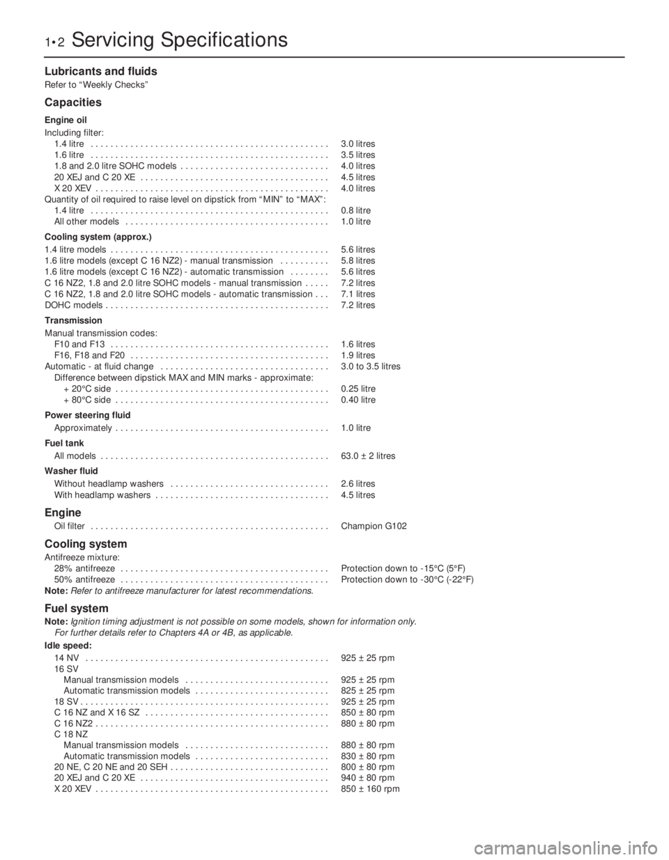
Lubricants and fluids
Refer to “Weekly Checks”
Capacities
Engine oil
Including filter:
1.4 litre . . . . . . . . . . . . . . . . . . . . . . . . . . . . . . . . . . . . . . . . . . . . . . . .3.0 litres
1.6 litre . . . . . . . . . . . . . . . . . . . . . . . . . . . . . . . . . . . . . . . . . . . . . . . .3.5 litres
1.8 and 2.0 litre SOHC models . . . . . . . . . . . . . . . . . . . . . . . . . . . . . .4.0 litres
20 XEJ and C 20 XE . . . . . . . . . . . . . . . . . . . . . . . . . . . . . . . . . . . . . .4.5 litres
X 20 XEV . . . . . . . . . . . . . . . . . . . . . . . . . . . . . . . . . . . . . . . . . . . . . . .4.0 litres
Quantity of oil required to raise level on dipstick from “MIN” to “MAX”:
1.4 litre . . . . . . . . . . . . . . . . . . . . . . . . . . . . . . . . . . . . . . . . . . . . . . . .0.8 litre
All other models . . . . . . . . . . . . . . . . . . . . . . . . . . . . . . . . . . . . . . . . .1.0 litre
Cooling system (approx.)
1.4 litre models . . . . . . . . . . . . . . . . . . . . . . . . . . . . . . . . . . . . . . . . . . . .5.6 litres
1.6 litre models (except C 16 NZ2) - manual transmission . . . . . . . . . .5.8 litres
1.6 litre models (except C 16 NZ2) - automatic transmission . . . . . . . .5.6 litres
C 16 NZ2, 1.8 and 2.0 litre SOHC models - manual transmission . . . . .7.2 litres
C 16 NZ2, 1.8 and 2.0 litre SOHC models - automatic transmission . . .7.1 litres
DOHC models . . . . . . . . . . . . . . . . . . . . . . . . . . . . . . . . . . . . . . . . . . . . .7.2 litres
Transmission
Manual transmission codes:
F10 and F13 . . . . . . . . . . . . . . . . . . . . . . . . . . . . . . . . . . . . . . . . . . . .1.6 litres
F16, F18 and F20 . . . . . . . . . . . . . . . . . . . . . . . . . . . . . . . . . . . . . . . .1.9 litres
Automatic - at fluid change . . . . . . . . . . . . . . . . . . . . . . . . . . . . . . . . . .3.0 to 3.5 litres
Difference between dipstick MAX and MIN marks -approximate:
+ 20°C side . . . . . . . . . . . . . . . . . . . . . . . . . . . . . . . . . . . . . . . . . . .0.25 litre
+ 80°C side . . . . . . . . . . . . . . . . . . . . . . . . . . . . . . . . . . . . . . . . . . .0.40 litre
Power steering fluid
Approximately . . . . . . . . . . . . . . . . . . . . . . . . . . . . . . . . . . . . . . . . . . .1.0 litre
Fuel tank
All models . . . . . . . . . . . . . . . . . . . . . . . . . . . . . . . . . . . . . . . . . . . . . .63.0 ±2 litres
Washer fluid
Without headlamp washers . . . . . . . . . . . . . . . . . . . . . . . . . . . . . . . .2.6 litres
With headlamp washers . . . . . . . . . . . . . . . . . . . . . . . . . . . . . . . . . . .4.5 litres
Engine
Oil filter . . . . . . . . . . . . . . . . . . . . . . . . . . . . . . . . . . . . . . . . . . . . . . . .Champion G102
Cooling system
Antifreeze mixture:
28% antifreeze . . . . . . . . . . . . . . . . . . . . . . . . . . . . . . . . . . . . . . . . . .Protection down to -15°C (5°F)
50% antifreeze . . . . . . . . . . . . . . . . . . . . . . . . . . . . . . . . . . . . . . . . . .Protection down to -30°C (-22°F)
Note:
Refer to antifreeze manufacturer for latest recommendations.
Fuel system
Note:Ignition timing adjustment is not possible on some models, shown for information only.
For further details refer to Chapters 4A or 4B, as applicable.
Idle speed:
14 NV . . . . . . . . . . . . . . . . . . . . . . . . . . . . . . . . . . . . . . . . . . . . . . . . .925 ±25 rpm
16 SV
Manual transmission models . . . . . . . . . . . . . . . . . . . . . . . . . . . . .925 ±25 rpm
Automatic transmission models . . . . . . . . . . . . . . . . . . . . . . . . . . .825 ±25 rpm
18 SV . . . . . . . . . . . . . . . . . . . . . . . . . . . . . . . . . . . . . . . . . . . . . . . . . .925 ±25 rpm
C 16 NZ and X 16 SZ . . . . . . . . . . . . . . . . . . . . . . . . . . . . . . . . . . . . .850 ±80 rpm
C 16 NZ2 . . . . . . . . . . . . . . . . . . . . . . . . . . . . . . . . . . . . . . . . . . . . . . .880 ±80 rpm
C 18 NZ
Manual transmission models . . . . . . . . . . . . . . . . . . . . . . . . . . . . .880 ±80 rpm
Automatic transmission models . . . . . . . . . . . . . . . . . . . . . . . . . . .830 ±80 rpm
20 NE, C 20 NE and 20 SEH . . . . . . . . . . . . . . . . . . . . . . . . . . . . . . . .800 ±80 rpm
20 XEJ and C 20 XE . . . . . . . . . . . . . . . . . . . . . . . . . . . . . . . . . . . . . .940 ±80 rpm
X 20 XEV . . . . . . . . . . . . . . . . . . . . . . . . . . . . . . . . . . . . . . . . . . . . . . .850 ±160 rpm
1•2Servicing Specifications
Page 176 of 525
Maintenance - component location 1•5
1
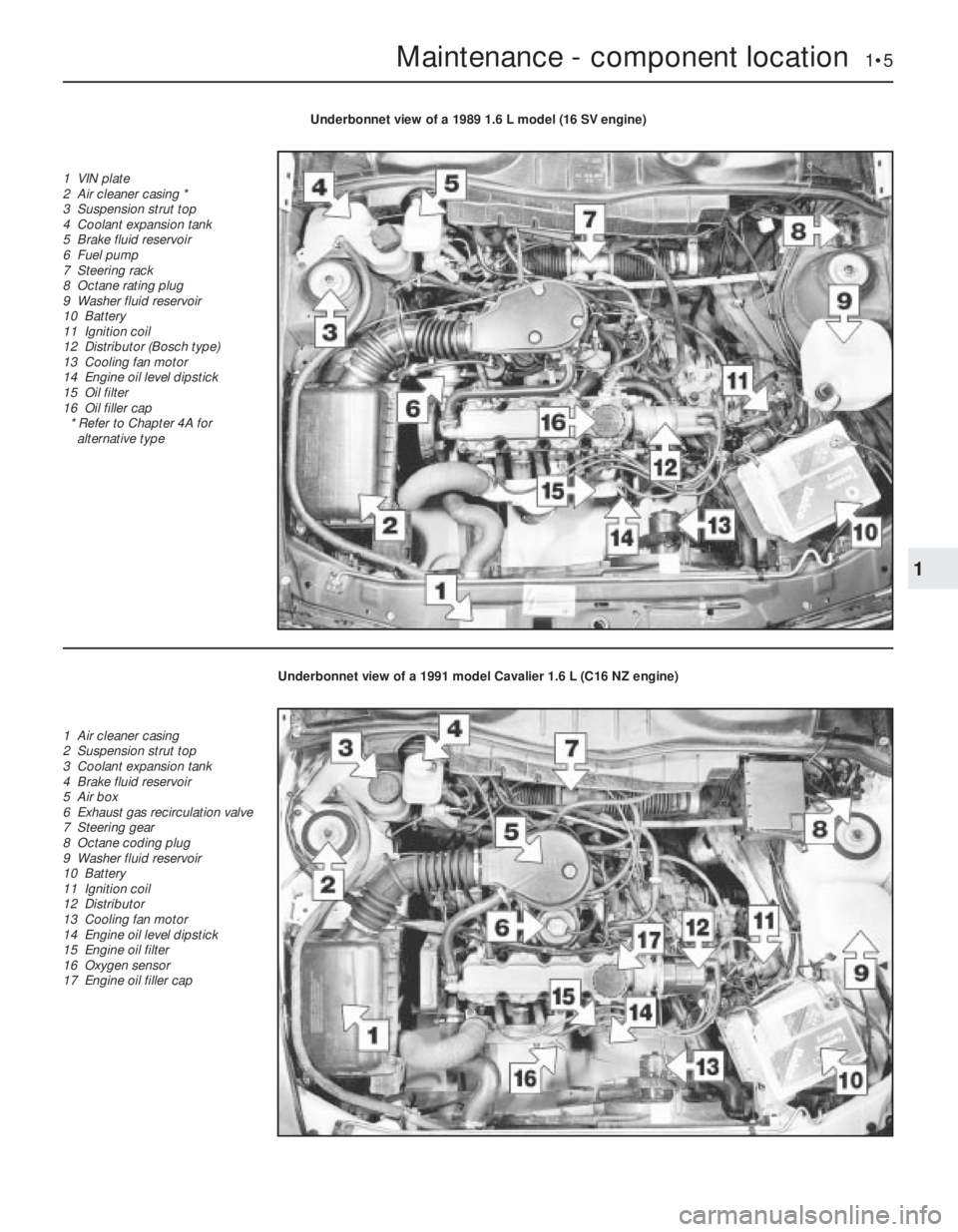
Underbonnet view of a 1989 1.6 L model (16 SV engine)
1 VIN plate
2 Air cleaner casing *
3 Suspension strut top
4 Coolant expansion tank
5 Brake fluid reservoir
6 Fuel pump
7 Steering rack
8 Octane rating plug
9 Washer fluid reservoir
10 Battery
11 Ignition coil
12 Distributor (Bosch type)
13 Cooling fan motor
14 Engine oil level dipstick
15 Oil filter
16 Oil filler cap
* Refer to Chapter 4A for
alternative type
Underbonnet view of a 1991 model Cavalier 1.6 L (C16 NZ engine)
1 Air cleaner casing
2 Suspension strut top
3 Coolant expansion tank
4 Brake fluid reservoir
5 Air box
6 Exhaust gas recirculation valve
7 Steering gear
8 Octane coding plug
9 Washer fluid reservoir
10 Battery
11 Ignition coil
12 Distributor
13 Cooling fan motor
14 Engine oil level dipstick
15 Engine oil filter
16 Oxygen sensor
17 Engine oil filler cap
Page 181 of 525
2Also check the security and condition of all
the engine related pipes and hoses. Ensure
that all cable-ties or securing clips are in
place, and in good condition. Clips that are
broken or missing can lead to chafing of the
hoses, pipes or wiring, which could cause
more serious problems in the future.
3Carefully check the radiator hoses and
heater hoses along their entire length. Renew
any hose that is cracked, swollen or
deteriorated. Cracks will show up better if the
hose is squeezed. Pay close attention to the
hose clips that secure the hoses to the
cooling system components. Hose clips can
pinch and puncture hoses, resulting in cooling
system leaks. It is always beneficial to renew
hose clips whenever possible.
4Inspect all the cooling system components
(hoses, joint faces, etc.) for leaks.
5Where any problems are found on system
components, renew the component or gasket
with reference to Chapter 3.
6Where applicable, inspect the automatic
transmission fluid cooler hoses for leaks or
deterioration.
7With the vehicle raised, inspect the petrol
tank and filler neck for punctures, cracks and
other damage. The connection between the
filler neck and tank is especially critical.
Sometimes a rubber filler neck or connecting
hose will leak due to loose retaining clamps or
deteriorated rubber.
8Carefully check all rubber hoses and metal
fuel lines leading away from the petrol tank.
Check for loose connections, deteriorated
hoses, crimped lines, and other damage. Pay
particular attention to the vent pipes and
hoses, which often loop up around the filler
neck and can become blocked or crimped.
Follow the lines to the front of the vehicle,
carefully inspecting them all the way. Renew
damaged sections as necessary.
9From within the engine compartment,
check the security of all fuel hose attachments
and pipe unions, and inspect the fuel hoses
and vacuum hoses for kinks, chafing and
deterioration.
10Where applicable, check the condition of
the power steering fluid hoses and pipes.5Steering and suspension
check
2
Front suspension and steering
check
1Raise the front of the car, and support on
axle stands (“Jacking and Vehicle Support”).
2Visually inspect the balljoint dust covers
and the steering rack-and-pinion gaiters for
splits, chafing or deterioration. Any wear of
these components will cause loss of lubricant,
together with dirt and water entry, resulting in
rapid wear of the balljoints or steering gear.
3On vehicles with power steering, check the
fluid hoses for chafing or deterioration, and
the pipe and hose unions for fluid leaks. Also
check for signs of fluid leakage under
pressure from the steering gear rubber
gaiters, which would indicate failed fluid seals
within the steering gear.
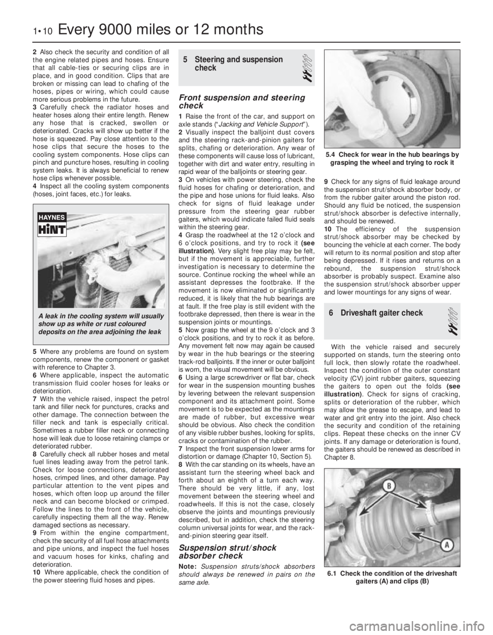
4Grasp the roadwheel at the 12 o’clock and
6 o’clock positions, and try to rock it (see
illustration). Very slight free play may be felt,
but if the movement is appreciable, further
investigation is necessary to determine the
source. Continue rocking the wheel while an
assistant depresses the footbrake. If the
movement is now eliminated or significantly
reduced, it is likely that the hub bearings are
at fault. If the free play is still evident with the
footbrake depressed, then there is wear in the
suspension joints or mountings.
5Now grasp the wheel at the 9 o’clock and 3
o’clock positions, and try to rock it as before.
Any movement felt now may again be caused
by wear in the hub bearings or the steering
track-rod balljoints. If the inner or outer balljoint
is worn, the visual movement will be obvious.
6Using a large screwdriver or flat bar, check
for wear in the suspension mounting bushes
by levering between the relevant suspension
component and its attachment point. Some
movement is to be expected as the mountings
are made of rubber, but excessive wear
should be obvious. Also check the condition
of any visible rubber bushes, looking for splits,
cracks or contamination of the rubber.
7Inspect the front suspension lower arms for
distortion or damage (Chapter 10, Section 5).
8With the car standing on its wheels, have an
assistant turn the steering wheel back and
forth about an eighth of a turn each way.
There should be very little, if any, lost
movement between the steering wheel and
roadwheels. If this is not the case, closely
observe the joints and mountings previously
described, but in addition, check the steering
column universal joints for wear, and the rack-
and-pinion steering gear itself.
Suspension strut/shock
absorber check
Note:Suspension struts/shock absorbers
should always be renewed in pairs on the
same axle.9Check for any signs of fluid leakage around
the suspension strut/shock absorber body, or
from the rubber gaiter around the piston rod.
Should any fluid be noticed, the suspension
strut/shock absorber is defective internally,
and should be renewed.
10The efficiency of the suspension
strut/shock absorber may be checked by
bouncing the vehicle at each corner. The body
will return to its normal position and stop after
being depressed. If it rises and returns on a
rebound, the suspension strut/shock
absorber is probably suspect. Examine also
the suspension strut/shock absorber upper
and lower mountings for any signs of wear.
6Driveshaft gaiter check
2
With the vehicle raised and securely
supported on stands, turn the steering onto
full lock, then slowly rotate the roadwheel.
Inspect the condition of the outer constant
velocity (CV) joint rubber gaiters, squeezing
the gaiters to open out the folds (see
illustration). Check for signs of cracking,
splits or deterioration of the rubber, which
may allow the grease to escape, and lead to
water and grit entry into the joint. Also check
the security and condition of the retaining
clips. Repeat these checks on the inner CV
joints. If any damage or deterioration is found,
the gaiters should be renewed as described in
Chapter 8.
1•10Every 9000 miles or 12 months
6.1 Check the condition of the driveshaft
gaiters (A) and clips (B)
5.4 Check for wear in the hub bearings by
grasping the wheel and trying to rock it
A leak in the cooling system will usually
show up as white or rust coloured
deposits on the area adjoining the leak
Page 194 of 525
pitting. If evident, the cylinder head and all
bearing caps must be renewed as a matched
set, as there is no provision for refacing if the
bearing caps cannot be renewed individually.
8The camshaft(s) should show no marks or
scoring on the journal or cam lobe surfaces. if
evident, renew the camshaft(s).
9It is advisable to renew the camshaft front
oil seal(s) as a matter of course. Prise the old
seal(s) from the front of the camshaft(s) and
discard them.
Refitting
10Begin refitting by liberally coating the
contact faces of the hydraulic valve lifters and
the camshaft(s) with molybdenum disulphide
paste.
11Coat the mating faces of the front and
rear bearing caps with sealing compound and
refit the bearing caps in their original positions
as noted during removal.
12Tighten the camshaft bearing cap nuts to
the specified torque in half-turn stages, as
when loosening the nuts. Note that when
refitting the exhaust camshaft, the two smaller
rear bearing cap securing nuts should be
tightened after all the main camshaft bearing
cap nuts have been tightened. Note also that
the two smaller nuts should be tightened to a
lower torque wrench setting than the main
nuts.
13Turn the camshaft until the locating peg
for the camshaft sprocket is uppermost, then
lubricate the lips of a rear camshaft front oil
seal with a little grease, and fit the oil seal,
using a tube or socket of similar diameter with
a washer and the camshaft sprocket bolt.
Screw the camshaft sprocket bolt into the end
of the camshaft to draw the oil seal into
position on its shoulder.
14Repeat the procedure for the remaining
camshaft.
15Refit the distributor with reference to
Chapter 5. Fit a new timing belt and the
camshaft sprockets, then adjust the timing
belt as described in Section 4 or 5, as
applicable.
8Cylinder head -removal and
refitting (engine in vehicle)
4
Note: The engine must be cold when the
cylinder head is removed. Do not remove the
cylinder head from a hot engine. New cylinder
head bolts, a new cylinder head gasket and a
new timing belt must be used on refitting.
The torque settings (as shown in Chapter 2A)
are only applicable to latest specification head
bolts, available from Vauxhall. Earlier type or
alternative make, head bolts may require
different torques. Consult your supplier
Removal
1Disconnect the battery negative lead.
2Drain the cooling system, as described in
Chapter 3.3Remove the front section of the exhaust
system, as described in Chapter 4C.
4The cylinder head can be removed
complete with the inlet manifold, or the inlet
manifold can be detached from the cylinder
head before removal, with reference to
Chapter 4B. If no work is to be carried out on
the inlet manifold, it can be unbolted from the
cylinder head and supported to one side out
of the way, thus avoiding the need to
disconnect the relevant hoses, pipes and
wiring.
5If the cylinder head is to be removed
complete with the inlet manifold, disconnect
all relevant hoses, pipes and wiring from the
inlet manifold and associated components,
referring to Chapter 4B, and unbolt the
manifold support bracket from the manifold.
Loosen the alternator mountings with
reference to Chapter 5, then unbolt the upper
alternator mounting from the inlet manifold.
6If the inlet manifold is to be left in the engine
compartment, continue as follows, otherwise
go on to paragraph 17.
7Disconnect the wiring plug from the airflow
meter, and the breather hose from the air box
on the throttle body. Disconnect the air
cleaner trunking and remove the airflow
meter/air box assembly from the throttle
body. Refer to Chapter 4B if necessary.
8Disconnect the end of the throttle cable
from the throttle valve lever, then unbolt the
throttle cable support bracket and remove it
from the inlet manifold.
9Unscrew the two earth lead securing nuts
from the fuel rail (one at each end of the rail)
and disconnect the three earth leads.
10Disconnect the wiring plug from the
throttle position switch.
11Pull up on the wiring harness housing, and
disconnect the wiring plugs from the fuel
injectors by compressing the retaining clips.
Move the wiring harness housing to one side.
12Disconnect the two breather hoses from
the rear of the camshaft cover.
13Loosen the alternator mountings, with
reference to Chapter 5, then unbolt the upper
alternator mounting from the inlet manifold.
14Unbolt the manifold support bracket from
the manifold.15Make a final check to ensure that all
necessary hoses, pipes and wires have been
disconnected, then unscrew the securing nuts
and lift the inlet manifold from the cylinder
head. Ensure that the manifold is properly
supported, taking care not to strain any of the
hoses, pipes and wires, etc., which are still
connected.
16Recover the manifold gasket from the
cylinder head.
17Remove the timing belt, camshaft
sprockets, and timing belt tensioner and idler
pulleys, as described in Section 4.
18Unscrew the upper and middle studs for
the timing belt outer cover screws. Note that
the upper stud simply unscrews from the
cylinder head, but the middle stud is secured
by a bolt.
19Unscrew the two upper rear timing belt
cover securing bolts from the cylinder head.
20Remove the distributor cap and HT leads
with reference to Chapter 5.
21Disconnect the distributor wiring plug.
22Disconnect the coolant hose from the
left-hand end of the cylinder head.
23Unscrew the bolt securing the crankcase
breather tube bracket to the end of the
cylinder head.
24Disconnect the radiator top hose from the
thermostat housing, and disconnect the
wiring plugs from the temperature gauge
sender and the coolant temperature sensor
(both situated in the thermostat housing).
25Make a final check to ensure that all
relevant hoses, pipes and wires have been
disconnected.
26On X20 XEV models, remove the
camshaft, as described in Section 7.
27Using a Torx socket, and working in the
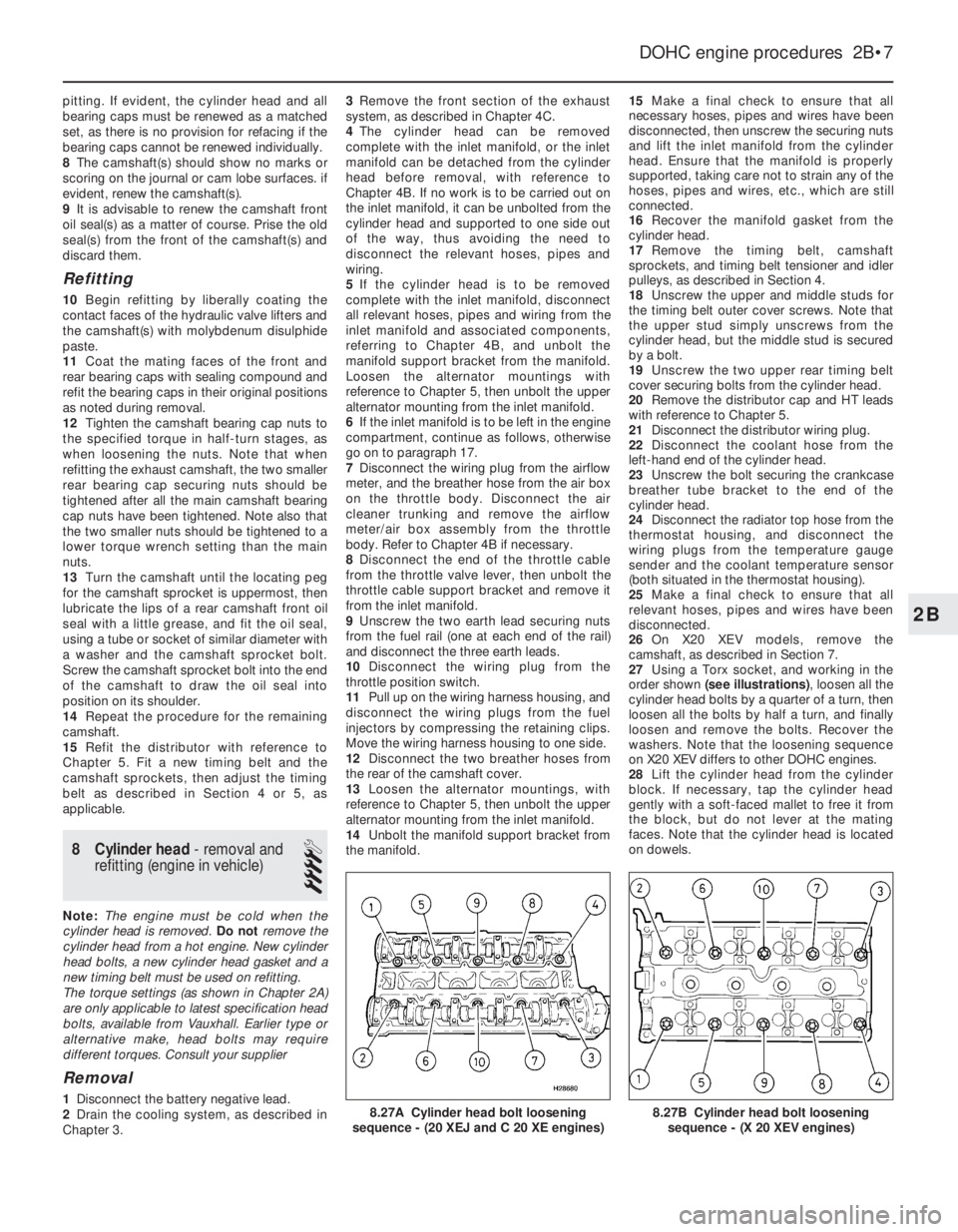
order shown (see illustrations), loosen all the
cylinder head bolts by a quarter of a turn, then
loosen all the bolts by half a turn, and finally
loosen and remove the bolts. Recover the
washers. Note that the loosening sequence
on X20 XEV differs to other DOHC engines.
28Lift the cylinder head from the cylinder
block. If necessary, tap the cylinder head
gently with a soft-faced mallet to free it from
the block, but do not lever at the mating
faces. Note that the cylinder head is located
on dowels.
DOHC engine procedures 2B•7
8.27B Cylinder head bolt loosening
sequence - (X 20 XEV engines)8.27A Cylinder head bolt loosening
sequence - (20 XEJ and C 20 XE engines)
2B
Page 195 of 525
29Recover the cylinder head gasket and
discard it.
30Clean the cylinder head and block mating
faces by careful scraping. Take care not to
damage the cylinder head, which is made of
light alloy and is easily scored. Cover the
coolant passages and other openings with
masking tape or rag, to prevent dirt and
carbon falling in. Mop out all the oil from the
bolt holes; if oil is left in the holes, hydraulic
pressure could crack the block when the bolts
are refitted.
31If desired, the cylinder head can be
dismantled and inspected as described in
Section 10.
Refitting
32Begin refitting by locating a new gasket
on the block so that the word “OBEN” or
“TOP” is uppermost at the timing belt end of
the engine.
33With the mating faces scrupulously clean,
locate the cylinder head on the block so that
the positioning dowels engage in their holes.
34Temporarily refit the crankshaft pulley and
the camshaft sprockets, and ensure that the
timing marks are still positioned as they were
before the timing belt was removed (see
Section 4).35Fit the new cylinder head bolts, ensuring
that the washers are in place under their
heads, and screw the bolts in by hand as far
as possible.
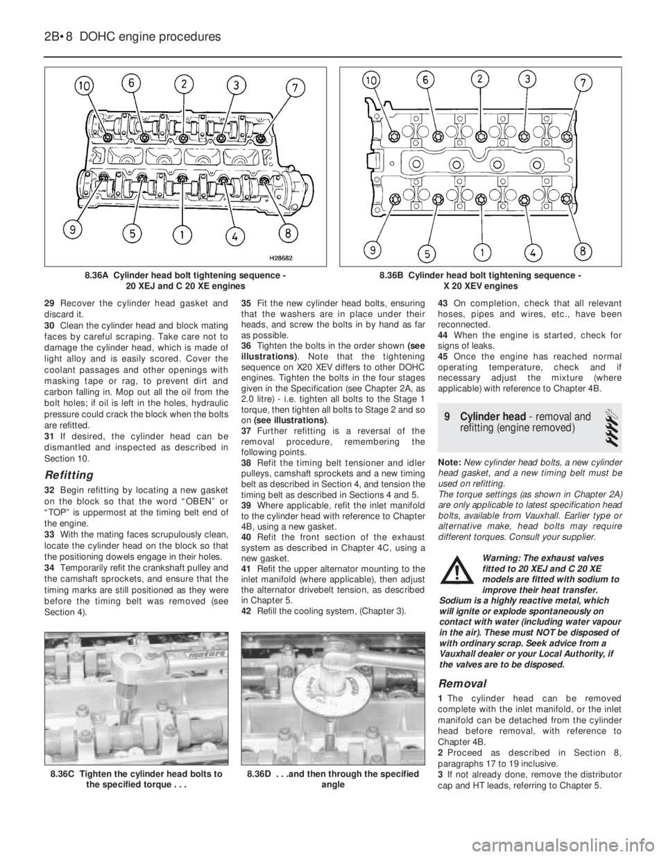
36Tighten the bolts in the order shown (see
illustrations). Note that the tightening
sequence on X20 XEV differs to other DOHC
engines. Tighten the bolts in the four stages
given in the Specification (see Chapter 2A, as
2.0 litre) - i.e. tighten all bolts to the Stage 1
torque, then tighten all bolts to Stage 2 and so
on (see illustrations).
37Further refitting is a reversal of the
removal procedure, remembering the
following points.
38Refit the timing belt tensioner and idler
pulleys, camshaft sprockets and a new timing
belt as described in Section 4, and tension the
timing belt as described in Sections 4 and 5.
39Where applicable, refit the inlet manifold
to the cylinder head with reference to Chapter
4B, using a new gasket.
40Refit the front section of the exhaust
system as described in Chapter 4C, using a
new gasket.
41Refit the upper alternator mounting to the
inlet manifold (where applicable), then adjust
the alternator drivebelt tension, as described
in Chapter 5.
42Refill the cooling system, (Chapter 3).43On completion, check that all relevant
hoses, pipes and wires, etc., have been
reconnected.
44When the engine is started, check for
signs of leaks.
45Once the engine has reached normal
operating temperature, check and if
necessary adjust the mixture (where
applicable) with reference to Chapter 4B.
9Cylinder head -removal and
refitting (engine removed)
4
Note: New cylinder head bolts, a new cylinder
head gasket, and a new timing belt must be
used on refitting.
The torque settings (as shown in Chapter 2A)
are only applicable to latest specification head
bolts, available from Vauxhall. Earlier type or
alternative make, head bolts may require
different torques. Consult your supplier.
Removal
1The cylinder head can be removed
complete with the inlet manifold, or the inlet
manifold can be detached from the cylinder
head before removal, with reference to
Chapter 4B.
2Proceed as described in Section 8,
paragraphs 17 to 19 inclusive.
3If not already done, remove the distributor
cap and HT leads, referring to Chapter 5.
2B•8DOHC engine procedures
8.36A Cylinder head bolt tightening sequence -
20 XEJ and C 20 XE engines
8.36C Tighten the cylinder head bolts to
the specified torque . . .8.36D . . .and then through the specified
angle
8.36B Cylinder head bolt tightening sequence -
X 20 XEV engines
Warning: The exhaust valves
fitted to 20 XEJ and C 20 XE
models are fitted with sodium to
improve their heat transfer.
Sodium is a highly reactive metal, which
will ignite or explode spontaneously on
contact with water (including water vapour
in the air). These must NOT be disposed of
with ordinary scrap. Seek advice from a
Vauxhall dealer or your Local Authority, if
the valves are to be disposed.
Page 205 of 525
the cylinder head above the camshaft(s)
through a hose. From here the gases are
drawn into the inlet manifold/throttle body (as
applicable) and/or the air box on the
carburettor (where applicable), where they are
re-burnt with fresh air/fuel mixture, hence
reducing harmful exhaust emissions.
Maintenance
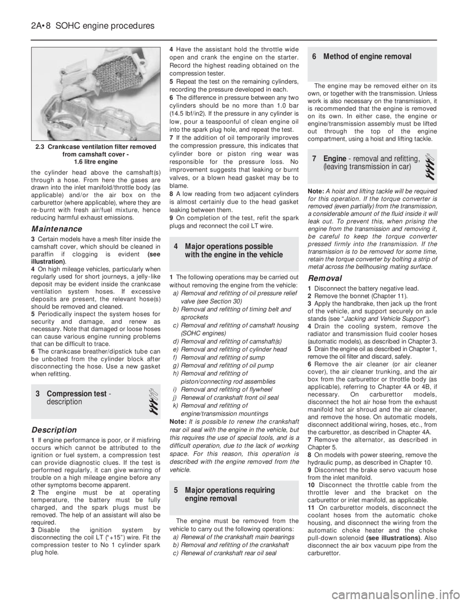
3Certain models have a mesh filter inside the
camshaft cover, which should be cleaned in
paraffin if clogging is evident (see
illustration).
4On high mileage vehicles, particularly when
regularly used for short journeys, a jelly-like
deposit may be evident inside the crankcase
ventilation system hoses. If excessive
deposits are present, the relevant hose(s)
should be removed and cleaned.
5Periodically inspect the system hoses for
security and damage, and renew as
necessary. Note that damaged or loose hoses
can cause various engine running problems
that can be difficult to trace.
6The crankcase breather/dipstick tube can
be unbolted from the cylinder block after
disconnecting the hose. Use a new gasket
when refitting.
3Compression test -
description
3
Description
1If engine performance is poor, or if misfiring
occurs which cannot be attributed to the
ignition or fuel system, a compression test
can provide diagnostic clues. If the test is
performed regularly, it can give warning of
trouble on a high mileage engine before any
other symptoms become apparent.
2The engine must be at operating
temperature, the battery must be fully
charged, and the spark plugs must be
removed. The help of an assistant will also be
required.
3Disable the ignition system by
disconnecting the coil LT (“+15”) wire. Fit the
compression tester to No 1 cylinder spark
plug hole.4Have the assistant hold the throttle wide
open and crank the engine on the starter.
Record the highest reading obtained on the
compression tester.
5Repeat the test on the remaining cylinders,
recording the pressure developed in each.
6The difference in pressure between any two
cylinders should be no more than 1.0 bar
(14.5 lbf/in2). If the pressure in any cylinder is
low, pour a teaspoonful of clean engine oil
into the spark plug hole, and repeat the test.
7If the addition of oil temporarily improves
the compression pressure, this indicates that
cylinder bore or piston ring wear was
responsible for the pressure loss. No
improvement suggests that leaking or burnt
valves, or a blown head gasket may be to
blame.
8A low reading from two adjacent cylinders
is almost certainly due to the head gasket
leaking between them.
9On completion of the test, refit the spark
plugs and reconnect the coil LT wire.
4Major operations possible
with the engine in the vehicle
1The following operations may be carried out
without removing the engine from the vehicle:
a)Removal and refitting of oil pressure relief
valve (see Section 30)
b)Removal and refitting of timing belt and
sprockets
c)Removal and refitting of camshaft housing
(SOHC engines)
d)Removal and refitting of camshaft(s)
e)Removal and refitting of cylinder head
f)Removal and refitting of sump
g)Removal and refitting of oil pump
h)Removal and refitting of
piston/connecting rod assemblies
i)Removal and refitting of flywheel
j)Renewal of crankshaft front oil seal
k)Removal and refitting of
engine/transmission mountings
Note: It is possible to renew the crankshaft
rear oil seal with the engine in the vehicle, but
this requires the use of special tools, and is a
difficult operation, due to the lack of working
space. For this reason, this operation is
described with the engine removed from the
vehicle.
5Major operations requiring
engine removal
The engine must be removed from the
vehicle to carry out the following operations:
a)Renewal of the crankshaft main bearings
b)Removal and refitting of the crankshaft
c)Renewal of crankshaft rear oil seal
6Method of engine removal
The engine may be removed either on its
own, or together with the transmission. Unless
work is also necessary on the transmission, it
is recommended that the engine is removed
on its own. In either case, the engine or
engine/transmission assembly must be lifted
out through the top of the engine
compartment, using a hoist and lifting tackle.
7Engine - removal and refitting,
(leaving transmission in car)
4
Note: A hoist and lifting tackle will be required
for this operation.If the torque converter is
removed (even partially) from the transmission,
a considerable amount of the fluid inside it will
leak out. To prevent this, when prising the
engine from the transmission and removing it,
be careful to keep the torque converter
pressed firmly into the transmission. If the
transmission is to be removed for some time,
retain the torque converter by bolting a strip of
metal across the bellhousing mating surface.
Removal
1Disconnect the battery negative lead.
2Remove the bonnet (Chapter 11).
3Apply the handbrake, then jack up the front
of the vehicle, and support securely on axle
stands (see “Jacking and Vehicle Support”).
4Drain the cooling system, remove the
radiator and transmission fluid cooler hoses
(automatic models), as described in Chapter 3.
5Drain the engine oil as described in Chapter 1,
remove the oil filter and discard, safely.
6Remove the air cleaner (or air cleaner
cover), the air cleaner trunking, and the air
box from the carburettor or throttle body (as
applicable), referring to Chapter 4A or 4B, if
necessary. On carburettor models,
disconnect the hot air hose from the exhaust
manifold hot air shroud and the air cleaner,
and remove the hose. On automatic models,
disconnect additional wiring, hoses, etc., from
the carburettor, as described in Chapter 4A.
7Remove the alternator, as described in
Chapter 5.
8On models with power steering, remove the
hydraulic pump, as described in Chapter 10.
9Disconnect the brake servo vacuum hose
from the inlet manifold.
10Disconnect the throttle cable from the
throttle lever and the bracket on the
carburettor or inlet manifold, as applicable.
11On carburettor models, disconnect the
coolant hoses from the automatic choke
housing, and disconnect the wiring from the
automatic choke heater and the choke
pull-down solenoid (see illustrations). Also
disconnect the air box vacuum pipe from the
carburettor.
2A•8SOHC engine procedures
2.3 Crankcase ventilation filter removed
from camshaft cover -
1.6 litre engine
Page 207 of 525
30With the engine removed, the
transmission can be supported by placing a
length of wood between the bellhousing and
the front suspension subframe. Once the
wooden support is in place, remove the trolley
jack from under the transmission.
Refitting
Note: New left and right-hand
engine/transmission mounting-to-body bolts
must be used on refitting.
31Use an M10 x 1.25 bottoming tap to clean
the threads in the torque converters threaded
bosses and ensure that new bolts are
available for reassembly, where applicable.
32Support the transmission with a trolley
jack and remove the length of wood from
between the bellhousing and the subframe.
33Support the engine with the hoist and
lifting tackle, and gently lower it into position
in the engine compartment.
34Mate the engine and transmission
together, ensuring that the transmission
locates on the dowels in the cylinder block,
then refit the three upper
engine-to-transmission bolts.
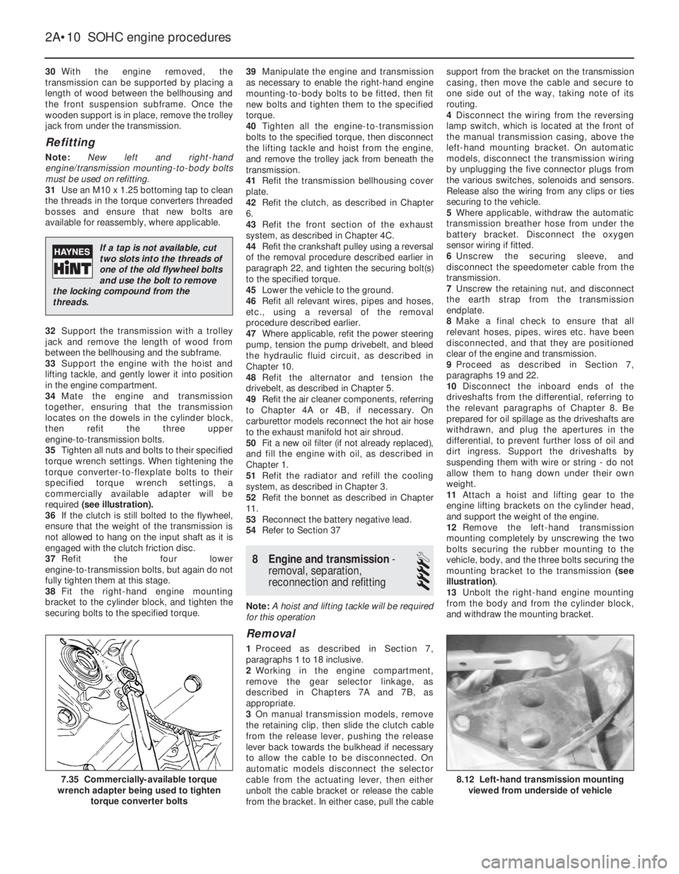
35Tighten all nuts and bolts to their specified
torque wrench settings. When tightening the
torque converter-to-flexplate bolts to their
specified torque wrench settings, a
commercially available adapter will be
required (see illustration).
36If the clutch is still bolted to the flywheel,
ensure that the weight of the transmission is
not allowed to hang on the input shaft as it is
engaged with the clutch friction disc.
37Refit the four lower
engine-to-transmission bolts, but again do not
fully tighten them at this stage.
38Fit the right-hand engine mounting
bracket to the cylinder block, and tighten the
securing bolts to the specified torque.39Manipulate the engine and transmission
as necessary to enable the right-hand engine
mounting-to-body bolts to be fitted, then fit
new bolts and tighten them to the specified
torque.
40Tighten all the engine-to-transmission
bolts to the specified torque, then disconnect
the lifting tackle and hoist from the engine,
and remove the trolley jack from beneath the
transmission.
41Refit the transmission bellhousing cover
plate.
42Refit the clutch, as described in Chapter
6.
43Refit the front section of the exhaust
system, as described in Chapter 4C.
44Refit the crankshaft pulley using a reversal
of the removal procedure described earlier in
paragraph 22, and tighten the securing bolt(s)
to the specified torque.
45Lower the vehicle to the ground.
46Refit all relevant wires, pipes and hoses,
etc., using a reversal of the removal
procedure described earlier.
47Where applicable, refit the power steering
pump, tension the pump drivebelt, and bleed
the hydraulic fluid circuit, as described in
Chapter 10.
48Refit the alternator and tension the
drivebelt, as described in Chapter 5.
49Refit the air cleaner components, referring
to Chapter 4A or 4B, if necessary. On
carburettor models reconnect the hot air hose
to the exhaust manifold hot air shroud.
50Fit a new oil filter (if not already replaced),
and fill the engine with oil, as described in
Chapter 1.
51Refit the radiator and refill the cooling
system, as described in Chapter 3.
52Refit the bonnet as described in Chapter
11.
53Reconnect the battery negative lead.
54Refer to Section 37
8Engine and transmission -
removal, separation,
reconnection and refitting
4
Note: A hoist and lifting tackle will be required
for this operation
Removal
1Proceed as described in Section 7,
paragraphs 1 to 18 inclusive.
2Working in the engine compartment,
remove the gear selector linkage, as
described in Chapters 7A and 7B, as
appropriate.
3On manual transmission models, remove
the retaining clip, then slide the clutch cable
from the release lever, pushing the release
lever back towards the bulkhead if necessary
to allow the cable to be disconnected. On
automatic models disconnect the selector
cable from the actuating lever, then either
unbolt the cable bracket or release the cable
from the bracket. In either case, pull the cablesupport from the bracket on the transmission
casing, then move the cable and secure to
one side out of the way, taking note of its
routing.
4Disconnect the wiring from the reversing
lamp switch, which is located at the front of
the manual transmission casing, above the
left-hand mounting bracket. On automatic
models, disconnect the transmission wiring
by unplugging the five connector plugs from
the various switches, solenoids and sensors.
Release also the wiring from any clips or ties
securing to the vehicle.
5Where applicable, withdraw the automatic
transmission breather hose from under the
battery bracket. Disconnect the oxygen
sensor wiring if fitted.
6Unscrew the securing sleeve, and
disconnect the speedometer cable from the
transmission.
7Unscrew the retaining nut, and disconnect
the earth strap from the transmission
endplate.
8Make a final check to ensure that all
relevant hoses, pipes, wires etc. have been
disconnected, and that they are positioned
clear of the engine and transmission.
9Proceed as described in Section 7,
paragraphs 19 and 22.
10Disconnect the inboard ends of the
driveshafts from the differential, referring to
the relevant paragraphs of Chapter 8. Be
prepared for oil spillage as the driveshafts are
withdrawn, and plug the apertures in the
differential, to prevent further loss of oil and
dirt ingress. Support the driveshafts by
suspending them with wire or string - do not
allow them to hang down under their own
weight.
11Attach a hoist and lifting gear to the
engine lifting brackets on the cylinder head,
and support the weight of the engine.
12Remove the left-hand transmission
mounting completely by unscrewing the two
bolts securing the rubber mounting to the
vehicle, body, and the three bolts securing the
mounting bracket to the transmission (see
illustration).
13Unbolt the right-hand engine mounting
from the body and from the cylinder block,
and withdraw the mounting bracket.
2A•10SOHC engine procedures
8.12 Left-hand transmission mounting
viewed from underside of vehicle7.35 Commercially-available torque
wrench adapter being used to tighten
torque converter bolts
If a tap is not available, cut
two slots into the threads of
one of the old flywheel bolts
and use the bolt to remove
the locking compound from the
threads.