1988 OPEL CALIBRA key
[x] Cancel search: keyPage 184 of 525

tighten the mounting nuts and bolts. On no
account lever at the free end of the alternator,
as serious internal damage could be caused.
3For details of replacement, see Chapter 5.
23Headlamp alignment
2
Refer to Chapter 12 for details.
24Door lock key battery -
replacement
1
1Carefully prise open the outer cover from
the key. Take care not to lose any of the
internal components, as they are loose.
2Remove the battery and discard it safely.
3Place the new battery, “+” side up (see
illustration). Check the operation of the key. If
the bulb does not light obtain a replacement.
4Replace the outer cover.
25Road test
1
Instruments and electrical
equipment
1Check the operation of all instruments and
electrical equipment.
2Make sure that all instruments read
correctly, and switch on all electrical
equipment in turn to check that it functions
properly.
Steering and suspension
3Check for any abnormalities in the steering,
suspension, handling or road “feel”.
4Drive the vehicle, and check that there are
no unusual vibrations or noises.5Check that the steering feels positive, with
no excessive “sloppiness”, or roughness, and
check for any suspension noises when
cornering, or when driving over bumps.
Drivetrain
6Check the performance of the engine,
clutch, transmission and driveshafts.
7Turn the radio/cassette off and listen for
any unusual noises from the engine, clutch
and transmission.
8Make sure that the engine runs smoothly
when idling, and that there is no hesitation
when accelerating.
9Check that the clutch action is smooth and
progressive, that the drive is taken up
smoothly, and that the pedal travel is not
excessive. Also listen for any noises when the
clutch pedal is depressed.
10Check that all gears can be engaged
smoothly, without noise, and that the gear
lever action is not abnormally vague or
“notchy”.
11Listen for a metallic clicking sound from
the front of the vehicle, as the vehicle is driven
slowly in a circle with the steering on full lock.
Carry out this check in both directions. If a
clicking noise is heard, this indicates wear in a
driveshaft joint, in which case, the complete
driveshaft must be renewed (see Chapter 8).
26Coolant renewal
2
Refer to Chapter 3 for details.
27Air cleaner element - renewal
2
Early round type
1Release the spring clips from the perimeter
of the air cleaner cover.
2Unscrew and remove the small cross-head
screw securing the cover extension to the
main body near the inlet duct.3Unscrew and remove the three central
cross-head cap nuts securing the air cleaner
to the carburettor, taking care not to drop the
washers and seals (see illustration).
4Separate the cover from the main body,
then lift out the element (see illustration).
5Wipe clean the inside surfaces of the cover
and main body.
6Locate the new element in the air cleaner
body, and refit the cover using a reversal of
the removal procedure.
Square type with air box
7If desired, to improve access, unclip the
coolant expansion tank hose from the air
cleaner cover.
8Release the two clips from the left-hand
side of the cover, and unscrew the two
screws from the right-hand side, then lift the
cover sufficiently to remove the element.
9Wipe clean the inside surfaces of the cover
and main body.
10Refitting is a reversal of removal, noting
that the element fits with the rubber locating
flange uppermost.
Every 18 000 miles or 24 months 1•13
24.3 Replacing the battery in the door lock
key
1 Battery (note, positive ‘+’ side up)
2 Bulb
27.4 Removing the air cleaner element -
note clip for crankcase ventilation hose
(arrowed)
27.3 Air cleaner-to-carburettor mounting
cap nuts
1
Full service, every 18 000 miles (30 000 km) or 24 months
Warning: Wait until the engine is
cold before starting the
procedure. Do not allow
antifreeze to come in contact
with your skin or with painted surfaces of
the vehicle. Rinse off spills with plenty of
water. Never leave antifreeze lying around
in an open container. Always clean spilt
fluids, as it can be harmful if swallowed.
Page 206 of 525
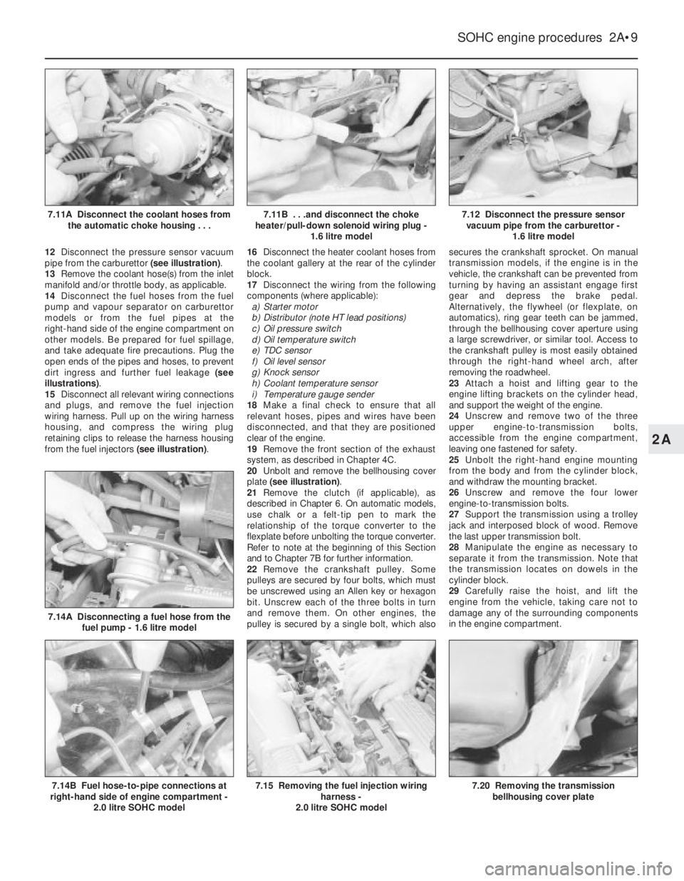
12Disconnect the pressure sensor vacuum
pipe from the carburettor (see illustration).
13Remove the coolant hose(s) from the inlet
manifold and/or throttle body, as applicable.
14Disconnect the fuel hoses from the fuel
pump and vapour separator on carburettor
models or from the fuel pipes at the
right-hand side of the engine compartment on
other models. Be prepared for fuel spillage,
and take adequate fire precautions. Plug the
open ends of the pipes and hoses, to prevent
dirt ingress and further fuel leakage (see
illustrations).
15Disconnect all relevant wiring connections
and plugs, and remove the fuel injection
wiring harness. Pull up on the wiring harness
housing, and compress the wiring plug
retaining clips to release the harness housing
from the fuel injectors (see illustration).16Disconnect the heater coolant hoses from
the coolant gallery at the rear of the cylinder
block.
17Disconnect the wiring from the following
components (where applicable):
a)Starter motor
b)Distributor (note HT lead positions)
c)Oil pressure switch
d)Oil temperature switch
e)TDC sensor
f)Oil level sensor
g)Knock sensor
h)Coolant temperature sensor
i)Temperature gauge sender
18Make a final check to ensure that all
relevant hoses, pipes and wires have been
disconnected, and that they are positioned
clear of the engine.
19Remove the front section of the exhaust
system, as described in Chapter 4C.
20Unbolt and remove the bellhousing cover
plate (see illustration).
21Remove the clutch (if applicable), as
described in Chapter 6. On automatic models,
use chalk or a felt-tip pen to mark the
relationship of the torque converter to the
flexplate before unbolting the torque converter.
Refer to note at the beginning of this Section
and to Chapter 7B for further information.
22Remove the crankshaft pulley. Some
pulleys are secured by four bolts, which must
be unscrewed using an Allen key or hexagon
bit. Unscrew each of the three bolts in turn
and remove them. On other engines, the
pulley is secured by a single bolt, which alsosecures the crankshaft sprocket. On manual
transmission models, if the engine is in the
vehicle, the crankshaft can be prevented from
turning by having an assistant engage first
gear and depress the brake pedal.
Alternatively, the flywheel (or flexplate, on
automatics), ring gear teeth can be jammed,
through the bellhousing cover aperture using
a large screwdriver, or similar tool. Access to
the crankshaft pulley is most easily obtained
through the right-hand wheel arch, after
removing the roadwheel.
23Attach a hoist and lifting gear to the
engine lifting brackets on the cylinder head,
and support the weight of the engine.
24Unscrew and remove two of the three
upper engine-to-transmission bolts,
accessible from the engine compartment,
leaving one fastened for safety.
25Unbolt the right-hand engine mounting
from the body and from the cylinder block,
and withdraw the mounting bracket.
26Unscrew and remove the four lower
engine-to-transmission bolts.
27Support the transmission using a trolley
jack and interposed block of wood. Remove
the last upper transmission bolt.
28Manipulate the engine as necessary to
separate it from the transmission. Note that
the transmission locates on dowels in the
cylinder block.
29Carefully raise the hoist, and lift the
engine from the vehicle, taking care not to
damage any of the surrounding components
in the engine compartment.
SOHC engine procedures 2A•9
7.12 Disconnect the pressure sensor
vacuum pipe from the carburettor -
1.6 litre model
7.20 Removing the transmission
bellhousing cover plate7.15 Removing the fuel injection wiring
harness -
2.0 litre SOHC model7.14B Fuel hose-to-pipe connections at
right-hand side of engine compartment -
2.0 litre SOHC model
7.14A Disconnecting a fuel hose from the
fuel pump - 1.6 litre model
7.11B . . .and disconnect the choke
heater/pull-down solenoid wiring plug -
1.6 litre model7.11A Disconnect the coolant hoses from
the automatic choke housing . . .
2A
Page 211 of 525

9The crankshaft pulley must now be
removed. On 1.4 and 1.6 litre engines (except
C 16 NZ2), the pulley is secured by a single
bolt, which also secures the crankshaft
sprocket. On C 16 NZ2, 1.8 and 2.0 litre
engines, the pulley is secured by four bolts,
which must be unscrewed using an Allen key
or hexagon bit. On manual transmission
models, if the engine is in the vehicle, the
crankshaft can be prevented from turning by
having an assistant engage first gear and
depress the brake pedal. Alternatively, the
flywheel ring gear teeth can be jammed using
a large screwdriver or similar tool.
10With the crankshaft pulley removed, the
timing belt can be withdrawn.
11If desired, the sprockets and the rear
timing belt cover can be removed as follows,
otherwise go on to paragraph 23.
12To remove the camshaft sprocket, firstdisconnect the breather hose(s) from the
camshaft cover, then unscrew the securing
bolts noting the locations of the HT lead
brackets and any other wiring brackets, and
remove the camshaft cover.
13Recover the gasket. Prevent the camshaft
from turning by holding it with a spanner on
the flats provided between No’s 3 and 4
camshaft lobes, and unscrew the camshaft
sprocket bolt.
14Withdraw the sprocket from the end of the
camshaft.
15To remove the crankshaft sprocket on 1.4
and 1.6 litre engines (except C 16 NZ2), if
necessary, remove the lower securing bolts
from the main rear timing belt cover and use
two large screwdrivers behind the cover to
lever off the sprocket. Remove the Woodruff
key if it is loose.
16To remove the crankshaft sprocket on C
16 NZ2, 1.8 and 2.0 litre engines, it will benecessary to prevent the crankshaft from
turning, as described in paragraph 9. Take
care when unscrewing the sprocket bolt, as it
is very tight. If necessary, use a two-legged
puller to remove the sprocket. Recover the
Woodruff key and the thrustwasher from the
end of the crankshaft.
17To remove the main rear timing belt cover
on C 16 NZ2, 1.8 and 2.0 litre models
disconnect the TDC sensor wiring plug and
unclip the wiring from the belt cover. Then
unscrew the two upper securing bolts and the
lower securing bolt(s) (one in the case of C 16
NZ2, 1.8 and 2.0 litre engines, two on other
SOHC engines). Withdraw the cover,
manipulating it from the smaller rear belt
cover on the coolant pump (see illustrations).
18If desired, the smaller rear belt cover can
be removed from the coolant pump, after
unscrewing the securing bolt (see
illustration), by rotating it to disengage it from
the retaining flange on the pump.
Refitting
19Refit the rear timing belt cover(s) using a
reversal of the removal procedure, and
ensuring that the main cover engages correctly
with the smaller cover on the coolant pump.
20On C 16 NZ2, 1.8 and 2.0 litre engines,
refit the thrustwasher and the Woodruff key to
the end of the crankshaft. Then refit the
crankshaft sprocket, and tighten the securing
bolt to the specified torque in the two stages
given in the Specifications. Ensure that the
washer is in place under the bolt head, and
prevent the crankshaft from turning as during
removal (see illustrations).
2A•14SOHC engine procedures
11.17A Loosening the main rear timing
belt cover lower securing bolt -
2.0 litre engine11.18 Unscrewing the coolant pump rear
belt cover securing bolt - 2.0 litre engine
11.20E Tighten the bolt to the specified
torque . . .11.20D . . .and the washer and bolt11.20C . . .the crankshaft sprocket . . .
11.20B . . . the Woodruff key . . .11.20A Refit the thrustwasher . . .
11.17B Main rear timing belt cover lower
securing bolts (arrowed) - 1.6 SV engine
Page 212 of 525
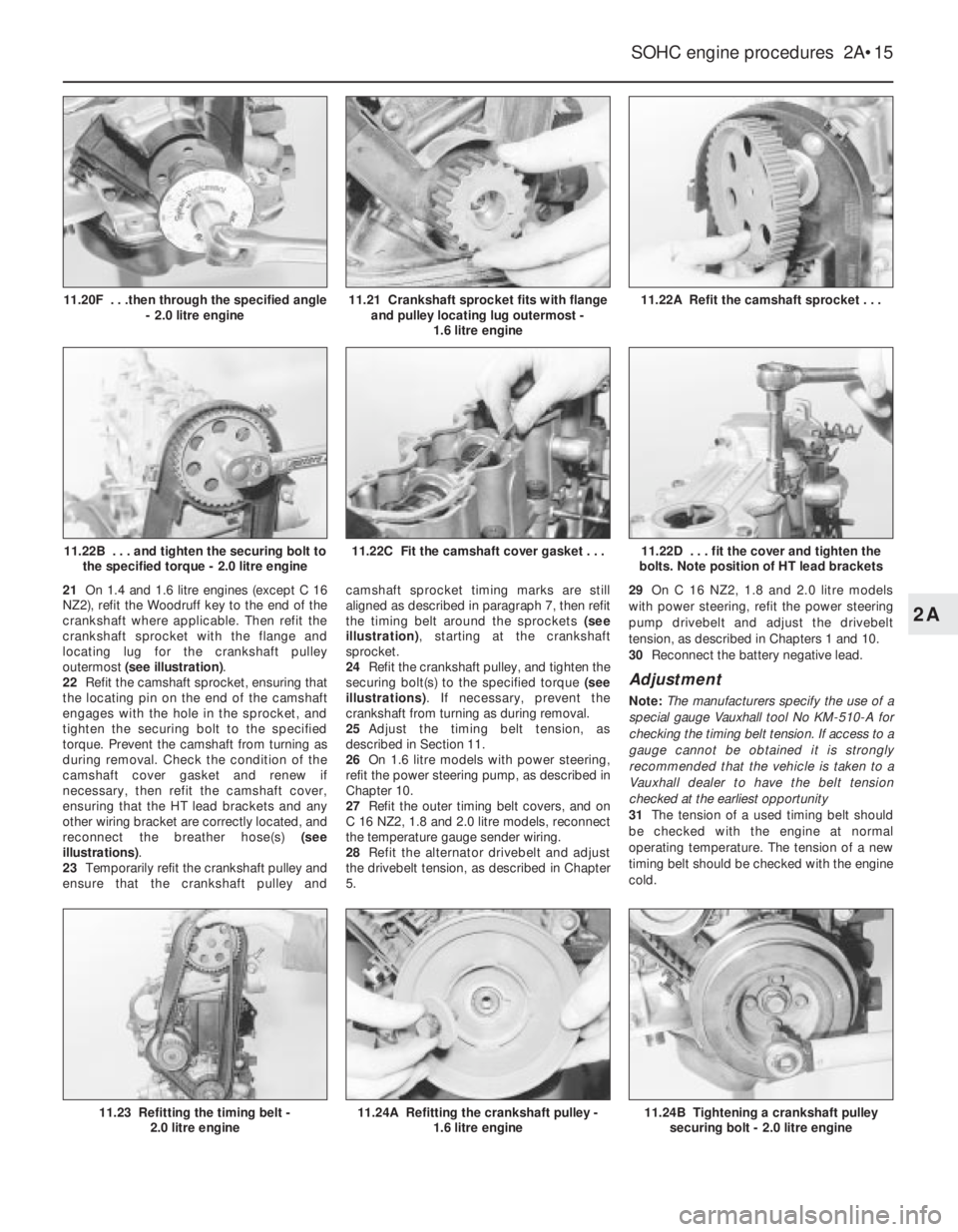
21On 1.4 and 1.6 litre engines (except C 16
NZ2), refit the Woodruff key to the end of the
crankshaft where applicable. Then refit the
crankshaft sprocket with the flange and
locating lug for the crankshaft pulley
outermost (see illustration).
22Refit the camshaft sprocket, ensuring that
the locating pin on the end of the camshaft
engages with the hole in the sprocket, and
tighten the securing bolt to the specified
torque. Prevent the camshaft from turning as
during removal. Check the condition of the
camshaft cover gasket and renew if
necessary, then refit the camshaft cover,
ensuring that the HT lead brackets and any
other wiring bracket are correctly located, and
reconnect the breather hose(s) (see
illustrations).
23Temporarily refit the crankshaft pulley and
ensure that the crankshaft pulley andcamshaft sprocket timing marks are still
aligned as described in paragraph 7, then refit
the timing belt around the sprockets (see
illustration), starting at the crankshaft
sprocket.
24Refit the crankshaft pulley, and tighten the
securing bolt(s) to the specified torque (see
illustrations). If necessary, prevent the
crankshaft from turning as during removal.
25Adjust the timing belt tension, as
described in Section 11.
26On 1.6 litre models with power steering,
refit the power steering pump, as described in
Chapter 10.
27Refit the outer timing belt covers, and on
C 16 NZ2, 1.8 and 2.0 litre models, reconnect
the temperature gauge sender wiring.
28Refit the alternator drivebelt and adjust
the drivebelt tension, as described in Chapter
5.29On C 16 NZ2, 1.8 and 2.0 litre models
with power steering, refit the power steering
pump drivebelt and adjust the drivebelt
tension, as described in Chapters 1 and 10.
30Reconnect the battery negative lead.
Adjustment
Note: The manufacturers specify the use of a
special gauge Vauxhall tool No KM-510-A for
checking the timing belt tension. If access to a
gauge cannot be obtained it is strongly
recommended that the vehicle is taken to a
Vauxhall dealer to have the belt tension
checked at the earliest opportunity
31The tension of a used timing belt should
be checked with the engine at normal
operating temperature. The tension of a new
timing belt should be checked with the engine
cold.
SOHC engine procedures 2A•15
11.22A Refit the camshaft sprocket . . .
11.24B Tightening a crankshaft pulley
securing bolt - 2.0 litre engine11.24A Refitting the crankshaft pulley -
1.6 litre engine11.23 Refitting the timing belt -
2.0 litre engine
11.22D . . . fit the cover and tighten the
bolts. Note position of HT lead brackets11.22C Fit the camshaft cover gasket . . .11.22B . . . and tighten the securing bolt to
the specified torque - 2.0 litre engine
11.21 Crankshaft sprocket fits with flange
and pulley locating lug outermost -
1.6 litre engine11.20F . . .then through the specified angle
- 2.0 litre engine
2A
Page 215 of 525
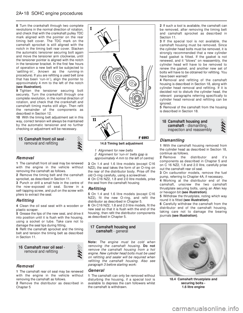
8Turn the crankshaft through two complete
revolutions in the normal direction of rotation,
and check that with the crankshaft pulley TDC
mark aligned with the pointer on the rear
timing belt cover. The TDC mark on the
camshaft sprocket is still aligned with the
notch in the timing belt rear cover. Slacken
the automatic tensioner securing bolt again
and move the tensioner arm clockwise, until
the tensioner pointer is aligned with the notch
in the tensioner bracket. In the first few hours
of operation a new belt will be subjected to
‘settling-in’, (known as the running-in
procedure). If you are refitting a used belt (one
that has been ‘run-in’), align the pointer to
approximately 4 mm to the left of the notch
(see illustration).
9Tighten the tensioner securing bolt
securely. Turn the crankshaft through one
complete revolution, in the normal direction of
rotation, and check that the crankshaft and
camshaft timing marks still align. Then refit
the remainder of the components as
described in Section 12.
10With the timing belt adjustment set in this
way, correct tension will always be maintained
by the automatic tensioner and no further
checking or adjustment will be necessary.
15Camshaft front oil seal -
removal and refitting
3
Removal
1The camshaft front oil seal may be renewed
with the engine in the vehicle without
removing the camshaft as follows.
2Remove the timing belt and the camshaft
sprocket, as described in Section 11.
3Punch or drill a small hole in the centre of
the now-exposed oil seal. Screw in a
self-tapping screw, and pull on the screw with
pliers to extract the seal.
Refitting
4Clean the oil seal seat with a wooden or
plastic scraper.
5Grease the lips of the new seal, and drive it
into position until it is flush with the housing,
using a socket or tube. Take care not to
damage the seal lips during fitting.
6Refit the camshaft sprocket and the timing
belt and tension the timing belt as described
in Section 11.
16Camshaft rear oil seal -
removal and refitting
3
Removal
1The camshaft rear oil seal may be renewed
with the engine in the vehicle without
removing the camshaft as follows.
2Remove the distributor as described in
Chapter 53On 1.4 and 1.6 litre models (except C16
NZ2), the seal takes the form of an O-ring on
the rear of the distributor body. Prise off the
old O-ring carefully, using a screwdriver.
4On C16 NZ2, 1.8 and 2.0 litre models, prise
the seal from the camshaft housing
Refitting
5 On 1.4 and 1.6 litre models (except C16
NZ2), fit the new O-ring, and refit the
distributor as described in Chapter 5.
6On C16 NZ2, 1.8 and 2.0 litre models, fit the
new seal so that it is flush with the end of the
housing, then refit the distributor components
as described in Chapter 5.
17Camshaft housing and
camshaft -general
Note: The engine must be cold when
removing the camshaft housing. Do not
remove the camshaft housing from a hot
engine. New cylinder head bolts must be used
on refitting and sealer will be required when
refitting the camshaft housing. Also see
paragraph 3 before starting work:
General
1The camshaft can only be removed without
disturbing the housing, if a special tool is
available to depress the cam followers whilst
the camshaft is withdrawn.2If such a tool is available, the camshaft can
be removed, after removing the timing belt
and camshaft sprocket as described in
Section 11.
3If the special tool is not available, the
camshaft housing must be removed. Since
the cylinder head bolts must be removed, it is
strongly recommended that a new cylinder
head gasket is fitted. If the gasket is not
renewed, and it “blows” on reassembly, the
cylinder head will have to be removed to
renew the gasket, and another new set of
bolts will have to be obtained for refitting. You
have been warned!
4Removal and refitting of the camshaft
housing is described in Section 18, along with
cylinder head removal and refitting. If it is
decided not to disturb the cylinder head, the
relevant paragraphs referring specifically to
cylinder head removal and refitting can be
ignored.
5Removal of the camshaft from the housing
is described in Section 18.
18Camshaft housing and
camshaft - dismantling,
inspection and reassembly
4
Dismantling
1With the camshaft housing removed from
the cylinder head as described in Section 18,
continue as follows.
2Remove the distributor and it’s
components as described in Chapter 5 and
on C 16 NZ2, 1.8 and 2.0 litre, carefully prise
out the camshaft rear oil seal.
3On carburettor models, remove the fuel
pump, referring to Chapter 4A, if necessary.
4Working at the distributor end of the
camshaft, unscrew the two camshaft
thrustplate securing bolts, using an Allen key
or hexagon bit (see illustration).
5Withdraw the thrustplate, noting which way
round it is fitted (see illustration).
6Carefully withdraw the camshaft from the
distributor end of the camshaft housing,
taking care not to damage the bearing
journals (see illustration).
2A•18SOHC engine procedures
14.8 Timing belt adjustment
1 Alignment for new belts
2 Alignment for ‘run-in’ belts (gap is
approximately 4 mm to the left of centre)
18.4 Camshaft thrustplate and
securing bolts -
1.6 litre engine
Page 223 of 525
25Flywheel -removal, inspection
and refitting
4
Note: New flywheel securing bolts must he
used on refitting. Certain models are fitted
with a ‘Pot type’ flywheel. Although, it has a
deeply recessed surface for the clutch disc,
the operations below are the same.
Removal
1If not already done, remove the clutch,
(Chapter 6), and the starter motor, (Chapter 5).
2If the engine is in the vehicle, remove the
clutch release bearing and its guide sleeve, as
described in Chapter 6.
3Although the flywheel bolt holes are offset
so that the flywheel can only be fitted in one
position, it will make refitting easier if
alignment marks are made between the
flywheel and the end of the crankshaft.
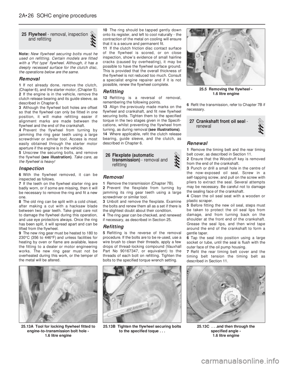
4Prevent the flywheel from turning by
jamming the ring gear teeth using a large
screwdriver or similar tool. Access is most
easily obtained through the starter motor
aperture if the engine is in the vehicle.
5Unscrew the securing bolts, and remove
the flywheel (see illustration). Take care, as
the flywheel is heavy!
Inspection
6With the flywheel removed, it can be
inspected as follows.
7If the teeth on the flywheel starter ring are
badly worn, or if some are missing, then it will
be necessary to remove the ring and fit a new
one.
8The old ring can be split with a cold chisel,
after making a cut with a hacksaw blade
between two gear teeth. Take great care not
to damage the flywheel during this operation,
and use eye protectors always. Once the ring
has been split, it will spread apart and can be
lifted from the flywheel.
9The new ring gear must be heated to 180 to
230°C (356 to 446°F) and unless facilities for
heating by oven or flame are available, leave
the fitting to a dealer or motor engineering
works. The new ring gear must not be
overheated during this work, or the temper of
the metal will be altered.10The ring should be tapped gently down
onto its register, and left to cool naturally -the
contraction of the metal on cooling will ensure
that it is a secure and permanent fit.
11If the clutch friction disc contact surface
of the flywheel is scored, or on close
inspection, show’s evidence of small hairline
cracks (caused by overheating), it may be
possible to have the flywheel surface ground.
This is provided that the overall thickness of
the flywheel is not reduced too much. Consult
a specialist engine repairer and if it is not
possible, renew the flywheel complete.
Refitting
12Refitting is a reversal of removal,
remembering the following points.
13Align the previously made marks on the
flywheel and crankshaft, and fit new flywheel
securing bolts. Tighten them to the specified
torque in the two stages given in the Specifi-
cations, whilst preventing the flywheel from
turning, as during removal (see illustrations).
14Where applicable, refit the clutch release
bearing, guide sleeve, and the clutch, as
described in Chapter 6.
26Flexplate (automatic
transmission) -removal and
refitting
4
Removal
1Remove the transmission (Chapter 7B).
2Prevent the flexplate from turning by
jamming its ring gear teeth using a large
screwdriver or similar tool.
3Unbolt and remove the flexplate. Examine
the bolts and renew them all as a set if there is
the slightest doubt about their condition.
4The ring gear can be checked, and renewed
if necessary, as described in Section 25.
Refitting
5Refitting is the reverse of the removal
procedure. If the bolts are to be re-used, use a
wire brush to clean their threads, apply a few
drops of thread-locking compound (Vauxhall
Part No 90167347, or equivalent) to the
threads of each bolt on refitting. Tighten the
bolts to the specified torque wrench setting.6Refit the transmission, refer to Chapter 7B if
necessary.
27Crankshaft front oil seal -
renewal
3
Renewal
1Remove the timing belt and the rear timing
belt cover, as described in Section 11.
2Ensure that the Woodruff key is removed
from the end of the crankshaft.
3Punch or drill a small hole in the centre of
the now-exposed oil seal. Screw in a
self-tapping screw, and pull on the screw with
pliers to extract the seal. Several attempts
may be necessary. Be careful not to damage
the sealing face of the crankshaft.
4Clean the oil seal seat with a wooden or
plastic scraper.
5Before fitting the new oil seal, steps must
be taken to protect the oil seal lips from
damage, and from turning back on the
shoulder at the front end of the crankshaft.
Grease the seal lips, and then wind tape
around the end of the crankshaft to form a
gentle taper.
6Tap the seal into position using a large
socket or tube, until the seal is flush with the
outer face of the oil pump housing.
7Refit the rear timing belt cover and the
timing belt tension the timing belt as
described in Section 11.
2A•26SOHC engine procedures
25.13C . . .and then through the
specified angle -
1.6 litre engine25.13B Tighten the flywheel securing bolts
to the specified toque . . .25.13A Tool for locking flywheel fitted to
engine-to-transmission bolt hole -
1.6 litre engine
25.5 Removing the flywheel -
1.6 litre engine
Page 242 of 525
Spare parts are available from many
sources, for example: Vauxhall dealers, other
garages and accessory shops, and motor
factors. Our advice regarding spare part
sources is as follows.
Officially appointed Vauxhall
dealers
This is the best source of parts that are
peculiar to your car and are otherwise not
generally available (e.g. complete cylinder
heads, transmission components, badges,
interior trim, etc.). It is also the only place at
which you should buy parts if your vehicle is
still under warranty -use of non-Vauxhall
components may invalidate the warranty. To
be sure of obtaining the correct parts it willalways be necessary to give the storeman
your car’s vehicle identification number, and if
possible, to take the “old” parts along for
positive identification. Remember that many
parts are available on a factory exchange
scheme -any parts returned should always be
clean! It obviously makes good sense to go
straight to the specialists on your car for this
type of part for they are best equipped to
supply you.
Other garages and accessory
shops
These are often very good places to buy
materials and components needed for the
maintenance of your car (e.g. oil filters, spark
plugs, bulbs, drivebelts, oils and greases,touch-up paint, filler paste, etc.). They also
sell general accessories, usually have
convenient opening hours, charge lower
prices and can often be found not far from
home.
Motor factors
Good factors will stock all the more
important components that wear out
relatively quickly (e.g. clutch components,
pistons, valves, exhaust systems, brake
cylinders/pipes/hoses/seals/shoes and pads,
etc.). Motor factors will often provide new or
reconditioned components on a part
exchange basis -this can save considerable
amount of money.
Modifications are a continuing and
unpublished process in vehicle manufacture,
quite apart from major model changes. Spare
parts manuals and lists are compiled upon a
numerical basis, the individual vehicle
numbers being essential to correct identifi-
cation of the component required.
When ordering spare parts, always give as
much information as possible. Quote the car
model, year of manufacture and vehicle iden-
tification and/or engine numbers as
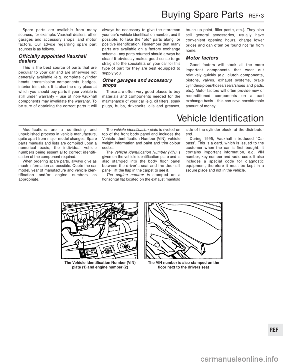
appropriate.The vehicle identification plate is riveted on
top of the front body panel and includes the
Vehicle Identification Number (VIN), vehicle
weight information and paint and trim colour
codes.
The Vehicle Identification Number (VIN) is
given on the vehicle identification plate and is
also stamped into the body floor panel
between the driver’s seat and the door sill
panel; lift the flap in the carpet to see it.
The engine number is stamped on a
horizontal flat located on the exhaust manifoldside of the cylinder block, at the distributor
end.
During 1995, Vauxhall introduced ‘Car
pass’. This is a card, which is issued to the
customer when the car is first bought. It
contains important information, e.g. VIN
number, key number and radio code. It also
includes a special code for diagnostic
equipment, therefore it must be kept in a
secure place and not in the vehicle.
Buying Spare Parts REF•3
The VIN number is also stamped on the
floor next to the drivers seatThe Vehicle Identification Number (VIN)
plate (1) and engine number (2)
REF
Vehicle Identification
Page 245 of 525
REF•6Tools and Working Facilities
Introduction
A selection of good tools is a fundamental
requirement for anyone contemplating the
maintenance and repair of a motor vehicle.
For the owner who does not possess any,
their purchase will prove a considerable
expense, offsetting some of the savings made
by doing-it-yourself. However, provided that
the tools purchased meet the relevant national
safety standards and are of good quality, they
will last for many years and prove an
extremely worthwhile investment.
To help the average owner to decide which
tools are needed to carry out the various tasks
detailed in this manual, we have compiled
three lists of tools under the following
headings: Maintenance and minor repair,
Repair and overhaul, and Special. Newcomers
to practical mechanics should start off with
the Maintenance and minor repairtool kit, and
confine themselves to the simpler jobs around
the vehicle. Then, as confidence and
experience grow, more difficult tasks can be
undertaken, with extra tools being purchased
as, and when, they are needed. In this way, a
Maintenance and minor repairtool kit can be
built up into a Repair and overhaultool kit over
a considerable period of time, without any
major cash outlays. The experienced do-it-
yourselfer will have a tool kit good enough for
most repair and overhaul procedures, and will
add tools from the Specialcategory when it is
felt that the expense is justified by the amount
of use to which these tools will be put.
Maintenance
and minor repair tool kit
The tools given in this list should be
considered as a minimum requirement if
routine maintenance, servicing and minor
repair operations are to be undertaken. We
recommend the purchase of combination
spanners (ring one end, open-ended the
other); although more expensive than open-
ended ones, they do give the advantages of
both types of spanner.
MCombination spanners:
Metric - 8 to 19 mm inclusive
MAdjustable spanner - 35 mm jaw (approx.)
MSpark plug spanner (with rubber insert) -
petrol models
MSpark plug gap adjustment tool - petrol
models
MSet of feeler gauges
MBrake bleed nipple spanner
MScrewdrivers:
Flat blade - 100 mm long x 6 mm dia
Cross blade - 100 mm long x 6 mm dia
MCombination pliers
MHacksaw (junior)
MTyre pump
MTyre pressure gauge
MOil can
MOil filter removal tool
MFine emery cloth
MWire brush (small)
MFunnel (medium size)
Repair and overhaul tool kit
These tools are virtually essential for
anyone undertaking any major repairs to a
motor vehicle, and are additional to those
given in the Maintenance and minor repairlist.
Included in this list is a comprehensive set of
sockets. Although these are expensive, they
will be found invaluable as they are so
versatile - particularly if various drives are
included in the set. We recommend the half-
inch square-drive type, as this can be used
with most proprietary torque wrenches.
The tools in this list will sometimes need to
be supplemented by tools from the Speciallist:
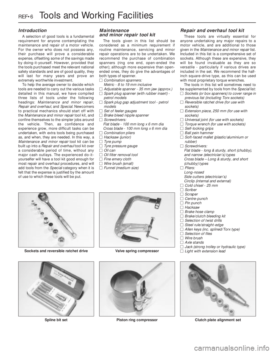
MSockets (or box spanners) to cover range in
previous list (including Torx sockets)
MReversible ratchet drive (for use with
sockets)
MExtension piece, 250 mm (for use with
sockets)
MUniversal joint (for use with sockets)
MTorque wrench (for use with sockets)
MSelf-locking grips
MBall pein hammer
MSoft-faced mallet (plastic/aluminium or
rubber)
MScrewdrivers:
Flat blade - long & sturdy, short (chubby),
and narrow (electrician’s) types
Cross blade – Long & sturdy, and short
(chubby) types
MPliers:
Long-nosed
Side cutters (electrician’s)
Circlip (internal and external)
MCold chisel - 25 mm
MScriber
MScraper
MCentre-punch
MPin punch
MHacksaw
MBrake hose clamp
MBrake/clutch bleeding kit
MSelection of twist drills
MSteel rule/straight-edge
MAllen keys (inc. splined/Torx type)
MSelection of files
MWire brush
MAxle stands
MJack (strong trolley or hydraulic type)
MLight with extension lead
Sockets and reversible ratchet drive
Clutch plate alignment setPiston ring compressorSpline bit set
Valve spring compressor