1988 OPEL CALIBRA fuel type
[x] Cancel search: fuel typePage 168 of 525
4B
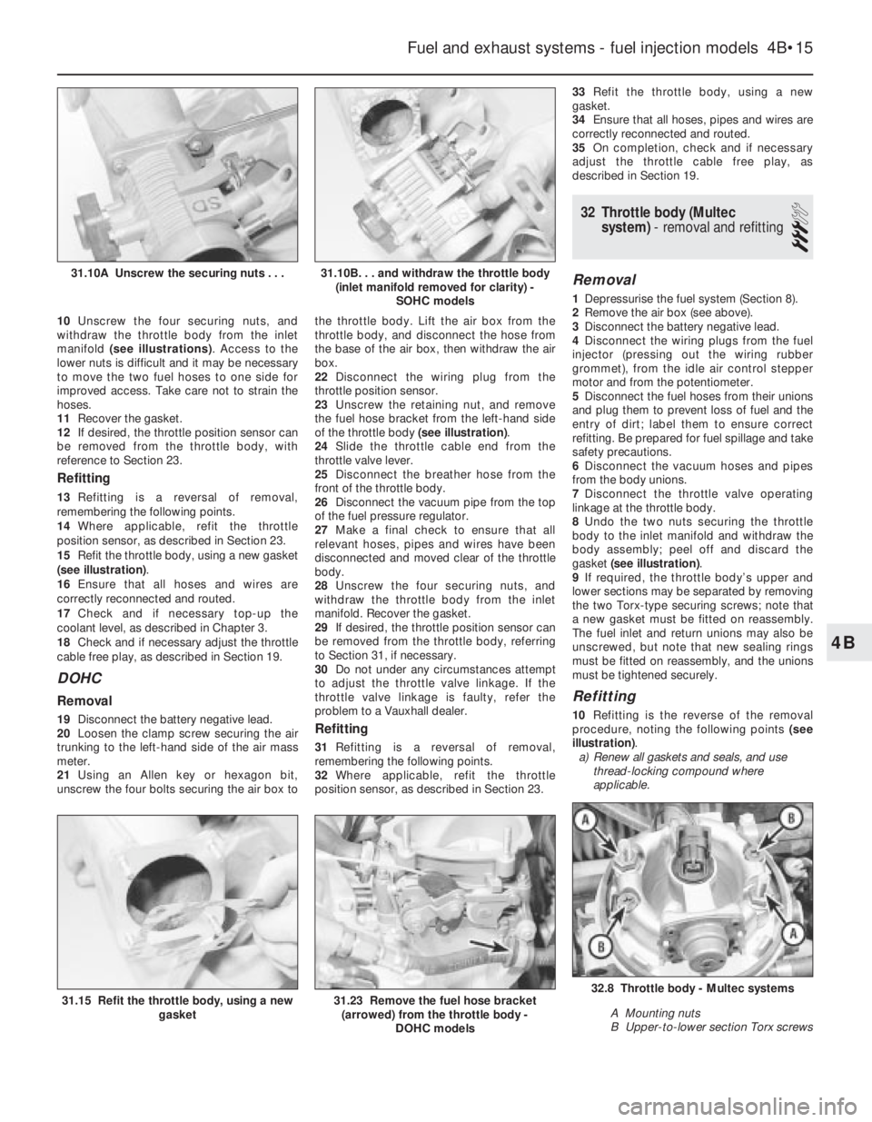
10Unscrew the four securing nuts, and
withdraw the throttle body from the inlet
manifold (see illustrations). Access to the
lower nuts is difficult and it may be necessary
to move the two fuel hoses to one side for
improved access. Take care not to strain the
hoses.
11Recover the gasket.
12If desired, the throttle position sensor can
be removed from the throttle body, with
reference to Section 23.
Refitting
13Refitting is a reversal of removal,
remembering the following points.
14Where applicable, refit the throttle
position sensor, as described in Section 23.
15Refit the throttle body, using a new gasket
(see illustration).
16Ensure that all hoses and wires are
correctly reconnected and routed.
17Check and if necessary top-up the
coolant level, as described in Chapter 3.
18Check and if necessary adjust the throttle
cable free play, as described in Section 19.
DOHC
Removal
19Disconnect the battery negative lead.
20Loosen the clamp screw securing the air
trunking to the left-hand side of the air mass
meter.
21Using an Allen key or hexagon bit,
unscrew the four bolts securing the air box tothe throttle body. Lift the air box from the
throttle body, and disconnect the hose from
the base of the air box, then withdraw the air
box.
22Disconnect the wiring plug from the
throttle position sensor.
23Unscrew the retaining nut, and remove
the fuel hose bracket from the left-hand side
of the throttle body (see illustration).
24Slide the throttle cable end from the
throttle valve lever.
25Disconnect the breather hose from the
front of the throttle body.
26Disconnect the vacuum pipe from the top
of the fuel pressure regulator.
27Make a final check to ensure that all
relevant hoses, pipes and wires have been
disconnected and moved clear of the throttle
body.
28Unscrew the four securing nuts, and
withdraw the throttle body from the inlet
manifold. Recover the gasket.
29If desired, the throttle position sensor can
be removed from the throttle body, referring
to Section 31, if necessary.
30Do not under any circumstances attempt
to adjust the throttle valve linkage. If the
throttle valve linkage is faulty, refer the
problem to a Vauxhall dealer.Refitting
31Refitting is a reversal of removal,
remembering the following points.
32Where applicable, refit the throttle
position sensor, as described in Section 23. 33Refit the throttle body, using a new
gasket.
34Ensure that all hoses, pipes and wires are
correctly reconnected and routed.
35On completion, check and if necessary
adjust the throttle cable free play, as
described in Section 19.
32Throttle body (Multec
system) - removal and refitting
3
Removal
1Depressurise the fuel system (Section 8).
2Remove the air box (see above).
3Disconnect the battery negative lead.
4Disconnect the wiring plugs from the fuel
injector (pressing out the wiring rubber
grommet), from the idle air control stepper
motor and from the potentiometer.
5Disconnect the fuel hoses from their unions
and plug them to prevent loss of fuel and the
entry of dirt; label them to ensure correct
refitting. Be prepared for fuel spillage and take
safety precautions.
6Disconnect the vacuum hoses and pipes
from the body unions.
7Disconnect the throttle valve operating
linkage at the throttle body.
8Undo the two nuts securing the throttle
body to the inlet manifold and withdraw the
body assembly; peel off and discard the
gasket (see illustration).
9If required, the throttle body’s upper and
lower sections may be separated by removing
the two Torx-type securing screws; note that
a new gasket must be fitted on reassembly.
The fuel inlet and return unions may also be
unscrewed, but note that new sealing rings
must be fitted on reassembly, and the unions
must be tightened securely.
Refitting
10Refitting is the reverse of the removal
procedure, noting the following points (see
illustration).
a)Renew all gaskets and seals, and use
thread-locking compound where
applicable.
Fuel and exhaust systems - fuel injection models 4B•15
31.15 Refit the throttle body, using a new
gasket32.8 Throttle body - Multec systems
A Mounting nuts
B Upper-to-lower section Torx screws31.23 Remove the fuel hose bracket
(arrowed) from the throttle body -
DOHC models
31.10B. . . and withdraw the throttle body
(inlet manifold removed for clarity) -
SOHC models31.10A Unscrew the securing nuts . . .
Page 169 of 525
b)Check the throttle cable operation and
adjustment (see above).
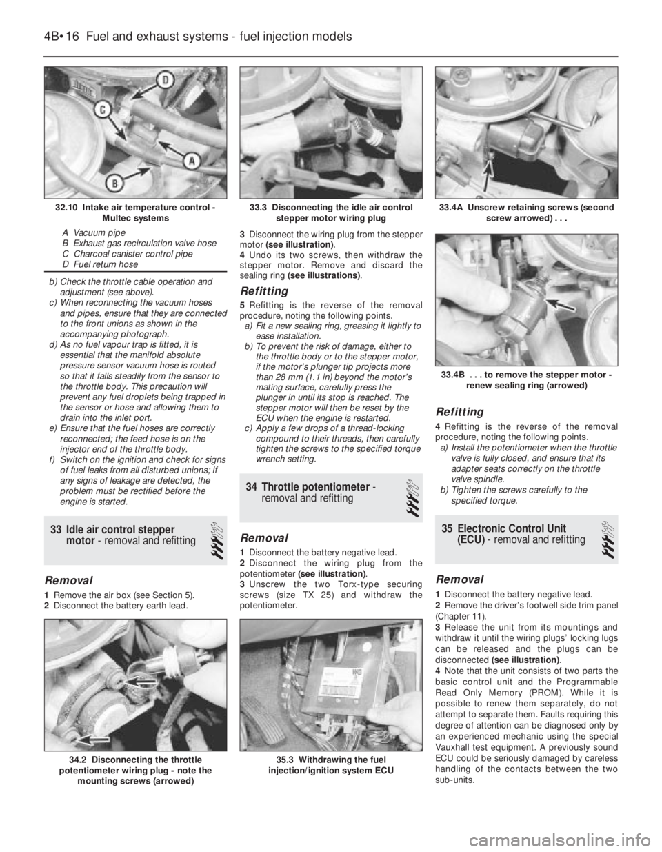
c)When reconnecting the vacuum hoses
and pipes, ensure that they are connected
to the front unions as shown in the
accompanying photograph.
d)As no fuel vapour trap is fitted, it is
essential that the manifold absolute
pressure sensor vacuum hose is routed
so that it falls steadily from the sensor to
the throttle body. This precaution will
prevent any fuel droplets being trapped in
the sensor or hose and allowing them to
drain into the inlet port.
e)Ensure that the fuel hoses are correctly
reconnected; the feed hose is on the
injector end of the throttle body.
f)Switch on the ignition and check for signs
of fuel leaks from all disturbed unions; if
any signs of leakage are detected, the
problem must be rectified before the
engine is started.
33Idle air control stepper
motor - removal and refitting
3
Removal
1Remove the air box (see Section 5).
2Disconnect the battery earth lead.3Disconnect the wiring plug from the stepper
motor (see illustration).
4Undo its two screws, then withdraw the
stepper motor. Remove and discard the
sealing ring (see illustrations).
Refitting
5Refitting is the reverse of the removal
procedure, noting the following points.
a)Fit a new sealing ring, greasing it lightly to
ease installation.
b)To prevent the risk of damage, either to
the throttle body or to the stepper motor,
if the motor’s plunger tip projects more
than 28 mm (1.1 in) beyond the motor’s
mating surface, carefully press the
plunger in until its stop is reached. The
stepper motor will then be reset by the
ECU when the engine is restarted.
c)Apply a few drops of a thread-locking
compound to their threads, then carefully
tighten the screws to the specified torque
wrench setting.
34Throttle potentiometer -
removal and refitting
3
Removal
1Disconnect the battery negative lead.
2Disconnect the wiring plug from the
potentiometer (see illustration).
3Unscrew the two Torx-type securing
screws (size TX 25) and withdraw the
potentiometer.
Refitting
4Refitting is the reverse of the removal
procedure, noting the following points.
a)Install the potentiometer when the throttle
valve is fully closed, and ensure that its
adapter seats correctly on the throttle
valve spindle.
b)Tighten the screws carefully to the
specified torque.
35Electronic Control Unit
(ECU) - removal and refitting
3
Removal
1Disconnect the battery negative lead.
2Remove the driver’s footwell side trim panel
(Chapter 11).
3Release the unit from its mountings and
withdraw it until the wiring plugs’ locking lugs
can be released and the plugs can be
disconnected (see illustration).
4Note that the unit consists of two parts the
basic control unit and the Programmable
Read Only Memory (PROM). While it is
possible to renew them separately, do not
attempt to separate them. Faults requiring this
degree of attention can be diagnosed only by
an experienced mechanic using the special
Vauxhall test equipment. A previously sound
ECU could be seriously damaged by careless
handling of the contacts between the two
sub-units.
4B•16Fuel and exhaust systems - fuel injection models
32.10 Intake air temperature control -
Multec systems
A Vacuum pipe
B Exhaust gas recirculation valve hose
C Charcoal canister control pipe
D Fuel return hose
33.4A Unscrew retaining screws (second
screw arrowed) . . .
35.3 Withdrawing the fuel
injection/ignition system ECU34.2 Disconnecting the throttle
potentiometer wiring plug - note the
mounting screws (arrowed)
33.4B . . . to remove the stepper motor -
renew sealing ring (arrowed)
33.3 Disconnecting the idle air control
stepper motor wiring plug
Page 174 of 525
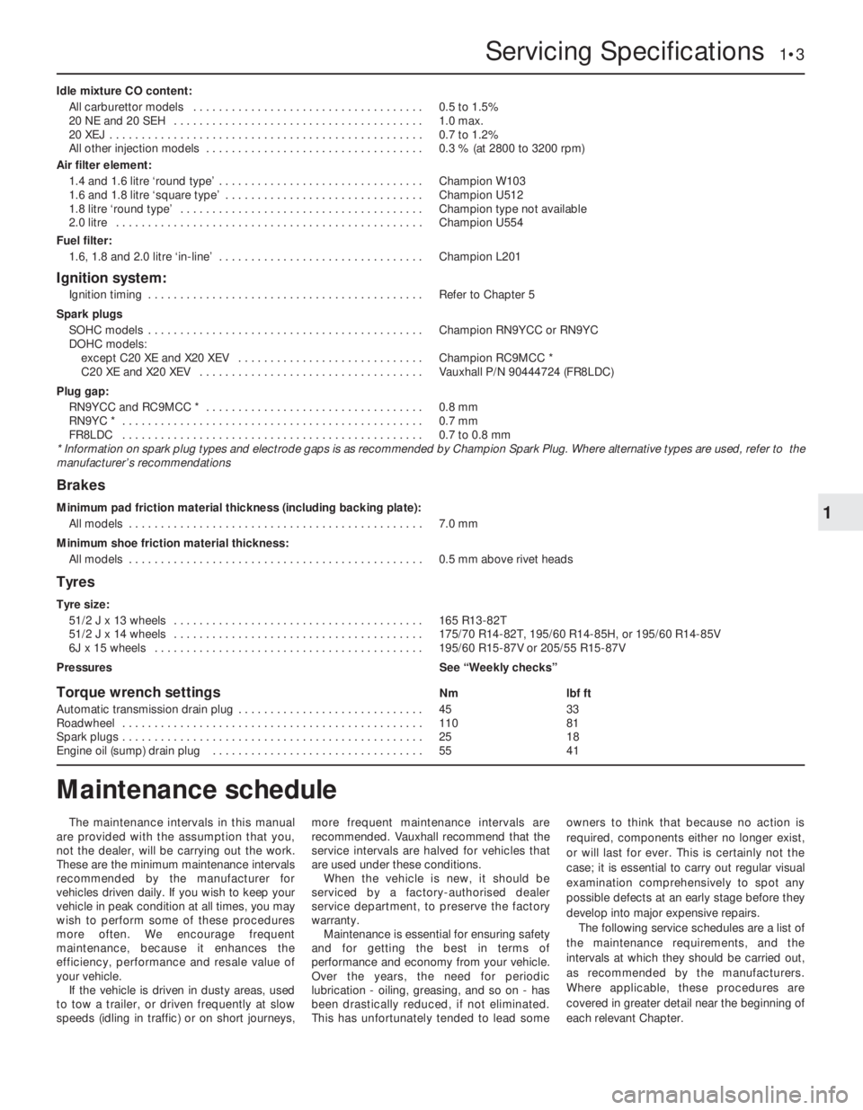
Idle mixture CO content:
All carburettor models . . . . . . . . . . . . . . . . . . . . . . . . . . . . . . . . . . . .0.5 to 1.5%
20 NE and 20 SEH . . . . . . . . . . . . . . . . . . . . . . . . . . . . . . . . . . . . . . .1.0 max.
20 XEJ . . . . . . . . . . . . . . . . . . . . . . . . . . . . . . . . . . . . . . . . . . . . . . . . .0.7 to 1.2%
All other injection models . . . . . . . . . . . . . . . . . . . . . . . . . . . . . . . . . .0.3 % (at 2800 to 3200 rpm)
Air filter element:
1.4 and 1.6 litre ‘round type’ . . . . . . . . . . . . . . . . . . . . . . . . . . . . . . . .Champion W103
1.6 and 1.8 litre ‘square type’ . . . . . . . . . . . . . . . . . . . . . . . . . . . . . . .Champion U512
1.8 litre ‘round type’ . . . . . . . . . . . . . . . . . . . . . . . . . . . . . . . . . . . . . .Champion type not available
2.0 litre . . . . . . . . . . . . . . . . . . . . . . . . . . . . . . . . . . . . . . . . . . . . . . . .Champion U554
Fuel filter:
1.6, 1.8 and 2.0 litre ‘in-line’ . . . . . . . . . . . . . . . . . . . . . . . . . . . . . . . .Champion L201
Ignition system:
Ignition timing . . . . . . . . . . . . . . . . . . . . . . . . . . . . . . . . . . . . . . . . . . .Refer to Chapter 5
Spark plugs
SOHC models . . . . . . . . . . . . . . . . . . . . . . . . . . . . . . . . . . . . . . . . . . .Champion RN9YCC or RN9YC
DOHC models:
except C20 XE and X20 XEV . . . . . . . . . . . . . . . . . . . . . . . . . . . . .Champion RC9MCC *
C20 XE and X20 XEV . . . . . . . . . . . . . . . . . . . . . . . . . . . . . . . . . . .Vauxhall P/N 90444724 (FR8LDC)
Plug gap:
RN9YCC and RC9MCC * . . . . . . . . . . . . . . . . . . . . . . . . . . . . . . . . . .0.8 mm
RN9YC * . . . . . . . . . . . . . . . . . . . . . . . . . . . . . . . . . . . . . . . . . . . . . . .0.7 mm
FR8LDC . . . . . . . . . . . . . . . . . . . . . . . . . . . . . . . . . . . . . . . . . . . . . . .0.7 to 0.8 mm
* Information on spark plug types and electrode gaps is as recommended by Champion Spark Plug. Where alternative types are used, refer to the
manufacturer’s recommendations
Brakes
Minimum pad friction material thickness (including backing plate):
All models . . . . . . . . . . . . . . . . . . . . . . . . . . . . . . . . . . . . . . . . . . . . . .7.0 mm
Minimum shoe friction material thickness:
All models . . . . . . . . . . . . . . . . . . . . . . . . . . . . . . . . . . . . . . . . . . . . . .0.5 mm above rivet heads
Tyres
Tyre size:
51/2 J x 13 wheels . . . . . . . . . . . . . . . . . . . . . . . . . . . . . . . . . . . . . . .165 R13-82T
51/2 J x 14 wheels . . . . . . . . . . . . . . . . . . . . . . . . . . . . . . . . . . . . . . .175/70 R14-82T, 195/60 R14-85H, or 195/60 R14-85V
6J x 15 wheels . . . . . . . . . . . . . . . . . . . . . . . . . . . . . . . . . . . . . . . . . .195/60 R15-87V or 205/55 R15-87V
PressuresSee “Weekly checks”
Torque wrench settingsNmlbf ft
Automatic transmission drain plug . . . . . . . . . . . . . . . . . . . . . . . . . . . . .4533
Roadwheel . . . . . . . . . . . . . . . . . . . . . . . . . . . . . . . . . . . . . . . . . . . . . . .11081
Spark plugs . . . . . . . . . . . . . . . . . . . . . . . . . . . . . . . . . . . . . . . . . . . . . . .2518
Engine oil (sump) drain plug . . . . . . . . . . . . . . . . . . . . . . . . . . . . . . . . .5541
Servicing Specifications 1•3
1
The maintenance intervals in this manual
are provided with the assumption that you,
not the dealer, will be carrying out the work.
These are the minimum maintenance intervals
recommended by the manufacturer for
vehicles driven daily. If you wish to keep your
vehicle in peak condition at all times, you may
wish to perform some of these procedures
more often. We encourage frequent
maintenance, because it enhances the
efficiency, performance and resale value of
your vehicle.
If the vehicle is driven in dusty areas, used
to tow a trailer, or driven frequently at slow
speeds (idling in traffic) or on short journeys,more frequent maintenance intervals are
recommended. Vauxhall recommend that the
service intervals are halved for vehicles that
are used under these conditions.
When the vehicle is new, it should be
serviced by a factory-authorised dealer
service department, to preserve the factory
warranty.
Maintenance is essential for ensuring safety
and for getting the best in terms of
performance and economy from your vehicle.
Over the years, the need for periodic
lubrication -oiling, greasing, and so on -has
been drastically reduced, if not eliminated.
This has unfortunately tended to lead someowners to think that because no action is
required, components either no longer exist,
or will last for ever. This is certainly not the
case; it is essential to carry out regular visual
examination comprehensively to spot any
possible defects at an early stage before they
develop into major expensive repairs.
The following service schedules are a list of
the maintenance requirements, and the
intervals at which they should be carried out,
as recommended by the manufacturers.
Where applicable, these procedures are
covered in greater detail near the beginning of
each relevant Chapter.
Maintenance schedule
Page 176 of 525
Maintenance - component location 1•5
1
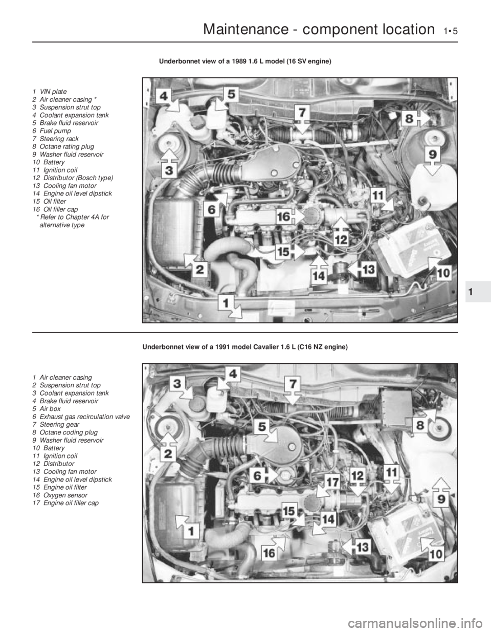
Underbonnet view of a 1989 1.6 L model (16 SV engine)
1 VIN plate
2 Air cleaner casing *
3 Suspension strut top
4 Coolant expansion tank
5 Brake fluid reservoir
6 Fuel pump
7 Steering rack
8 Octane rating plug
9 Washer fluid reservoir
10 Battery
11 Ignition coil
12 Distributor (Bosch type)
13 Cooling fan motor
14 Engine oil level dipstick
15 Oil filter
16 Oil filler cap
* Refer to Chapter 4A for
alternative type
Underbonnet view of a 1991 model Cavalier 1.6 L (C16 NZ engine)
1 Air cleaner casing
2 Suspension strut top
3 Coolant expansion tank
4 Brake fluid reservoir
5 Air box
6 Exhaust gas recirculation valve
7 Steering gear
8 Octane coding plug
9 Washer fluid reservoir
10 Battery
11 Ignition coil
12 Distributor
13 Cooling fan motor
14 Engine oil level dipstick
15 Engine oil filter
16 Oxygen sensor
17 Engine oil filler cap
Page 185 of 525
28Air inlet temperature control
check (carburettor models
only)
2
Refer to Chapter 4A for details.
29Fuel filter renewal
3
Fuel filters are fitted in various locations
throughout the range. Some may be ‘in-line’ in
the fuel tank itself, or fitted into the
carburettor.
Refer to Chapters 4A or 4B, as appropriate.
30Spark plug renewal (SOHC)
2
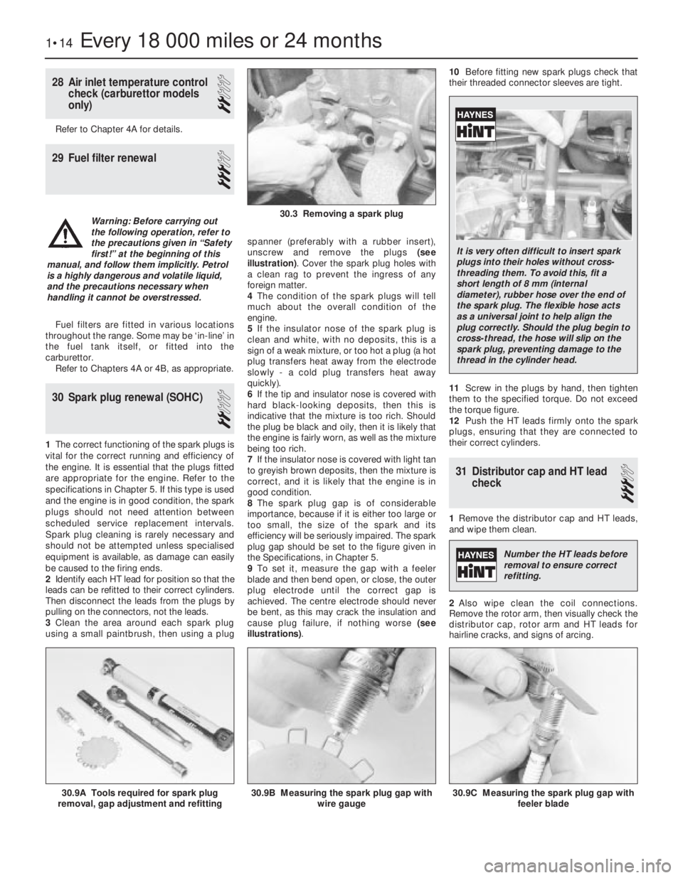
1The correct functioning of the spark plugs is
vital for the correct running and efficiency of
the engine. It is essential that the plugs fitted
are appropriate for the engine. Refer to the
specifications in Chapter 5. If this type is used
and the engine is in good condition, the spark
plugs should not need attention between
scheduled service replacement intervals.
Spark plug cleaning is rarely necessary and
should not be attempted unless specialised
equipment is available, as damage can easily
be caused to the firing ends.
2Identify each HT lead for position so that the
leads can be refitted to their correct cylinders.
Then disconnect the leads from the plugs by
pulling on the connectors, not the leads.
3Clean the area around each spark plug
using a small paintbrush, then using a plugspanner (preferably with a rubber insert),
unscrew and remove the plugs (see
illustration). Cover the spark plug holes with
a clean rag to prevent the ingress of any
foreign matter.
4The condition of the spark plugs will tell
much about the overall condition of the
engine.
5If the insulator nose of the spark plug is
clean and white, with no deposits, this is a
sign of a weak mixture, or too hot a plug (a hot
plug transfers heat away from the electrode
slowly -a cold plug transfers heat away
quickly).
6If the tip and insulator nose is covered with
hard black-looking deposits, then this is
indicative that the mixture is too rich. Should
the plug be black and oily, then it is likely that
the engine is fairly worn, as well as the mixture
being too rich.
7If the insulator nose is covered with light tan
to greyish brown deposits, then the mixture is
correct, and it is likely that the engine is in
good condition.
8The spark plug gap is of considerable
importance, because if it is either too large or
too small, the size of the spark and its
efficiency will be seriously impaired. The spark
plug gap should be set to the figure given in
the Specifications, in Chapter 5.
9To set it, measure the gap with a feeler
blade and then bend open, or close, the outer
plug electrode until the correct gap is
achieved. The centre electrode should never
be bent, as this may crack the insulation and
cause plug failure, if nothing worse (see
illustrations).10Before fitting new spark plugs check that
their threaded connector sleeves are tight.
11Screw in the plugs by hand, then tighten
them to the specified torque. Do not exceed
the torque figure.
12Push the HT leads firmly onto the spark
plugs, ensuring that they are connected to
their correct cylinders.
31Distributor cap and HT lead
check
3
1Remove the distributor cap and HT leads,
and wipe them clean.
2Also wipe clean the coil connections.
Remove the rotor arm, then visually check the
distributor cap, rotor arm and HT leads for
hairline cracks, and signs of arcing.
1•14Every 18 000 miles or 24 months
30.9A Tools required for spark plug
removal, gap adjustment and refitting30.9C Measuring the spark plug gap with
feeler blade30.9B Measuring the spark plug gap with
wire gauge
30.3 Removing a spark plugWarning: Before carrying out
the following operation, refer to
the precautions given in “Safety
first!” at the beginning of this
manual, and follow them implicitly. Petrol
is a highly dangerous and volatile liquid,
and the precautions necessary when
handling it cannot be overstressed.
It is very often difficult to insert spark
plugs into their holes without cross-
threading them. To avoid this, fit a
short length of 8 mm (internal
diameter), rubber hose over the end of
the spark plug. The flexible hose acts
as a universal joint to help align the
plug correctly. Should the plug begin to
cross-thread, the hose will slip on the
spark plug, preventing damage to the
thread in the cylinder head.
Number the HT leads before
removal to ensure correct
refitting.
Page 194 of 525
pitting. If evident, the cylinder head and all
bearing caps must be renewed as a matched
set, as there is no provision for refacing if the
bearing caps cannot be renewed individually.
8The camshaft(s) should show no marks or
scoring on the journal or cam lobe surfaces. if
evident, renew the camshaft(s).
9It is advisable to renew the camshaft front
oil seal(s) as a matter of course. Prise the old
seal(s) from the front of the camshaft(s) and
discard them.
Refitting
10Begin refitting by liberally coating the
contact faces of the hydraulic valve lifters and
the camshaft(s) with molybdenum disulphide
paste.
11Coat the mating faces of the front and
rear bearing caps with sealing compound and
refit the bearing caps in their original positions
as noted during removal.
12Tighten the camshaft bearing cap nuts to
the specified torque in half-turn stages, as
when loosening the nuts. Note that when
refitting the exhaust camshaft, the two smaller
rear bearing cap securing nuts should be
tightened after all the main camshaft bearing
cap nuts have been tightened. Note also that
the two smaller nuts should be tightened to a
lower torque wrench setting than the main
nuts.
13Turn the camshaft until the locating peg
for the camshaft sprocket is uppermost, then
lubricate the lips of a rear camshaft front oil
seal with a little grease, and fit the oil seal,
using a tube or socket of similar diameter with
a washer and the camshaft sprocket bolt.
Screw the camshaft sprocket bolt into the end
of the camshaft to draw the oil seal into
position on its shoulder.
14Repeat the procedure for the remaining
camshaft.
15Refit the distributor with reference to
Chapter 5. Fit a new timing belt and the
camshaft sprockets, then adjust the timing
belt as described in Section 4 or 5, as
applicable.
8Cylinder head -removal and
refitting (engine in vehicle)
4
Note: The engine must be cold when the
cylinder head is removed. Do not remove the
cylinder head from a hot engine. New cylinder
head bolts, a new cylinder head gasket and a
new timing belt must be used on refitting.
The torque settings (as shown in Chapter 2A)
are only applicable to latest specification head
bolts, available from Vauxhall. Earlier type or
alternative make, head bolts may require
different torques. Consult your supplier
Removal
1Disconnect the battery negative lead.
2Drain the cooling system, as described in
Chapter 3.3Remove the front section of the exhaust
system, as described in Chapter 4C.
4The cylinder head can be removed
complete with the inlet manifold, or the inlet
manifold can be detached from the cylinder
head before removal, with reference to
Chapter 4B. If no work is to be carried out on
the inlet manifold, it can be unbolted from the
cylinder head and supported to one side out
of the way, thus avoiding the need to
disconnect the relevant hoses, pipes and
wiring.
5If the cylinder head is to be removed
complete with the inlet manifold, disconnect
all relevant hoses, pipes and wiring from the
inlet manifold and associated components,
referring to Chapter 4B, and unbolt the
manifold support bracket from the manifold.
Loosen the alternator mountings with
reference to Chapter 5, then unbolt the upper
alternator mounting from the inlet manifold.
6If the inlet manifold is to be left in the engine
compartment, continue as follows, otherwise
go on to paragraph 17.
7Disconnect the wiring plug from the airflow
meter, and the breather hose from the air box
on the throttle body. Disconnect the air
cleaner trunking and remove the airflow
meter/air box assembly from the throttle
body. Refer to Chapter 4B if necessary.
8Disconnect the end of the throttle cable
from the throttle valve lever, then unbolt the
throttle cable support bracket and remove it
from the inlet manifold.
9Unscrew the two earth lead securing nuts
from the fuel rail (one at each end of the rail)
and disconnect the three earth leads.
10Disconnect the wiring plug from the
throttle position switch.
11Pull up on the wiring harness housing, and
disconnect the wiring plugs from the fuel
injectors by compressing the retaining clips.
Move the wiring harness housing to one side.
12Disconnect the two breather hoses from
the rear of the camshaft cover.
13Loosen the alternator mountings, with
reference to Chapter 5, then unbolt the upper
alternator mounting from the inlet manifold.
14Unbolt the manifold support bracket from
the manifold.15Make a final check to ensure that all
necessary hoses, pipes and wires have been
disconnected, then unscrew the securing nuts
and lift the inlet manifold from the cylinder
head. Ensure that the manifold is properly
supported, taking care not to strain any of the
hoses, pipes and wires, etc., which are still
connected.
16Recover the manifold gasket from the
cylinder head.
17Remove the timing belt, camshaft
sprockets, and timing belt tensioner and idler
pulleys, as described in Section 4.
18Unscrew the upper and middle studs for
the timing belt outer cover screws. Note that
the upper stud simply unscrews from the
cylinder head, but the middle stud is secured
by a bolt.
19Unscrew the two upper rear timing belt
cover securing bolts from the cylinder head.
20Remove the distributor cap and HT leads
with reference to Chapter 5.
21Disconnect the distributor wiring plug.
22Disconnect the coolant hose from the
left-hand end of the cylinder head.
23Unscrew the bolt securing the crankcase
breather tube bracket to the end of the
cylinder head.
24Disconnect the radiator top hose from the
thermostat housing, and disconnect the
wiring plugs from the temperature gauge
sender and the coolant temperature sensor
(both situated in the thermostat housing).
25Make a final check to ensure that all
relevant hoses, pipes and wires have been
disconnected.
26On X20 XEV models, remove the
camshaft, as described in Section 7.
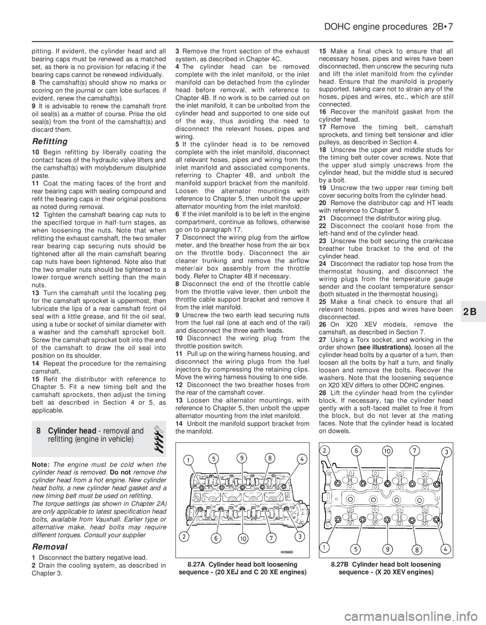
27Using a Torx socket, and working in the
order shown (see illustrations), loosen all the
cylinder head bolts by a quarter of a turn, then
loosen all the bolts by half a turn, and finally
loosen and remove the bolts. Recover the
washers. Note that the loosening sequence
on X20 XEV differs to other DOHC engines.
28Lift the cylinder head from the cylinder
block. If necessary, tap the cylinder head
gently with a soft-faced mallet to free it from
the block, but do not lever at the mating
faces. Note that the cylinder head is located
on dowels.
DOHC engine procedures 2B•7
8.27B Cylinder head bolt loosening
sequence - (X 20 XEV engines)8.27A Cylinder head bolt loosening
sequence - (20 XEJ and C 20 XE engines)
2B
Page 204 of 525
Oil pick-up pipe bracket to cylinder block . . . . . . . . . . . . . . . . . . . . . . .64
Oil pick-up pipe to oil pump . . . . . . . . . . . . . . . . . . . . . . . . . . . . . . . . . .86
Oil pipes to radiator . . . . . . . . . . . . . . . . . . . . . . . . . . . . . . . . . . . . . . . .2216
Oil pressure switch to oil pump:
1.4 and 1.6 litre, (except C16 NZ2) . . . . . . . . . . . . . . . . . . . . . . . . . .3022
C16 NZ2, 1.8 and 2.0 litre . . . . . . . . . . . . . . . . . . . . . . . . . . . . . . . . . .4030
Oil pressure relief valve to oil pump . . . . . . . . . . . . . . . . . . . . . . . . . . . .3022
Oil pump cover to oil pump . . . . . . . . . . . . . . . . . . . . . . . . . . . . . . . . . .64
Oil pump to cylinder block . . . . . . . . . . . . . . . . . . . . . . . . . . . . . . . . . . .64
Oxygen sensor to exhaust manifold . . . . . . . . . . . . . . . . . . . . . . . . . . . .3022
Power steering pump bracket to support:
C16 NZ2, 1.8 and 2.0 litre . . . . . . . . . . . . . . . . . . . . . . . . . . . . . . . . . .1813
Power steering pump to support . . . . . . . . . . . . . . . . . . . . . . . . . . . . . .2518
Right engine mounting to subframe . . . . . . . . . . . . . . . . . . . . . . . . . . . .6548
Shackle to alternator . . . . . . . . . . . . . . . . . . . . . . . . . . . . . . . . . . . . . . . .2518
Spark plugs . . . . . . . . . . . . . . . . . . . . . . . . . . . . . . . . . . . . . . . . . . . . . . .2518
Starter to cylinder block (M10) . . . . . . . . . . . . . . . . . . . . . . . . . . . . . . . .4533
Starter to cylinder block (M12) . . . . . . . . . . . . . . . . . . . . . . . . . . . . . . . .6044
Sump:
1.4 and 1.6 litre, (except C16 NZ2) . . . . . . . . . . . . . . . . . . . . . . . . . . .86
C16 NZ2, 1.8 and 2.0 litre . . . . . . . . . . . . . . . . . . . . . . . . . . . . . . . . . .1511
Sump drain plug . . . . . . . . . . . . . . . . . . . . . . . . . . . . . . . . . . . . . . . . . . .5541
Support to cylinder block . . . . . . . . . . . . . . . . . . . . . . . . . . . . . . . . . . . .3526
Temperature sender to cylinder head . . . . . . . . . . . . . . . . . . . . . . . . . . .2015
Thermostat housing:
1.4 and 1.6 litre, (except C16 NZ2) . . . . . . . . . . . . . . . . . . . . . . . . . . .107
C16 NZ2, 1.8 and 2.0 litre . . . . . . . . . . . . . . . . . . . . . . . . . . . . . . . . . .1511
Timing belt tensioner to oil pump:
1.4 and 1.6 litre, (except C16 NZ2) . . . . . . . . . . . . . . . . . . . . . . . . . . .5541
Timing belt cover to oil pump/camshaft housing:
1.4 and 1.6 litre, (except C16 NZ2) . . . . . . . . . . . . . . . . . . . . . . . . . . .129
C16 NZ2, 1.8 and 2.0 litre . . . . . . . . . . . . . . . . . . . . . . . . . . . . . . . . . .64
Timing belt drive gear to crankshaft:
C16 NZ2, 1.8 and 2.0 litre:
Stage 1 . . . . . . . . . . . . . . . . . . . . . . . . . . . . . . . . . . . . . . . . . . . . . .13096
Stage 2 . . . . . . . . . . . . . . . . . . . . . . . . . . . . . . . . . . . . . . . . . . . . . .Angle tighten by between 40º to 50º
Transmission to engine (M10) . . . . . . . . . . . . . . . . . . . . . . . . . . . . . . . . .4533
Transmission to engine (M12) . . . . . . . . . . . . . . . . . . . . . . . . . . . . . . . . .6044
1General description
General
The engine is of four-cylinder, in-line single
or double overhead camshaft type (depending
on model), mounted transversely at the front
of the vehicle.
The crankshaft runs in five shell-type
bearings, and the centre bearing incorporates
a thrust bearing shell to control crankshaft
endfloat.
The connecting rods are attached to the
crankshaft by horizontally split shell-type
big-end bearings. On single overhead
camshaft (SOHC) models, the pistons are
attached to the connecting rods by gudgeon
pins, which are an interference fit in the
connecting rod small-end bore. The
aluminium alloy pistons are fitted with three
piston rings: two compression rings and an oil
control ring.
The camshaft on SOHC engines is driven
from the crankshaft by a toothed composite
rubber belt. Each cylinder has two valves (oneinlet and one exhaust), operated through
rocker arms that are supported at their pivot
ends by hydraulic self-adjusting valve lifters
(tappets).
The inlet and exhaust valves are each
closed by a single valve spring, and operate in
guides pressed into the cylinder head.
A gear-type oil pump is located in a housing
attached to the front of the cylinder block, and
is driven directly from the crankshaft. A
full-flow type oil filter is fitted.
The distributor is driven directly from the
end of the camshaft. On carburettor models,
the mechanical fuel pump is operated from
the front end of the camshaft. The coolant
pump is located at the front of the cylinder
block, and is driven by the timing belt.
Chapter 2A describes the SOHC engine
repair procedures. Many repairs and specifi-
cations to the DOHC engine are similar to the
2.0 litre SOHC. However where they differ,
details can be found in Chapter 2B.
Engine identification codes -
general
Before ordering spare parts, or carrying out
any repair or overhaul operations on the
engine, it is essential to identify the exactengine type being worked on. Later engines,
although outwardly similar in appearance,
often have significant differences in repair
procedures, even though they may be of the
same displacement and model year.
The following sub-Sections in this Chapter
are mainly specific to engine type, as will be
noted from the sub-Section headings. Check
the engine identification code first, which is
located on a horizontal surface on the exhaust
manifold side of the cylinder block, at the
distributor end. On later engines, the code is
on the cylinder block-to-transmission flange,
next to the engine oil dipstick.
2Crankcase ventilation
system - description and
maintenance
2
Description
1A crankcase ventilation system is fitted to
all models, but the systems differ in detail
depending on the model concerned.
2Oil fumes and blow-by gases (combustion
gases that have passed by the piston rings)
are drawn from the crankcase into the area of
SOHC engine procedures 2A•7
2A
Page 216 of 525
Inspection
7With the camshaft removed, examine the
bearings in the camshaft housing for signs of
obvious wear or pitting. If evident, a new
camshaft housing will probably be required.
8The camshaft itself should show no marks
or scoring on the journal or cam lobe
surfaces. If evident, renew the camshaft. Note
that if the camshaft is renewed, all the rocker
arms should also be renewed.
9Check the camshaft thrustplate for signs of
wear or grooves, and renew if evident.
10It is advisable to renew the camshaft front
oil seal as a matter of course if the camshaft
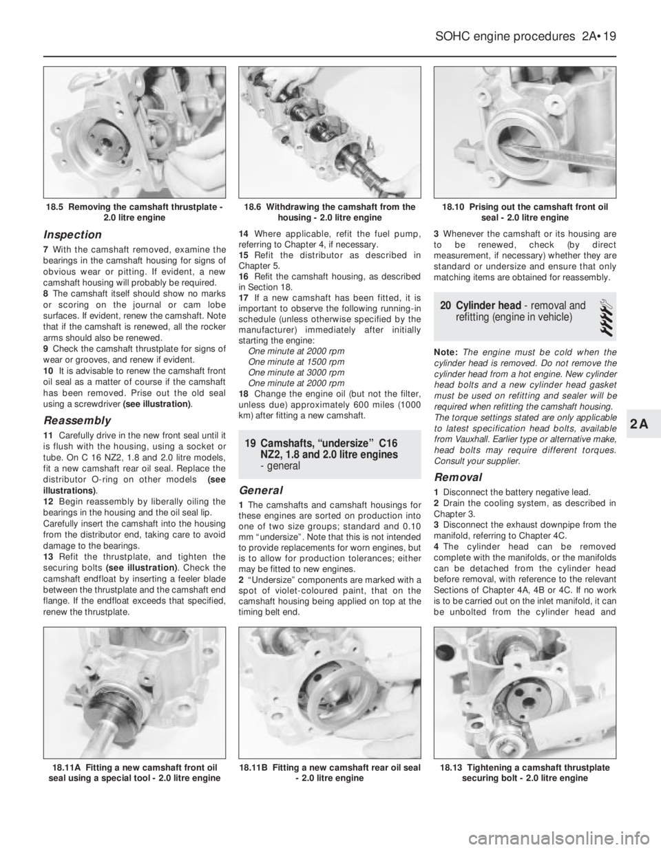
has been removed. Prise out the old seal
using a screwdriver (see illustration).
Reassembly
11Carefully drive in the new front seal until it
is flush with the housing, using a socket or
tube. On C 16 NZ2, 1.8 and 2.0 litre models,
fit a new camshaft rear oil seal. Replace the
distributor O-ring on other models (see
illustrations).
12Begin reassembly by liberally oiling the
bearings in the housing and the oil seal lip.
Carefully insert the camshaft into the housing
from the distributor end, taking care to avoid
damage to the bearings.
13Refit the thrustplate, and tighten the
securing bolts (see illustration). Check the
camshaft endfloat by inserting a feeler blade
between the thrustplate and the camshaft end
flange. If the endfloat exceeds that specified,
renew the thrustplate.14Where applicable, refit the fuel pump,
referring to Chapter 4, if necessary.
15Refit the distributor as described in
Chapter 5.
16Refit the camshaft housing, as described
in Section 18.
17If a new camshaft has been fitted, it is
important to observe the following running-in
schedule (unless otherwise specified by the
manufacturer) immediately after initially
starting the engine:
One minute at 2000 rpm
One minute at 1500 rpm
One minute at 3000 rpm
One minute at 2000 rpm
18Change the engine oil (but not the filter,
unless due) approximately 600 miles (1000
km) after fitting a new camshaft.19Camshafts, “undersize” C16
NZ2, 1.8 and 2.0 litre engines
- general
General
1The camshafts and camshaft housings for
these engines are sorted on production into
one of two size groups; standard and 0.10
mm “undersize”. Note that this is not intended
to provide replacements for worn engines, but
is to allow for production tolerances; either
may be fitted to new engines.
2“Undersize” components are marked with a
spot of violet-coloured paint, that on the
camshaft housing being applied on top at the
timing belt end.3Whenever the camshaft or its housing are
to be renewed, check (by direct
measurement, if necessary) whether they are
standard or undersize and ensure that only
matching items are obtained for reassembly.
20Cylinder head - removal and
refitting (engine in vehicle)
4
Note: The engine must be cold when the
cylinder head is removed. Do not remove the
cylinder head from a hot engine. New cylinder
head bolts and a new cylinder head gasket
must be used on refitting and sealer will be
required when refitting the camshaft housing.
The torque settings stated are only applicable
to latest specification head bolts, available
from Vauxhall. Earlier type or alternative make,
head bolts may require different torques.
Consult your supplier.
Removal
1Disconnect the battery negative lead.
2Drain the cooling system, as described in
Chapter 3.
3Disconnect the exhaust downpipe from the
manifold, referring to Chapter 4C.
4The cylinder head can be removed
complete with the manifolds, or the manifolds
can be detached from the cylinder head
before removal, with reference to the relevant
Sections of Chapter 4A, 4B or 4C. If no work
is to be carried out on the inlet manifold, it can
be unbolted from the cylinder head and
SOHC engine procedures 2A•19
18.10 Prising out the camshaft front oil
seal - 2.0 litre engine
18.13 Tightening a camshaft thrustplate
securing bolt - 2.0 litre engine18.11B Fitting a new camshaft rear oil seal
- 2.0 litre engine18.11A Fitting a new camshaft front oil
seal using a special tool - 2.0 litre engine
18.6 Withdrawing the camshaft from the
housing - 2.0 litre engine18.5 Removing the camshaft thrustplate -
2.0 litre engine
2A