1988 OPEL CALIBRA ECO mode
[x] Cancel search: ECO modePage 219 of 525
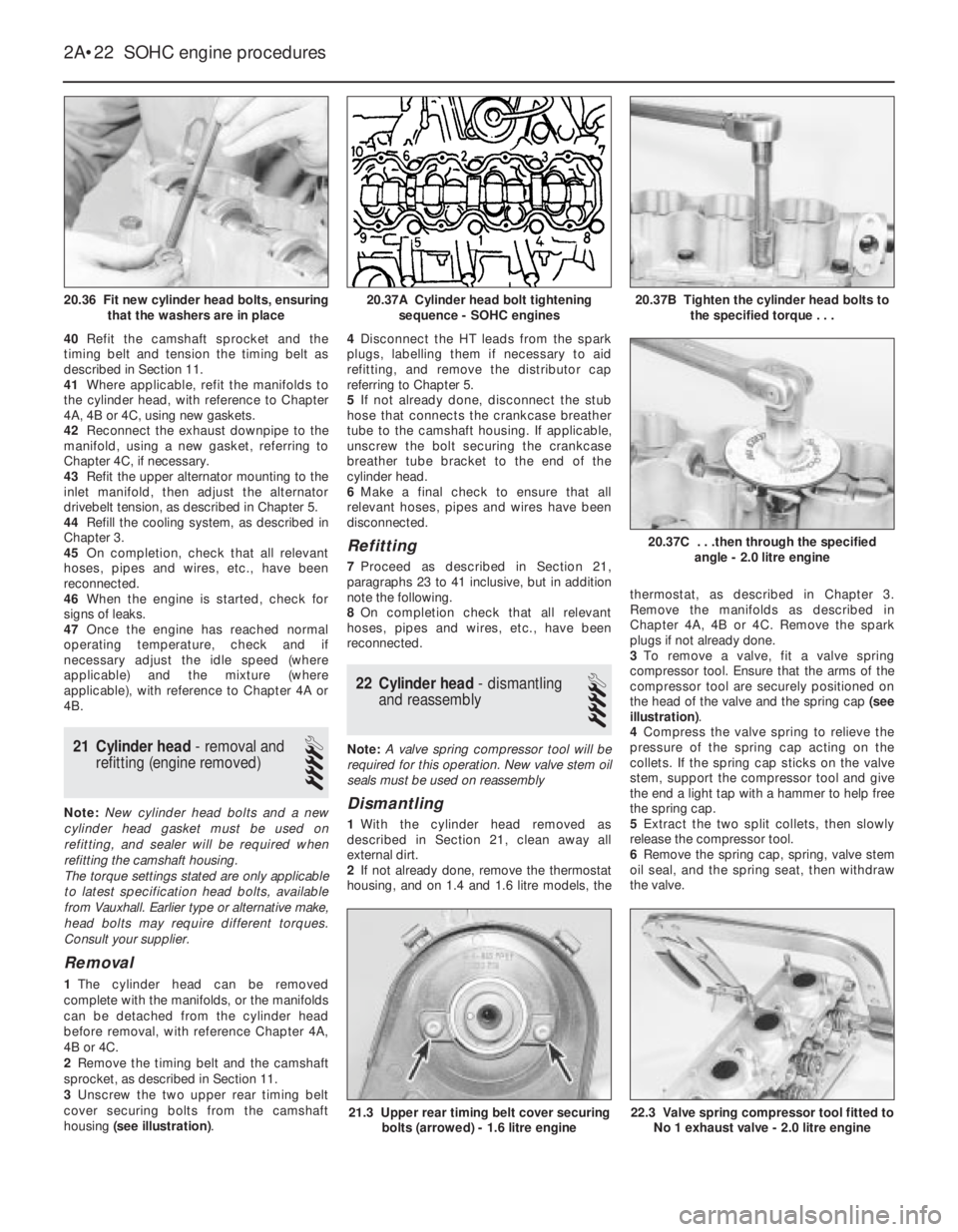
40Refit the camshaft sprocket and the
timing belt and tension the timing belt as
described in Section 11.
41Where applicable, refit the manifolds to
the cylinder head, with reference to Chapter
4A, 4B or 4C, using new gaskets.
42Reconnect the exhaust downpipe to the
manifold, using a new gasket, referring to
Chapter 4C, if necessary.
43Refit the upper alternator mounting to the
inlet manifold, then adjust the alternator
drivebelt tension, as described in Chapter 5.
44Refill the cooling system, as described in
Chapter 3.
45On completion, check that all relevant
hoses, pipes and wires, etc., have been
reconnected.
46When the engine is started, check for
signs of leaks.
47Once the engine has reached normal
operating temperature, check and if
necessary adjust the idle speed (where
applicable) and the mixture (where
applicable), with reference to Chapter 4A or
4B.
21Cylinder head - removal and
refitting (engine removed)
4
Note: New cylinder head bolts and a new
cylinder head gasket must be used on
refitting, and sealer will be required when
refitting the camshaft housing.
The torque settings stated are only applicable
to latest specification head bolts, available
from Vauxhall. Earlier type or alternative make,
head bolts may require different torques.
Consult your supplier.
Removal
1The cylinder head can be removed
complete with the manifolds, or the manifolds
can be detached from the cylinder head
before removal, with reference Chapter 4A,
4B or 4C.
2Remove the timing belt and the camshaft
sprocket, as described in Section 11.
3Unscrew the two upper rear timing belt
cover securing bolts from the camshaft
housing (see illustration).4Disconnect the HT leads from the spark
plugs, labelling them if necessary to aid
refitting, and remove the distributor cap
referring to Chapter 5.
5If not already done, disconnect the stub
hose that connects the crankcase breather
tube to the camshaft housing. If applicable,
unscrew the bolt securing the crankcase
breather tube bracket to the end of the
cylinder head.
6Make a final check to ensure that all
relevant hoses, pipes and wires have been
disconnected.
Refitting
7Proceed as described in Section 21,
paragraphs 23 to 41 inclusive, but in addition
note the following.
8On completion check that all relevant
hoses, pipes and wires, etc., have been
reconnected.
22Cylinder head -dismantling
and reassembly
4
Note: A valve spring compressor tool will be
required for this operation. New valve stem oil
seals must be used on reassembly
Dismantling
1With the cylinder head removed as
described in Section 21, clean away all
external dirt.
2If not already done, remove the thermostat
housing, and on 1.4 and 1.6 litre models, thethermostat, as described in Chapter 3.
Remove the manifolds as described in
Chapter 4A, 4B or 4C. Remove the spark
plugs if not already done.
3To remove a valve, fit a valve spring
compressor tool. Ensure that the arms of the
compressor tool are securely positioned on
the head of the valve and the spring cap (see
illustration).
4Compress the valve spring to relieve the
pressure of the spring cap acting on the
collets. If the spring cap sticks on the valve
stem, support the compressor tool and give
the end a light tap with a hammer to help free
the spring cap.
5Extract the two split collets, then slowly
release the compressor tool.
6Remove the spring cap, spring, valve stem
oil seal, and the spring seat, then withdraw
the valve.
2A•22SOHC engine procedures
20.36 Fit new cylinder head bolts, ensuring
that the washers are in place20.37B Tighten the cylinder head bolts to
the specified torque . . .
22.3 Valve spring compressor tool fitted to
No 1 exhaust valve - 2.0 litre engine21.3 Upper rear timing belt cover securing
bolts (arrowed) - 1.6 litre engine
20.37C . . .then through the specified
angle - 2.0 litre engine
20.37A Cylinder head bolt tightening
sequence - SOHC engines
Page 224 of 525
28Crankshaft rear oil seal -
renewal
4
Renewal
1With the engine removed from the vehicle,
remove the flywheel, or flexplate (as
applicable) as described in Sections 25 and
26.
2Punch or drill a small hole in the centre of
the now-exposed oil seal. Screw in a
self-tapping screw, and pull on the screw with
pliers to extract the seal. Several attempts
may be necessary. Be careful not to damage
the sealing face of the crankshaft.
3Clean the oil seal seat with a wooden or
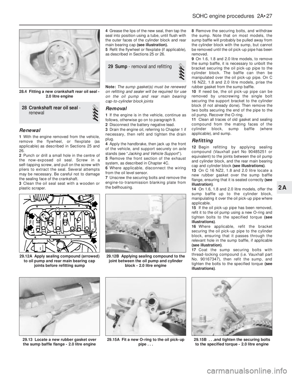
plastic scraper.4Grease the lips of the new seal, then tap the
seal into position using a tube, until flush with
the outer faces of the cylinder block and rear
main bearing cap (see illustration).
5Refit the flywheel or flexplate (if applicable),
as described in Sections 25 or 26.
29Sump - removal and refitting
4
Note: The sump gasket(s) must be renewed
on refitting and sealer will be required for use
on the oil pump and rear main bearing
cap-to-cylinder block joints
Removal
1If the engine is in the vehicle, continue as
follows, otherwise go on to paragraph 9.
2Disconnect the battery negative lead.
3Drain the engine oil, referring to Chapter 1 if
necessary, then refit and tighten the drain
plug.
4Apply the handbrake, then jack up the front
of the vehicle, and support securely on axle
stands (see “Jacking and Vehicle Support”).
5Remove the front section of the exhaust
system, as described in Chapter 4C.
6Where applicable, disconnect the wiring
from the oil level sensor.
7Unscrew the securing bolts and remove the
engine-to-transmission blanking plate from
the bellhousing.8Remove the securing bolts, and withdraw
the sump. Note that on most models, the
sump baffle will probably be pulled away from
the cylinder block with the sump, but cannot
be removed until the oil pick-up pipe has been
removed.
9On 1.6, 1.8 and 2.0 litre models, to remove
the sump baffle, it is necessary to unbolt the
bracket securing the oil pick-up pipe to the
cylinder block. The baffle can then be
manipulated over the oil pick-up pipe. On C
16 NZ2, 1.8 and 2.0 litre models, prise the
rubber gasket from the sump baffle.
10If need be, the oil pick-up pipe can be
removed by unscrewing the single bolt
securing the support bracket to the cylinder
block (if not already done). Then remove the
two bolts securing the end of the pipe to the
oil pump. Recover the O-ring.
11Clean all traces of old gasket and sealing
compound from the mating faces of the
cylinder block, sump baffle (where
applicable), and sump.
Refitting
12Begin refitting by applying sealing
compound (Vauxhall part No 90485251 or
equivalent) to the joints between the oil pump
and cylinder block, and the rear main bearing
cap and cylinder block (see illustrations).
13On C 16 NZ2, 1.8 and 2.0 litre locate a
new rubber gasket over the sump baffle
flange, ensuring that it is seated correctly (see
illustration).
14On 1.6, 1.8 and 2.0 litre models, offer the
sump baffle up to the cylinder block,
manipulating it over the oil pick-up pipe where
applicable.
15If the oil pick-up pipe has been removed,
refit it to the oil pump using a new O-ring and
tighten bolts to the specified torque (see
illustrations).
16Where applicable, refit the bracket
securing the oil pick-up pipe to the cylinder
block, ensuring that it passes through the
relevant hole in the sump baffle, if applicable
(see illustration).
17Coat the sump securing bolts with
thread-locking compound (i.e. Vauxhall part
No. 90167347), then refit the sump, and
tighten the bolts to the specified torque (see
illustrations).
SOHC engine procedures 2A•27
29.12B Applying sealing compound to the
joint between the oil pump and cylinder
block - 2.0 litre engine
29.15B . . .and tighten the securing bolts
to the specified torque - 2.0 litre engine29.15A Fit a new O-ring to the oil pick-up
pipe . . .29.13 Locate a new rubber gasket over
the sump baffle flange - 2.0 litre engine
29.12A Apply sealing compound (arrowed)
to oil pump and rear main bearing cap
joints before refitting sump
28.4 Fitting a new crankshaft rear oil seal -
2.0 litre engine
2A
Page 233 of 525
1General description
Engine cooling is achieved by a
conventional pump-assisted system, in which
the coolant is pressurised. The system
consists of a radiator, a coolant pump driven
by the engine timing belt, an electric cooling
fan, a thermostat, an expansion tank, and
connecting hoses. Hoses also carry coolant to
and from the heater matrix, which provides
heat for the ventilation and heating system.
The system works in the following way.
Cold coolant from one side of the radiator,
which is mounted at the front of the engine
compartment, passes to the coolant pump,
which forces the coolant through the coolant
passages in the cylinder block and cylinder
head. The coolant absorbs heat from the
engine, and then returns to the radiator
through the heater matrix. As the coolant
flows across the radiator it is cooled, and the
cycle is repeated.
Air flows through the radiator, to cool the
coolant as a result of the vehicle’s forward
motion. However, if the coolant temperature
exceeds a given figure, a
temperature-sensitive switch in the radiator
switches on the electric fan, to increase the
airflow through the radiator. The fan only
operates when necessary, with a consequent
reduction in noise and energy consumption.
To reduce the time taken for the engine to
warm up when starting from cold, the
thermostat, located in the cylinder head
outlet, prevents coolant flowing to the radiator
until the temperature has risen sufficiently.
Instead, the outflow from the cylinder head
bypasses the radiator, and is redirected
around the engine. When the temperature
reaches a given figure, the thermostat opens,
to allow coolant to flow to the radiator. The
thermostat is operated by the expansion of a
temperature sensitive wax capsule.
An expansion tank is incorporated in the
system, to allow for coolant expansion. The
system is topped up through a filler cap on
the expansion tank.
Note that later models may be fitted with
self-tensioning spring clamps to secure the
cooling system (including heater) hoses.
These clamps can be released by squeezing
together their free ends using a large pair of
self-grip pliers or similar so that the clamp can
be moved up the hose, clear of the union.
Check that the clamp is securely seated, and
check for leaks on reassembly.
2Cooling system -draining
2
1With the vehicle parked on level ground,
remove the expansion tank filler cap. If the
engine is warm, cover the filler cap with a
thick cloth, and unscrew the cap slowly, to
gradually relieve the system pressure. Take
care to avoid scalding by steam or coolant
escaping from the pressurised system.
2On DOHC models, remove the engine
undershield, with reference to Chapter 11.
3Position a container beneath the radiator
bottom hose connection, then slacken the
hose clip and ease the hose from the radiator
stub. If the hose joint has not been disturbed
for some time, it will be necessary to
manipulate the hose to break the joint. Allow
the coolant to drain into the container.
4As no cylinder block drain plug is fitted, and
the radiator bottom hose may be situated
halfway up the radiator, the system cannot be
drained completely. Care should therefore be
taken when refilling the system to maintain
antifreeze strength.
5If the coolant has been drained for a reason
other than renewal, then provided it is clean
and less than two years old, it can be re-used.
6If the coolant has been drained for renewal,
and is badly contaminated, the coolant
system should be flushed as described in
Section 4. As the system cannot be drained
completely, it is advisable to flush the system
whenever the coolant is renewed, to minimise
the impurities remaining in the system.
3Cooling system -flushing
2
1If coolant renewal has been neglected, or if
the antifreeze mixture has become diluted,
then in time the cooling system will gradually
lose efficiency, as the coolant passages
become restricted due to rust, scale deposits
and other sediment. To restore coolant
system efficiency, it is necessary to flush the
system clean.
2The radiator should be flushed
independently of the engine, to avoid
unnecessary contamination.
3To flush the radiator, disconnect the top
hose at the radiator, then insert a garden hose
into the radiator top inlet. Direct a flow of
clean water through the radiator, and continue
flushing until clean water emerges from the
radiator bottom outlet (the bottom hose
should have been disconnected to drain the
system). If after a reasonable period, the water
still does not run clear, the radiator can be
flushed with a good proprietary cleaning
agent. It is important that the manufacturer’s
instructions are followed carefully. If the
contamination is particularly bad, insert the
hose in the radiator bottom outlet, and flush
the radiator in reverse.
4To flush the engine, continue as follows.
1.4 and 1.6 litre models (except
C16 NZ2)
5Remove the thermostat as described in
Section 9, then temporarily refit the
thermostat cover.
6With the radiator top and bottom hoses
disconnected from the radiator, insert a
garden hose into the radiator bottom hose.
Direct a flow of clean water through the
engine, and continue flushing until clean water
emerges from the radiator top hose.
7On completion of flushing, refit the
thermostat, and reconnect the hoses.
C16 NZ2, 1.8 and 2.0 litre
models
8Remove the thermostat and cover
assembly, as described in Section 9.
9With the radiator bottom hose
disconnected from the radiator, insert a
garden hose into the radiator bottom hose.
Direct a flow of clean water through the
engine, and continue flushing until clean water
emerges from the thermostat housing. It is
advisable to place a sheet of plastic under the
thermostat housing to deflect water away
from the engine and surrounding components
during the flushing process.
10On completion of flushing, refit the
thermostat and cover assembly, reconnect
the hoses and remove the sheet of plastic.
4Cooling system -filling
2
1Before attempting to fill the cooling system,
make sure that all hoses and clips are in good
condition, and that the clips are tight. Note
that an antifreeze mixture must be used all
year round, to prevent corrosion of the alloy
engine components -refer to Section 5.
2On 1.4 and 1.6 litre models (except C16
NZ2), disconnect the wire and unscrew the
coolant temperature sender from the inlet
manifold.
3Remove the expansion tank cap, and fill the
system by slowly pouring the coolant into the
expansion tank to prevent air locks from
forming.
4If the coolant is being renewed, begin by
pouring in a couple of pints of water, followed
by the correct quantity of antifreeze (see
Section 5), then top-up with more water.
5On 1.4 and 1.6 litre models (except C16
NZ2), refit the coolant temperature sender
when coolant free of air bubbles emerges
from the orifice in the inlet manifold.
6Top-up the coolant level to the “COLD” (or
“KALT”) mark on the expansion tank, then refit
the expansion tank cap.
7Start the engine and run it until it reaches
normal operating temperature, then stop the
engine and allow it to cool.
8Check for leaks, particularly around
disturbed components. Check the coolant
3•2Cooling, heating and ventilation systems
When renewing any hoses,
use a little soapy water as a
lubricant, or soften the hose
in hot water. Do not use oil or
grease, as this may attack the rubber.
Page 235 of 525
8Radiator -inspection and
cleaning
2
1If the radiator has been removed due to
suspected blockage, reverse-flush it as
described in Section 3.
2Clean dirt and debris from the radiator fins,
using an air jet or a soft brush. Take care, as
the fins are easily damaged and are sharp.
3If necessary, a radiator specialist can
perform a “flow test” on the radiator, to
establish whether an internal blockage exists.
4A leaking radiator must be referred to a
specialist for permanent repair. Do not
attempt to weld or solder a leaking radiator,
as damage to the plastic components may
result.
5In an emergency, minor leaks from the
radiator can be cured by using a radiator
sealant.
9Thermostat - removal and
refitting
3
Note: A new O-ring should be used when
refitting the thermostat
1.4 and 1.6 litre models (except
C16 NZ2)
Removal
1Partially drain the cooling system, as
described in Section 2.
2Remove the timing belt and the camshaft
sprocket, as described in Chapters 2A or 2B,
(as applicable).
3Unscrew and remove the two upper bolts
securing the rear timing belt cover to the
cylinder head, and the lower right-hand bolt
securing the cover to the cylinder block.
4Disconnect the coolant hose from the
thermostat housing.
5Pull the rear timing belt cover forwards,
away from the cylinder head, for access to the
two thermostat housing securing bolts.
6Unscrew and remove the two thermostat
housing securing bolts, and lift off the
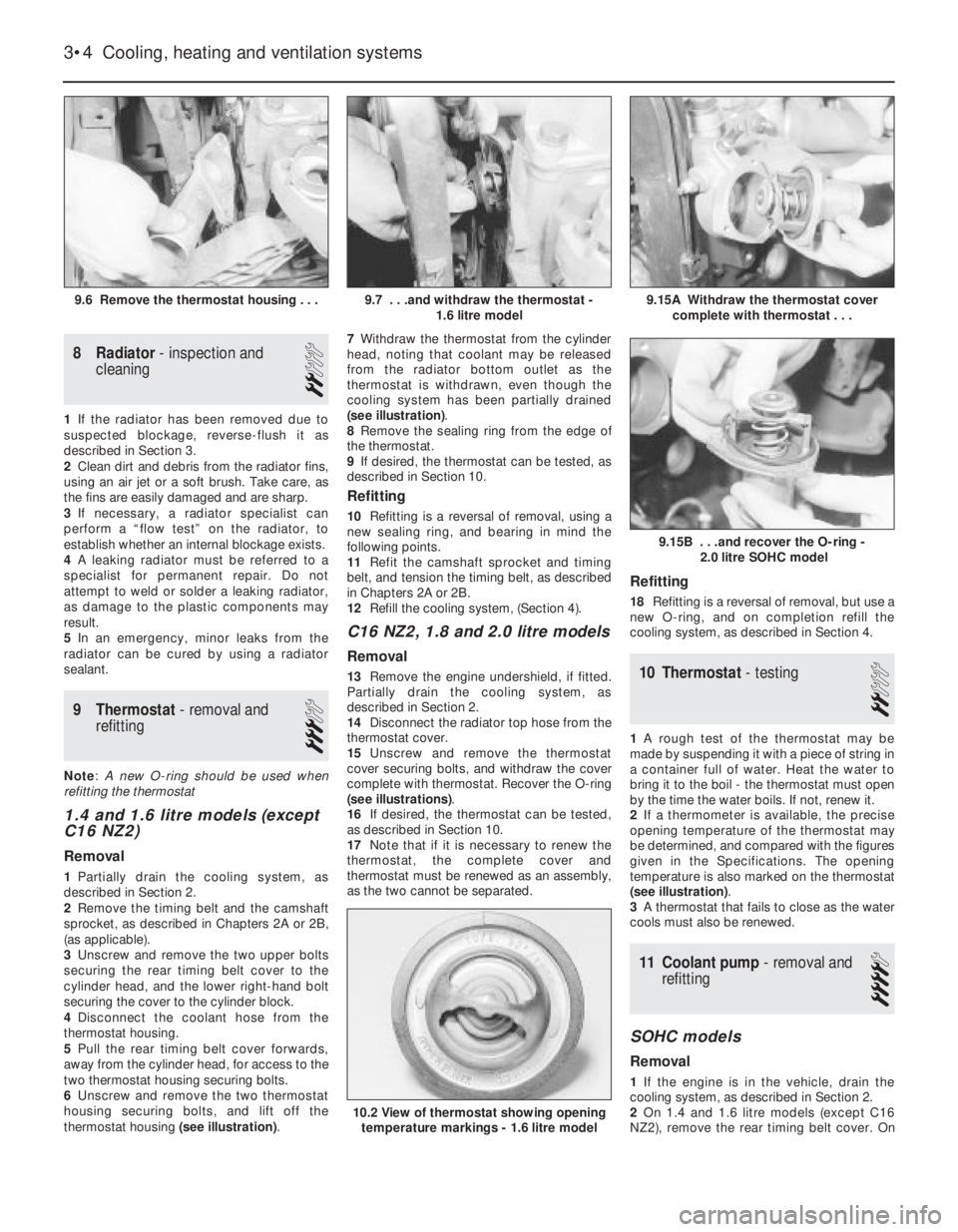
thermostat housing (see illustration).7Withdraw the thermostat from the cylinder
head, noting that coolant may be released
from the radiator bottom outlet as the
thermostat is withdrawn, even though the
cooling system has been partially drained
(see illustration).
8Remove the sealing ring from the edge of
the thermostat.
9If desired, the thermostat can be tested, as
described in Section 10.
Refitting
10Refitting is a reversal of removal, using a
new sealing ring, and bearing in mind the
following points.
11Refit the camshaft sprocket and timing
belt, and tension the timing belt, as described
in Chapters 2A or 2B.
12Refill the cooling system, (Section 4).
C16 NZ2, 1.8 and 2.0 litre models
Removal
13Remove the engine undershield, if fitted.
Partially drain the cooling system, as
described in Section 2.
14Disconnect the radiator top hose from the
thermostat cover.
15Unscrew and remove the thermostat
cover securing bolts, and withdraw the cover
complete with thermostat. Recover the O-ring
(see illustrations).
16If desired, the thermostat can be tested,
as described in Section 10.
17Note that if it is necessary to renew the
thermostat, the complete cover and
thermostat must be renewed as an assembly,
as the two cannot be separated.
Refitting
18Refitting is a reversal of removal, but use a
new O-ring, and on completion refill the
cooling system, as described in Section 4.
10Thermostat -testing
2
1A rough test of the thermostat may be
made by suspending it with a piece of string in
a container full of water. Heat the water to
bring it to the boil -the thermostat must open
by the time the water boils. If not, renew it.
2If a thermometer is available, the precise
opening temperature of the thermostat may
be determined, and compared with the figures
given in the Specifications. The opening
temperature is also marked on the thermostat
(see illustration).
3A thermostat that fails to close as the water
cools must also be renewed.
11Coolant pump -removal and
refitting
4
SOHC models
Removal
1If the engine is in the vehicle, drain the
cooling system, as described in Section 2.
2On 1.4 and 1.6 litre models (except C16
NZ2), remove the rear timing belt cover. On
3•4Cooling, heating and ventilation systems
9.6 Remove the thermostat housing . . .9.15A Withdraw the thermostat cover
complete with thermostat . . .
10.2 View of thermostat showing opening
temperature markings - 1.6 litre model
9.15B . . .and recover the O-ring -
2.0 litre SOHC model
9.7 . . .and withdraw the thermostat -
1.6 litre model
Page 236 of 525
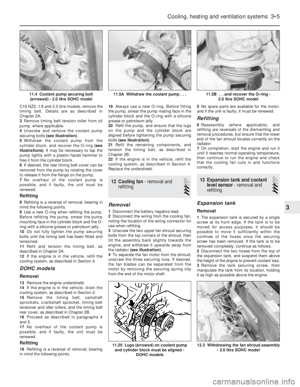
C16 NZ2, 1.8 and 2.0 litre models, remove the
timing belt. Details are as described in
Chapter 2A.
3Remove timing belt tension roller from oil
pump, where applicable.
4Unscrew and remove the coolant pump
securing bolts (see illustration).
5Withdraw the coolant pump from the
cylinder block, and recover the O-ring (see
illustrations). It may be necessary to tap the
pump lightly with a plastic-faced hammer to
free it from the cylinder block.
6If desired, the rear timing belt cover can be
removed from the pump by rotating the cover
to release it from the flange on the pump.
7No overhaul of the coolant pump is
possible, and if faulty, the unit must be
renewed.
Refitting
8Refitting is a reversal of removal, bearing in
mind the following points.
9Use a new O-ring when refitting the pump.
Before refitting the pump, smear the pump
mounting face in the cylinder block and the O-
ring with a silicone grease or petroleum jelly.
10Do not fully tighten the pump securing
bolts until the timing belt has been fitted and
tensioned.
11Refit and tension the timing belt, as
described in Chapter 2A.
12If the engine is in the vehicle, refill the
cooling system, as described in Section 4.
DOHC models
Removal
13Remove the engine undershield.
14If the engine is in the vehicle, drain the
cooling system, as described in Section 2.
15Remove the timing belt, camshaft
sprockets, crankshaft sprocket, timing belt
tensioner and idler rollers, and the timing belt
rear cover, as described in Chapter 2B.
16Proceed as described in paragraphs 4
and 5.
17No overhaul of the coolant pump is
possible, and if faulty, the unit must be
renewed.
Refitting
18Refitting is a reversal of removal, bearing
in mind the following points.19Always use a new O-ring. Before fitting
the pump, smear the pump mating face in the
cylinder block and the O-ring with a silicone
grease or petroleum jelly.
20Refit the pump, and ensure that the lugs
on the pump and the cylinder block are
aligned before tightening the pump securing
bolts (see illustration).
21Refit the remaining components, and
tension the timing belt, as described in
Chapter 2B.
22If the engine is in the vehicle, refill the
cooling system, as described in Section 4.
Replace the undershield.
12Cooling fan - removal and
refitting
3
Removal
1Disconnect the battery negative lead.
2Disconnect the wiring from the cooling fan,
noting the location of the wiring connector for
use when refitting.
3Unscrew the two upper fan shroud securing
bolts from the top corners of the shroud, then
tilt the assembly back slightly towards the
engine, and withdraw it upwards away from
the radiator (see illustration).
4To separate the fan motor from the shroud,
unscrew the three securing nuts. If desired,
the fan blades can be separated from the
motor by removing the securing spring clip
from the end of the motor shaft.5No spare parts are available for the motor,
and if the unit is faulty, it must be renewed.
Refitting
6Reassembly (where applicable), and
refitting are reversals of the dismantling and
removal procedures, but ensure that the lower
end of the fan shroud locates correctly on the
radiator.
7On completion, start the engine and run it
until it reaches normal operating temperature,
then continue to run the engine and check
that the cooling fan cuts in and functions
correctly.
13Expansion tank and coolant
level sensor -removal and
refitting
3
Expansion tank
Removal
1The expansion tank is secured by a single
screw at its front edge. If the tank is to be
moved for access purposes, it should be
possible to move it sufficiently within the
confines of the hoses once the securing
screw has been removed. If the tank is to be
removed completely, continue as follows.
2Disconnect the two hoses from the top of
the expansion tank, and suspend them above
the height of the engine to prevent coolant loss.
3Remove the tank securing screw, then
manipulate the tank from its location, holding
it as high as possible above the engine.
Cooling, heating and ventilation systems 3•5
11.5B . . .and recover the O-ring -
2.0 litre SOHC model
12.3 Withdrawing the fan shroud assembly
- 2.0 litre SOHC model11.20 Lugs (arrowed) on coolant pump
and cylinder block must be aligned -
DOHC models
11.5A Withdraw the coolant pump . . .11.4 Coolant pump securing bolt
(arrowed) - 2.0 litre SOHC model
3
Page 237 of 525
4Position a container beneath the tank, then
disconnect the bottom hose and allow the
contents of the tank to drain into the
container. Suspend the bottom hose as high
as possible above the engine to prevent
coolant loss.
Refitting
5Refitting is a reversal of removal, but on
completion check and if necessary top-up the
coolant level, as described in Section 4. The
coolant drained from the expansion tank
during removal can be re-used, provided it
has not been contaminated.
Coolant level sensor
6The coolant level sensor, where fitted, is an
integral part of the expansion tank cap. If the
level sensor is faulty, the complete cap
assembly must be renewed.
14Temperature gauge sender -
removal and refitting
2
Removal
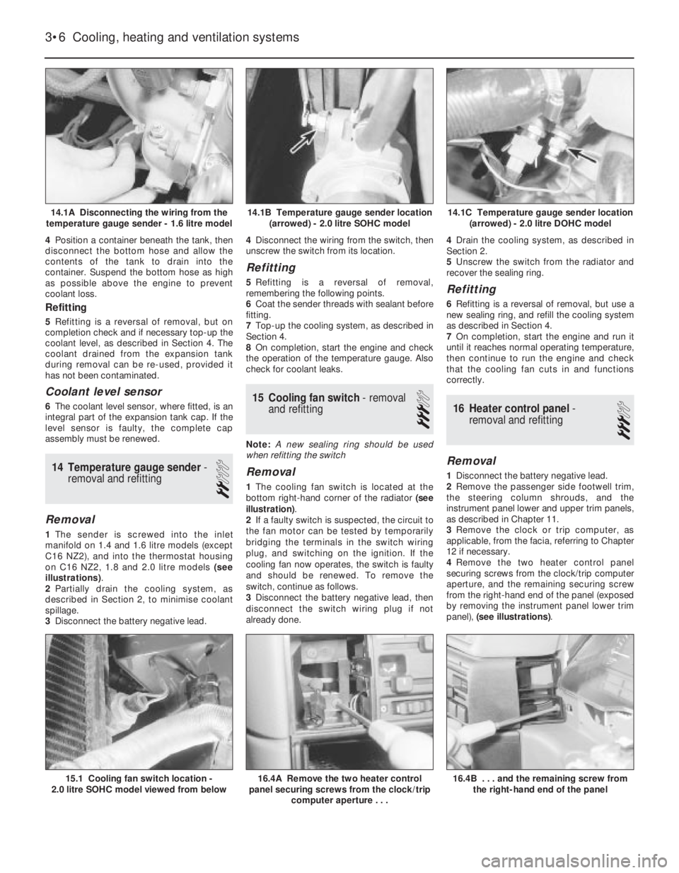
1The sender is screwed into the inlet
manifold on 1.4 and 1.6 litre models (except
C16 NZ2), and into the thermostat housing
on C16 NZ2, 1.8 and 2.0 litre models (see
illustrations).
2Partially drain the cooling system, as
described in Section 2, to minimise coolant
spillage.
3Disconnect the battery negative lead.4Disconnect the wiring from the switch, then
unscrew the switch from its location.
Refitting
5Refitting is a reversal of removal,
remembering the following points.
6Coat the sender threads with sealant before
fitting.
7Top-up the cooling system, as described in
Section 4.
8On completion, start the engine and check
the operation of the temperature gauge. Also
check for coolant leaks.
15Cooling fan switch -removal
and refitting
3
Note: A new sealing ring should be used
when refitting the switch
Removal
1The cooling fan switch is located at the
bottom right-hand corner of the radiator (see
illustration).
2If a faulty switch is suspected, the circuit to
the fan motor can be tested by temporarily
bridging the terminals in the switch wiring
plug, and switching on the ignition. If the
cooling fan now operates, the switch is faulty
and should be renewed. To remove the
switch, continue as follows.
3Disconnect the battery negative lead, then
disconnect the switch wiring plug if not
already done.4Drain the cooling system, as described in
Section 2.
5Unscrew the switch from the radiator and
recover the sealing ring.
Refitting
6Refitting is a reversal of removal, but use a
new sealing ring, and refill the cooling system
as described in Section 4.
7On completion, start the engine and run it
until it reaches normal operating temperature,
then continue to run the engine and check
that the cooling fan cuts in and functions
correctly.
16Heater control panel -
removal and refitting
3
Removal
1Disconnect the battery negative lead.
2Remove the passenger side footwell trim,
the steering column shrouds, and the
instrument panel lower and upper trim panels,
as described in Chapter 11.
3Remove the clock or trip computer, as
applicable, from the facia, referring to Chapter
12 if necessary.
4Remove the two heater control panel
securing screws from the clock/trip computer
aperture, and the remaining securing screw
from the right-hand end of the panel (exposed
by removing the instrument panel lower trim
panel), (see illustrations).
3•6Cooling, heating and ventilation systems
14.1A Disconnecting the wiring from the
temperature gauge sender - 1.6 litre model14.1C Temperature gauge sender location
(arrowed) - 2.0 litre DOHC model
16.4B . . . and the remaining screw from
the right-hand end of the panel16.4A Remove the two heater control
panel securing screws from the clock/trip
computer aperture . . .15.1 Cooling fan switch location -
2.0 litre SOHC model viewed from below
14.1B Temperature gauge sender location
(arrowed) - 2.0 litre SOHC model
Page 242 of 525
Spare parts are available from many
sources, for example: Vauxhall dealers, other
garages and accessory shops, and motor
factors. Our advice regarding spare part
sources is as follows.
Officially appointed Vauxhall
dealers
This is the best source of parts that are
peculiar to your car and are otherwise not
generally available (e.g. complete cylinder
heads, transmission components, badges,
interior trim, etc.). It is also the only place at
which you should buy parts if your vehicle is
still under warranty -use of non-Vauxhall
components may invalidate the warranty. To
be sure of obtaining the correct parts it willalways be necessary to give the storeman
your car’s vehicle identification number, and if
possible, to take the “old” parts along for
positive identification. Remember that many
parts are available on a factory exchange
scheme -any parts returned should always be
clean! It obviously makes good sense to go
straight to the specialists on your car for this
type of part for they are best equipped to
supply you.
Other garages and accessory
shops
These are often very good places to buy
materials and components needed for the
maintenance of your car (e.g. oil filters, spark
plugs, bulbs, drivebelts, oils and greases,touch-up paint, filler paste, etc.). They also
sell general accessories, usually have
convenient opening hours, charge lower
prices and can often be found not far from
home.
Motor factors
Good factors will stock all the more
important components that wear out
relatively quickly (e.g. clutch components,
pistons, valves, exhaust systems, brake
cylinders/pipes/hoses/seals/shoes and pads,
etc.). Motor factors will often provide new or
reconditioned components on a part
exchange basis -this can save considerable
amount of money.
Modifications are a continuing and
unpublished process in vehicle manufacture,
quite apart from major model changes. Spare
parts manuals and lists are compiled upon a
numerical basis, the individual vehicle
numbers being essential to correct identifi-
cation of the component required.
When ordering spare parts, always give as
much information as possible. Quote the car
model, year of manufacture and vehicle iden-
tification and/or engine numbers as
appropriate.The vehicle identification plate is riveted on
top of the front body panel and includes the
Vehicle Identification Number (VIN), vehicle
weight information and paint and trim colour
codes.
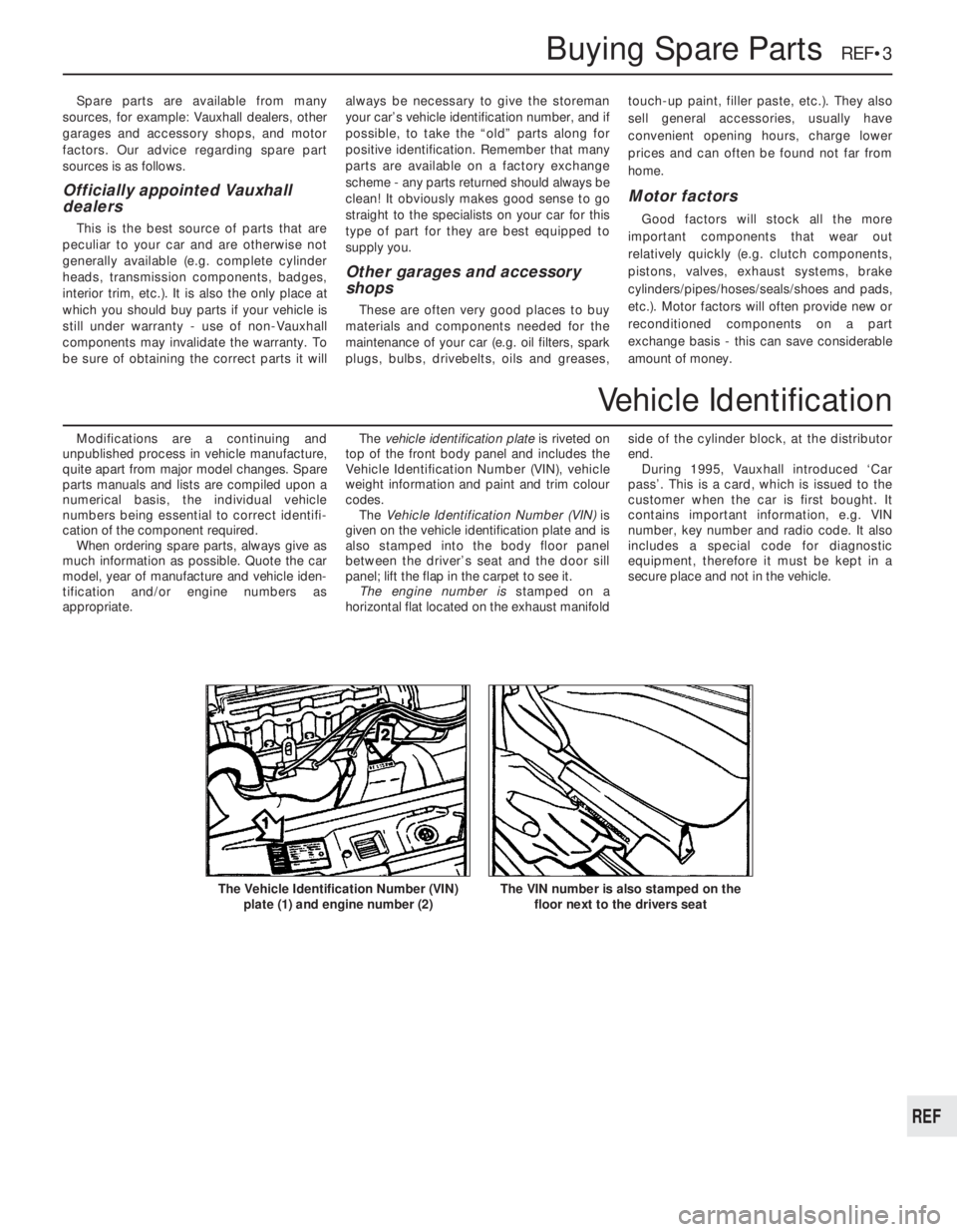
The Vehicle Identification Number (VIN) is
given on the vehicle identification plate and is
also stamped into the body floor panel
between the driver’s seat and the door sill
panel; lift the flap in the carpet to see it.
The engine number is stamped on a
horizontal flat located on the exhaust manifoldside of the cylinder block, at the distributor
end.
During 1995, Vauxhall introduced ‘Car
pass’. This is a card, which is issued to the
customer when the car is first bought. It
contains important information, e.g. VIN
number, key number and radio code. It also
includes a special code for diagnostic
equipment, therefore it must be kept in a
secure place and not in the vehicle.
Buying Spare Parts REF•3
The VIN number is also stamped on the
floor next to the drivers seatThe Vehicle Identification Number (VIN)
plate (1) and engine number (2)
REF
Vehicle Identification
Page 245 of 525
REF•6Tools and Working Facilities
Introduction
A selection of good tools is a fundamental
requirement for anyone contemplating the
maintenance and repair of a motor vehicle.
For the owner who does not possess any,
their purchase will prove a considerable
expense, offsetting some of the savings made
by doing-it-yourself. However, provided that
the tools purchased meet the relevant national
safety standards and are of good quality, they
will last for many years and prove an
extremely worthwhile investment.
To help the average owner to decide which
tools are needed to carry out the various tasks
detailed in this manual, we have compiled
three lists of tools under the following
headings: Maintenance and minor repair,
Repair and overhaul, and Special. Newcomers
to practical mechanics should start off with
the Maintenance and minor repairtool kit, and
confine themselves to the simpler jobs around
the vehicle. Then, as confidence and
experience grow, more difficult tasks can be
undertaken, with extra tools being purchased
as, and when, they are needed. In this way, a
Maintenance and minor repairtool kit can be
built up into a Repair and overhaultool kit over
a considerable period of time, without any
major cash outlays. The experienced do-it-
yourselfer will have a tool kit good enough for
most repair and overhaul procedures, and will
add tools from the Specialcategory when it is
felt that the expense is justified by the amount
of use to which these tools will be put.
Maintenance
and minor repair tool kit
The tools given in this list should be
considered as a minimum requirement if
routine maintenance, servicing and minor
repair operations are to be undertaken. We
recommend the purchase of combination
spanners (ring one end, open-ended the
other); although more expensive than open-
ended ones, they do give the advantages of
both types of spanner.
MCombination spanners:
Metric - 8 to 19 mm inclusive
MAdjustable spanner - 35 mm jaw (approx.)
MSpark plug spanner (with rubber insert) -
petrol models
MSpark plug gap adjustment tool - petrol
models
MSet of feeler gauges
MBrake bleed nipple spanner
MScrewdrivers:
Flat blade - 100 mm long x 6 mm dia
Cross blade - 100 mm long x 6 mm dia
MCombination pliers
MHacksaw (junior)
MTyre pump
MTyre pressure gauge
MOil can
MOil filter removal tool
MFine emery cloth
MWire brush (small)
MFunnel (medium size)
Repair and overhaul tool kit
These tools are virtually essential for
anyone undertaking any major repairs to a
motor vehicle, and are additional to those
given in the Maintenance and minor repairlist.
Included in this list is a comprehensive set of
sockets. Although these are expensive, they
will be found invaluable as they are so
versatile - particularly if various drives are
included in the set. We recommend the half-
inch square-drive type, as this can be used
with most proprietary torque wrenches.
The tools in this list will sometimes need to
be supplemented by tools from the Speciallist:
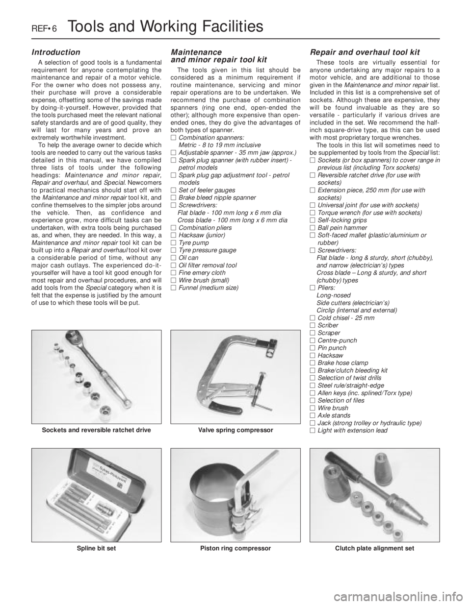
MSockets (or box spanners) to cover range in
previous list (including Torx sockets)
MReversible ratchet drive (for use with
sockets)
MExtension piece, 250 mm (for use with
sockets)
MUniversal joint (for use with sockets)
MTorque wrench (for use with sockets)
MSelf-locking grips
MBall pein hammer
MSoft-faced mallet (plastic/aluminium or
rubber)
MScrewdrivers:
Flat blade - long & sturdy, short (chubby),
and narrow (electrician’s) types
Cross blade – Long & sturdy, and short
(chubby) types
MPliers:
Long-nosed
Side cutters (electrician’s)
Circlip (internal and external)
MCold chisel - 25 mm
MScriber
MScraper
MCentre-punch
MPin punch
MHacksaw
MBrake hose clamp
MBrake/clutch bleeding kit
MSelection of twist drills
MSteel rule/straight-edge
MAllen keys (inc. splined/Torx type)
MSelection of files
MWire brush
MAxle stands
MJack (strong trolley or hydraulic type)
MLight with extension lead
Sockets and reversible ratchet drive
Clutch plate alignment setPiston ring compressorSpline bit set
Valve spring compressor