Page 76 of 1378

These small voltage spikes give the ECU information for calculating
engine speed.
When a large tooth and notch pass the magnetic core of the
sensor, the concentration and collapse of the magnetic field created
induces a higher voltage spike into the sensor pick-up coil windings.
This higher voltage spike indicates to the ECU that a piston will soon
be at TDC (12 teeth later).
The ECU uses speed sensor information for advancing or
retarding ignition timing, dependent upon input from other sensors and
switches.
A/C "ON" Switch
This switch signals the ECU that the A/C system is energized.
This signal is used by the ECU to increase idle speed.
Starter Motor Relay
Although no switch or sensor is used, the ECU requires this
information for fuel enrichment during starting. This information is
passed on the the ECU through the starter motor relay.
Distributor Reference Signal
Although no switch or sensor is used, the ECU requires this
information for ignition timing and fuel supply. This information is
relayed to the ECU through a "synch pulse" provided by the distributor
stator. This allows the ECU to synchronize injector opening with
intake valve opening.
ELECTRONIC CONTROL MODULE (ECM)
The Electronic Control Unit (ECU) is the "brain" of the
engine control system. The ECU is located in the passenger
compartment, under left side of dash to right of steering column.
The ECU senses engine operating conditions, processes input
signals, and controls the various systems that affect vehicle
performance.
DIAGNOSTICS
The engine control system has diagnostic capabilities. Using
System Tester (M.S. 1700), diagnostics can be performed on the system
to more accurately determine faulty components. The diagnostic
connectors are located in the engine compartment at the right shock
tower (or under left side of instrument panel).
NOTE: Information for diagnosing the engine control system using
the System Tester (M.S. 1700) was not available from
manufacturer. Only component testing is provided.
ELECTRONIC SPARK ADVANCE
Based upon engine operating conditions received from the
sensors and switches, the ECU controls spark timing. The ECU triggers
the ignition coil through the ignition control module.
IDLE SPEED CONTROL
Idle speed is controlled by the ECU through the idle speed
stepper motor. A latch relay is used to program the stepper motor for
engine start-up. The relay is located on the right inner fender panel.
See Fig. 1 . The ECU energizes the latch relay when engine is in
cranking mode, and keeps the relay energized for 3-5 seconds after the
engine is stopped. In this way, the stepper motor can provide the
Page 197 of 1378

DRB-II scan tool. When retrieving diagnostic trouble codes
using DRB-II, you must first enter AW4 MENU and then
retrieve diagnostic trouble codes.
NOTE: Ensure TEST 1A - VERIFICATION OF THE COMPLAINT is performed
when trouble shooting the vehicle. This test checks for
diagnostic trouble codes with vehicle stationary and during
road test. See TEST 1A - VERIFICATION OF THE COMPLAINT under
TROUBLE SHOOTING CHARTS.
NOTE: The DRB-II scan tool can be used in several different modes
using manufacturer's instructions to activate system
components and perform several tests on transmission. See
DRB-II OPERATING MODES .
Entering AW4 MENU
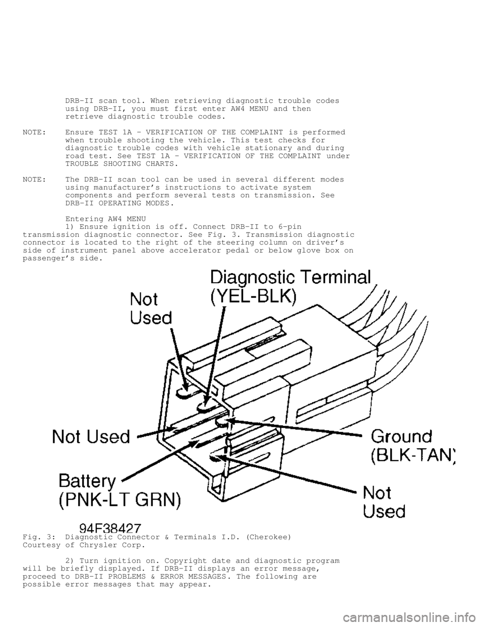
1) Ensure ignition is off. Connect DRB-II to 6-pin
transmission diagnostic connector. See Fig. 3. Transmission diagnostic
connector is located to the right of the steering column on driver's
side of instrument panel above accelerator pedal or below glove box on
passenger's side.
Fig. 3: Diagnostic Connector & Terminals I.D. (Cherokee)
Courtesy of Chrysler Corp.
2) Turn ignition on. Copyright date and diagnostic program
will be briefly displayed. If DRB-II displays an error message,
proceed to DRB-II PROBLEMS & ERROR MESSAGES . The following are
possible error messages that may appear.
Page 272 of 1378
Fig. 125: TCM Connector Terminals I.D., Circuits & Functions
Courtesy of Chrysler Corp.
REMOVAL & INSTALLATION
BRAKE SWITCH
Removal
Remove lower steering column cover or trim panels for access
to brake switch (if necessary). Disconnect brake switch electrical
connector. Thread brake switch from retainer and remove.
Page 273 of 1378

Installation
1) Install brake switch in retainer. Reconnect brake switch
electrical connector.
2) To check brake switch adjustment, slightly depress brake
pedal and note operation of brake switch plunger. Brake switch plunger
should fully extend when brake pedal free play is taken up and brake
application begins.
3) Clearance between brake switch plunger and brake pedal
should be approximately 1/8". If clearance is not within
specification, pull brake pedal rearward as far as possible.
4) Brake pedal should contact brake switch plunger, pushing
brake switch backward in retainer to provide proper adjustment. Ensure
brake lights operate.
5) Recheck clearance between brake switch plunger and brake
pedal with brake pedal depressed and free play taken up. Reinstall
lower steering column cover or trim panels.
NEUTRAL SAFETY SWITCH
NOTE: Neutral safety switch may be referred to as park/neutral or
gear select switch.
Removal
1) Apply parking brake. Raise and support vehicle. Disconnect
electrical connector at neutral safety switch. Pry lock washer tabs
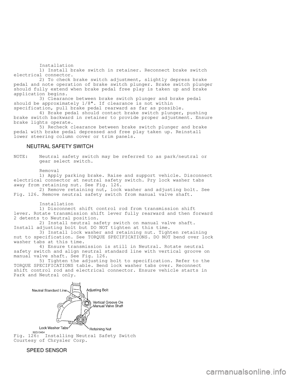
away from retaining nut. See Fig. 126.
2) Remove retaining nut, lock washer and adjusting bolt. See
Fig. 126 . Remove neutral safety switch from manual valve shaft.
Installation
1) Disconnect shift control rod from transmission shift
lever. Rotate transmission shift lever fully rearward and then forward
2 detents to Neutral position.
2) Install neutral safety switch on manual valve shaft.
Install adjusting bolt but DO NOT tighten at this time.
3) Install lock washer and retaining nut. Tighten retaining
nut to specification. See TORQUE SPECIFICATIONS. DO NOT bend over lock
washer tabs at this time.
4) Ensure transmission is still in Neutral. Rotate neutral
safety switch and align neutral standard line with vertical groove on
manual valve shaft. See Fig. 126.
5) Tighten the adjusting bolt to specification. Refer to the
TORQUE SPECIFICATIONS table. Bend lock washer tabs over. Reconnect
shift control rod and electrical connector. Ensure vehicle starts in
Park and Neutral only.
Fig. 126: Installing Neutral Safety Switch
Courtesy of Chrysler Corp.
SPEED SENSOR
Page 487 of 1378
Rear Window Defogger Relay Under instrument panel, to
right of steering column.
Rear Wiper Relay In tailgate, next to wiper
motor.
Starter Relay (Graphic 1) Behind right headlight, on
wheelwell.
Page 493 of 1378
Ignition Control Module In engine compartment, on
right wheelwell.
Intermittent Wiper Module Under left side of dash, above
brake pedal.
Keyless Entry Receiver Between sun visors.
Maint. Reminder Module Under dash, to right of
steering column.
Sentinel Light Module Under left side of dash, near
headlight switch.
Page 494 of 1378
System Sentry Control Module Under dash, to right of
steering column.
Transmission Control Module Under right side of instrument
panel.
������������������\
������������������\
������������������\
������������������\
������������������\
������������������\
������������������\
�������������
MOTORS
������������������\
������������������\
������������������\
������������������\
������������������\
������������������\
������������������\
�������������
Component Component Location
A/C-Heater Blower Motor In evaporator housing.
Page 845 of 1378

IG NIT IO N S W IT C H & L O CK C YLIN DER
�
1988 J e ep C hero ke e
1988 Ignition Switch & Lock Cylinders
JEEP
DESCRIPTION
The ignition switch and lock cylinder is typically mounted on
the steering column and actuated by an ignition key.
SERVICING
To gain access to ignition components on Jeep vehicles, the
steering column must be removed or lowered and the turn signal switch
must be removed.
CAUTION: The lock plate is held by high spring pressure. DO NOT
remove snap ring without using a compressor tool. If the
steering shaft has standard threads, use Compressor Tool
(J-23653); if the shaft has metric threads use Metric
Forcing Screw (J-23653-4).
CAUTION: Special care must be taken to avoid bumping, jolting or
hammering on the steering shaft and gearshift tube.
REMOVAL & INSTALLATION
LOCK CYLINDER
Removal
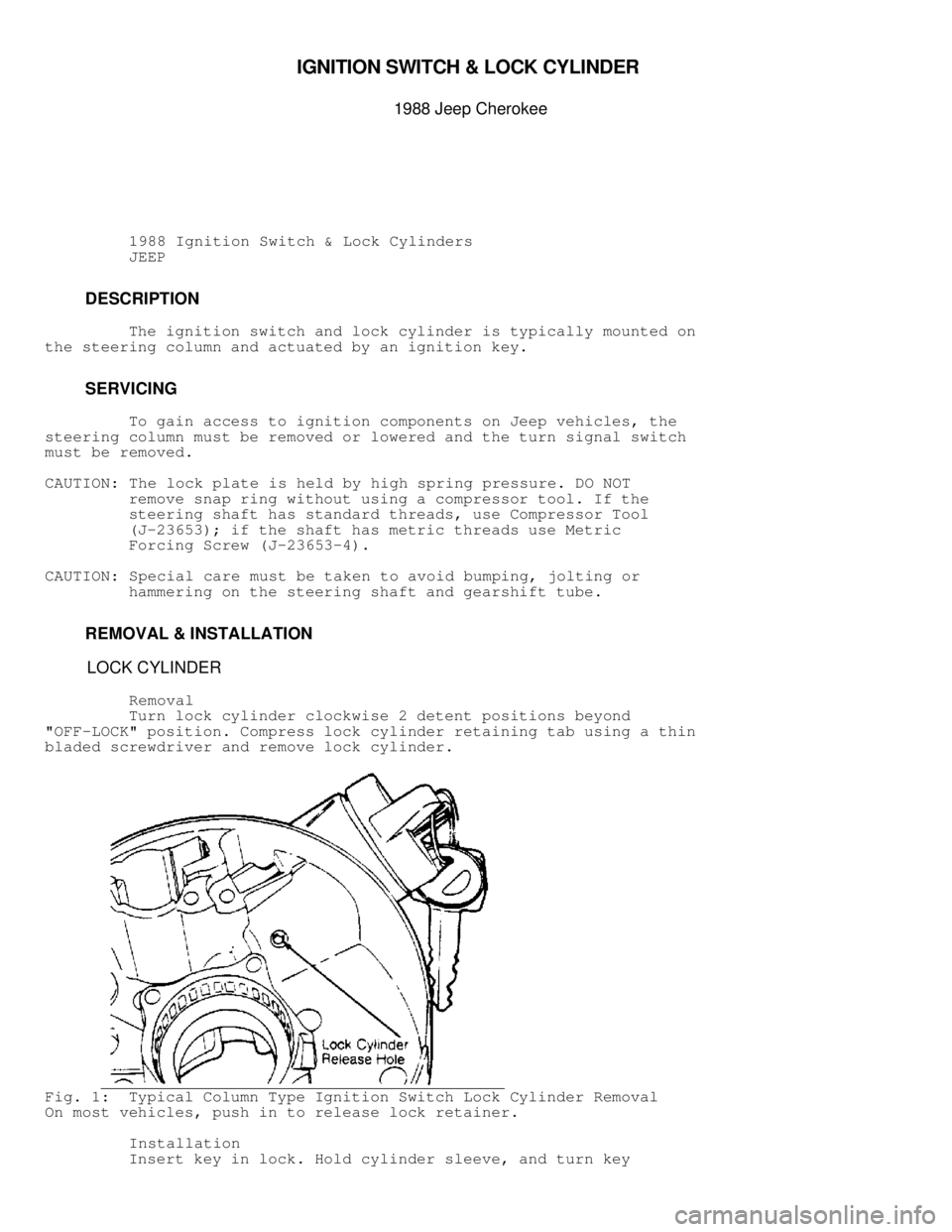
Turn lock cylinder clockwise 2 detent positions beyond
"OFF-LOCK" position. Compress lock cylinder retaining tab using a thin
bladed screwdriver and remove lock cylinder.
Fig. 1: Typical Column Type Ignition Switch Lock Cylinder Removal
On most vehicles, push in to release lock retainer.
Installation
Insert key in lock. Hold cylinder sleeve, and turn key