Page 884 of 1378

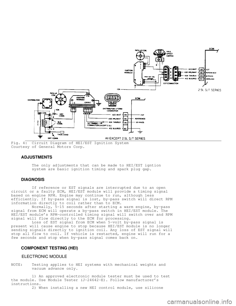
Fig. 4: Circuit Diagram of HEI/EST Ignition System
Courtesy of General Motors Corp.
ADJUSTMENTS
The only adjustments that can be made to HEI/EST igntion
system are basic ignition timing and spark plug gap.
DIAGNOSIS
If reference or EST signals are interrupted due to an open
circuit or a faulty ECM, HEI/EST module will provide a timing signal
based on engine RPM. Engine may continue to run, although less
efficiently. If by-pass signal is lost, by-pass switch will direct RPM
information directly to coil rather than to ECM.
Normally, 5-15 seconds after starting a warm engine, by-pass
signal from ECM will operate a by-pass switch in HEI/EST module. The
HEI/EST module's RPM-controlled timing signal will switch over and RPM
signal will flow directly to the ECM for processing.
Loss of EST signal from ECM when 5-volt by-pass signal is
present will cause engine to stop because HEI/EST module is no longer
sending signals directly to ignition coil. Any loss of EST signal will
stop all flow to coil. If vehicle is restarted, engine will run for a
few seconds and stop when by-pass signal comes back on.
COMPONENT TESTING (HEI)
ELECTRONIC MODULE
NOTE: Testing applies to HEI systems with mechanical weights and
vacuum advance only.
1) An approved electronic module tester must be used to test
the module. Use Module Tester (J-24642-E). Follow manufacturer's
instructions.
2) When installing a new HEI control module, use silicone
Page 891 of 1378
system. For testing, see appropriate IGNITION SYSTEM CHECK
flow chart in COMPUTERIZED ENGINE CONTROLS section. For
diagnosis of HEI system, refer to following diagnostic
chart. See Fig. 11.
Fig. 11: Ignition Sys Check (HEI Only), Testing applies to HEI
sys with mechanical weights and vacuum advance.
Courtesy of General Motors Corp.
OVERHAUL
Page 902 of 1378

MAIN TE N AN CE IN FO RM ATIO N
�
1988 J e ep C hero ke e
1984-88 MAINTENANCE
AMC/Jeep Maintenance Information
Jeep; Cherokee,
Wagoneer
* PLEASE READ THIS FIRST *
NOTE: For scheduled maintenance intervals and the related fluid
capacities, fluid specifications and labor times for major
service intervals, see SCHEDULED SERVICES article below:
* SCHEDULED SERVICES - GASOLINE
* SCHEDULED SERVICES - DIESEL ENGINES - NORMAL (1985-87)
Warranty information and specifications for fluid
capacities, lubrication specifications, wheel and tire size,
and battery type are covered in this article.
MODEL IDENTIFICATION
VIN LOCATION
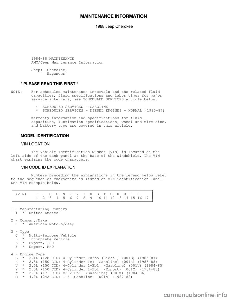
The Vehicle Identification Number (VIN) is located on the
left side of the dash panel at the base of the windshield. The VIN
chart explains the code characters.
VIN CODE ID EXPLANATION
Numbers preceding the explanations in the legend below refer
to the sequence of characters as listed on VIN identification label.
See VIN example below.
������������������\
������������������\
������������������\
������������������\
������������������\
������������������\
����������������� �
(VIN) 1 J C U N 7 7 1 X G T 0 0 0 0 0 1 �
�
1 2 3 4 5 6 7 8 9 10 11 12 13 14 15 16 17 �
�
������������������\
������������������\
������������������\
������������������\
������������������\
������������������\
���������������
1 - Manufacturing Country
1
* United States
2 - Company/Make
J * American Motors/Jeep
3 - Type
C * Multi-Purpose Vehicle
D * Incomplete Vehicle
E * Export, LHD
F * Export, RHD
4 - Engine Type
B * 2.1L (128 CID) 4-Cylinder Turbo (Diesel) (001B) (1985-87)
H * 2.5L (150 CID) 4-Cylinder TBI (Gasoline) (001H) (1986-88)
U * 2.5L (150 CID) 4-Cylinder 1-Bbl. (Gasoline) (001U) (1984-85)
Y * 2.5L (150 CID) 4-Cylinder 1-Bbl. (Export) (001Y) (1984-85)
W * 2.8L (171 CID) V6 2-Bbl. (Gasoline) (001W) (1984-86)
M * 4.0L (242 CID) I-6 (Gasoline) (001M) (1987-88)
Page 904 of 1378

* Cold Climate Operation
* Towing Or Heavily Loading
* Severe Dust Conditions
* Sustained High Speed Operation
* Off-Road Driving
* Hot Weather, Stop-And-Go Driving
* Extensive Idling Conditions (Taxi Or Delivery Type Service)
Normal Service
* Driven More Than 10 Miles Daily
* No Severe Service Operating Conditions
CAMSHAFT TIMING BELT REPLACEMENT INFORMATION (TURBO-DIESEL)
CAUTION: Failure to replace a faulty camshaft timing belt may result
in serious engine damage.
The condition of camshaft drive belts should always be
checked on vehicles which have more than 50,000 miles. Although some
manufacturers do not recommend belt replacement at a specified
mileage, others require it at 60,000-100,000 miles. A camshaft drive
belt failure may cause extensive damage to internal engine components
on most engines, although some designs do not allow piston-to-valve
contact. These designs are often called "Free Wheeling".
Many manufacturers changed their maintenance and warranty
schedules in the mid-1980's to reflect timing belt inspection and/or
replacement at 50,000-60,000 miles. Most service interval schedules
reflect these changes.
Belts or components should be inspected and replaced if any
of the following conditions exist:
* Cracks Or Tears In Belt Surface
* Missing, Damaged, Cracked Or Rounded Teeth
* Oil Contamination
* Damaged Or Faulty Tensioners
* Incorrect Tension Adjustment
SERVICE LABOR TIMES
SERVICE LABOR TIMES TABLE (HOURS)������������������\
������������������\
������������������\
������������������\
������������������\
������������������\
������������������\
���
( 1) 30,000 60,000
Application Mile Service Mile Service
2.1L (Turbo Diesel)
Automatic Transmission ........... 4.3 ................ 4.5
Manual Transmission .............. 3.6 ................ 3.8
2.5L
Automatic Transmission ........... 5.6 ................ 3.5
Manual Transmission .............. 4.9 ................ 3.5
2.8L
Automatic Transmission ........... 5.8 ................ 3.7
Manual Transmission .............. 5.1 ................ 3.7
4.0L
Automatic Transmission ........... 5.7 ................ 3.6
Manual Transmission .............. 5.0 ................ 3.6
( 1) - Add .8 hr. for vehicles equipped with 4WD.
������������������\
������������������\
������������������\
������������������\
������������������\
������������������\
������������������\
���
Page 905 of 1378
SERVICE POINT LOCATIONS
Fig. 1: Service Point Locations (Typical)
Courtesy of American Motors Corp.
NOTE: The 2.1L Turbo-Diesel engine has two (2) oil drain plugs
ADDITIONAL SERVICE INFORMATION
Fig. 2: Water Separator (Diesel)
Courtesy of American Motors Corp.
NOTE: For more information regarding 2.1L Turbo-Diesel engine
service refer to the TUNE-UP - DIESEL article in
Page 906 of 1378

the ENGINE PERFORMANCE section.
Fuel filter should be drained whenever "WATER IN FUEL"
warning light glows. Diesel fuel can damage asphalt and
painted surfaces. Always place a drain pan under fuel filter
to collect contaminated fuel. See Fig. 2.
1) Stop vehicle and turn engine off. Attach a long piece
of tubing to drain cock outlet. Place end of drain hose into
drain pan. Open filter assembly vent valve (Black + shaped
knob) and drain cock.
2) Drain approximately 1/2 pint (.24 Liters) from fuel
filter. Close vent valve and drain cock. Start engine and
check for leaks. If "WATER IN FUEL" warning lamp comes on
again, remove water contaminated fuel from fuel lines and
fuel tank.
WARNING: DO NOT bleed fuel lines on hot engine, as high exhaust
temperatures could cause fire. Use care when bleeding fuel
lines, as fuel is under extreme pressure and could penetrate
skin, causing personal injury. Wear safety goggles and
protective clothing when bleeding fuel lines.
CAUTION: DO NOT drain fuel/water separator when engine is running or
hot. Allow engine to cool before draining. Verify that the
WATER IN FUEL light on instrument panel is OFF.
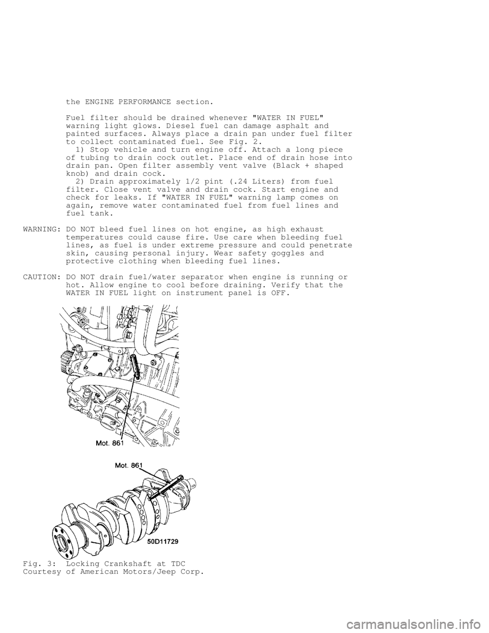
Fig. 3: Locking Crankshaft at TDC
Courtesy of American Motors/Jeep Corp.
Page 908 of 1378
Fig. 6: Valve Layout
Courtesy of American Motors/Jeep Corp.
NOTE: For more information regarding 2.1L Turbo-Diesel engine
service refer to the 2.1L 4-CYL TURBO DIESEL - VIN [B]
Page 909 of 1378
article in the ENGINE MECHANICAL section.
Fig. 7: Hoist Lift Point Locations
Courtesy of American Motors Corp.
NOTE: For more information regarding jacking and hoisting refer
to the JACKING & HOISTING article in the