1988 JEEP CHEROKEE 6 cylinder
[x] Cancel search: 6 cylinderPage 610 of 1378

completion of the inspection. Magnetic particle inspection applies to
ferrous materials only.
PENETRANT INSPECTION
Zyglo
The Zyglo process coats the material with a fluorescent dye
penetrant. The part is often warmed to expand cracks that will be
penetrated by the dye. When the coated part is subjected to inspection
with a blacklight, a crack will glow brightly. Developing solution
is often used to enhance results. Parts made of any material, such as
aluminum cylinder heads or plastics, may be tested using this process.
Dye Check
Penetrating dye is sprayed on the previously cleaned
component. Dye is left on component for 5-45 minutes, depending upon
material density. Component is then wiped clean and sprayed with a
developing solution. Surface cracks will show up as a bright line.
ULTRASONIC INSPECTION
If an expensive part is suspected of internal cracking,
Ultrasonic testing is used. Sound waves are used for component
inspection.
X-RAY INSPECTION
This form of inspection is used on highly stressed
components. X-ray inspection maybe used to detect internal and
external flaws in any material.
PRESSURE TESTING
Cylinder heads can be tested for cracks using a pressure
tester. Pressure testing is performed by plugging all but one of the
holes in the head and injecting air or water into the open passage.
Leaks are indicated by the appearance of wet or damp areas when using
water. When air is used, it is necessary to spray the head surface
with a soap solution. Bubbles will indicate a leak. Cylinder head may
also be submerged in water heated to specified temperature to check
for cracks created during heat expansion.
CLEANING PROCEDURES
* PLEASE READ THIS FIRST *
NOTE: Always refer to appropriate engine overhaul article in the
ENGINES section for complete overhaul procedures and
specifications for the vehicle being repaired.
GENERAL
All components of an engine do not have the same cleaning
requirements. Physical methods include bead blasting and manual
removal. Chemical methods include solvent blast, solvent tank, hot
tank, cold tank and steam cleaning of components.
BEAD BLASTING
Manual removal of deposits may be required prior to bead
blasting, followed by some other cleaning method. Carbon, paint and
Page 611 of 1378

rust may be removed using bead blasting method. Components must be
free of oil and grease prior to bead blasting. Beads will stick to
grease or oil soaked areas causing area not to be cleaned.
Use air pressure to remove all trapped residual beads from
components after cleaning. After cleaning internal engine parts made
of aluminum, wash thoroughly with hot soapy water. Component must be
thoroughly cleaned as glass beads will enter engine oil resulting in
bearing damage.
CHEMICAL CLEANING
Solvent tank is used for cleaning oily residue from
components. Solvent blasting sprays solvent through a siphon gun using
compressed air.
The hot tank, using heated caustic solvents, is used for
cleaning ferrous materials only. DO NOT clean aluminum parts such as
cylinder heads, bearings or other soft metals using the hot tank.
After cleaning, flush parts with hot water.
A non-ferrous part will be ruined and caustic solution will
be diluted if placed in the hot tank. Always use eye protection and
gloves when using the hot tank.
Use of a cold tank is for cleaning of aluminum cylinder
heads, carburetors and other soft metals. A less caustic and unheated
solution is used. Parts may be lift in the tank for several hours
without damage. After cleaning, flush parts with hot water.
Steam cleaning, with boiling hot water sprayed at high
pressure, is recommended as the final cleaning process when using
either hot or cold tank cleaning.
COMPONENT CLEANING
* PLEASE READ THIS FIRST *
NOTE: Always refer to appropriate engine overhaul article in the
ENGINES section for complete overhaul procedures and
specifications for the vehicle being repaired.
SHEET METAL PARTS
Examples of sheet metal parts are the rocker covers, front
and side covers, oil pan and bellhousing dust cover. Glass bead
blasting or hot tank may be used for cleaning.
Ensure all mating surfaces are flat. Deformed surfaces should
be straightened. Check all sheet metal parts for cracks and dents.
INTAKE & EXHAUST MANIFOLDS
Using solvent cleaning or bead blasting, clean manifolds for
inspection. If the intake manifold has an exhaust crossover, all
carbon deposits must be removed. Inspect manifolds for cracks, burned
or eroded areas, corrosion and damage to fasteners.
Exhaust heat and products of combustion cause threads of
fasteners to corrode. Replace studs and bolts as necessary. On "V"
type intake manifolds, the sheet metal oil shield must be removed for
proper cleaning and inspection. Ensure that all manifold parting
surfaces are flat and free of burrs.
CYLINDER HEAD REPLACEMENT
* PLEASE READ THIS FIRST *
Page 612 of 1378
NOTE: Always refer to appropriate engine overhaul article in the
ENGINES section for complete overhaul procedures and
specifications for the vehicle being repaired.
REMOVAL
Remove intake and exhaust manifolds and valve cover. Cylinder
head and camshaft carrier bolts (if equipped), should be removed only
when the engine is cold. On many aluminum cylinder heads, removal
while hot will cause cylinder head warpage. Mark rocker arm or
overhead cam components for location.
Remove rocker arm components or overhead cam components.
Components must be installed in original location. Individual design
rocker arms may utilize shafts, ball-type pedestal mounts or no rocker
arms. For all design types, wire components together and identify
according to the corresponding valve. Remove cylinder head bolts.
Note length and location. Some applications require cylinder head
bolts be removed in proper sequence to prevent cylinder head damage.
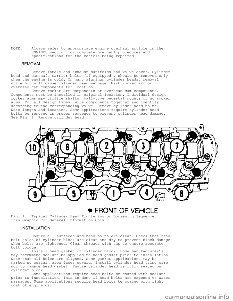
See Fig. 1 . Remove cylinder head.
Fig. 1: Typical Cylinder Head Tightening or Loosening Sequence
This Graphic For General Information Only
INSTALLATION
Ensure all surfaces and head bolts are clean. Check that head
bolt holes of cylinder block are clean and dry to prevent block damage
when bolts are tightened. Clean threads with tap to ensure accurate
bolt torque.
Install head gasket on cylinder block. Some manufacturer's
may recommend sealant be applied to head gasket prior to installation.
Note that all holes are aligned. Some gasket applications may be
marked so certain area faces upward. Install cylinder head using care
not to damage head gasket. Ensure cylinder head is fully seated on
cylinder block.
Some applications require head bolts be coated with sealant
prior to installation. This is done if head bolts are exposed to water
passages. Some applications require head bolts be coated with light
coat of engine oil.
Page 613 of 1378

Install head bolts. Head bolts should be tightened in proper
steps and sequence to specification. See Fig. 1. Install remaining
components. Tighten all bolts to specification. Adjust valves if
required. See VALVE ADJUSTMENT in this article.
NOTE: Some manufacturers require that head bolts be retightened
after specified amount of operation. This must be done to
prevent head gasket failure.
VALVE ADJUSTMENT
Engine specifications will indicate valve train clearance and
temperature at which adjustment is to be made on most models. In most
cases, adjustment will be made with a cold engine. In some cases, both
a cold and a hot clearance will be given for maintenance convenience.
On some models, adjustment is not required. Rocker arms are
tightened to specification and valve lash is automatically set. On
some models with push rod actuated valve train, adjustment is made at
push rod end of rocker arm while other models do not require
adjustment.
Clearance will be checked between tip of rocker arm and tip
of valve stem in proper sequence using a feeler gauge. Adjustment is
made by rotating adjusting screw until proper clearance is obtained.
Lock nut is then tightened. Engine will be rotated to obtain all valve
adjustments to manufacturer's specifications.
Some models require hydraulic lifter to be bled down and
clearance measured. Different length push rods can be used to obtain
proper clearance. Clearance will be checked between tip of rocker arm
and tip of valve stem in proper sequence using a feeler gauge.
On overhead cam engines designed without rocker arms actuate
valves directly on a cam follower. A hardened, removable disc is
installed between the cam lobe and lifter. Clearance will be checked
between cam heel and adjusting disc in proper sequence using a feeler
gauge. Engine will be rotated to obtain all valve adjustments.
On overhead cam engines designed with rocker arms, adjustment
is made at push rod end of rocker arm. Ensure that the valve to be
adjusted is riding on the heel of the cam on all engines. Clearance
will be checked between tip of rocker arm and tip of valve stem in
proper sequence using a feeler gauge. Adjustment is made by rotating
adjusting screw until proper clearance is obtained. Lock nut is then
tightened. Engine will be rotated to obtain all valve adjustments to
manufacturer's specifications.
CYLINDER HEAD OVERHAUL
* PLEASE READ THIS FIRST *
NOTE: Always refer to appropriate engine overhaul article in the
ENGINES section for complete overhaul procedures and
specifications for the vehicle being repaired.
DISASSEMBLY
Mark valves for location. Using valve spring compressor,
compress valve springs. Remove valve locks. Carefully release spring
compressor. Remove retainer or rotator, valve spring, spring seat and
valve. See Fig. 2.
Page 614 of 1378
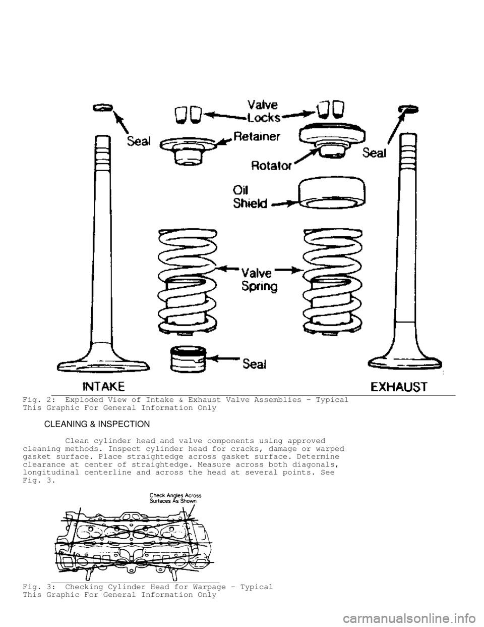
Fig. 2: Exploded View of Intake & Exhaust Valve Assemblies - Typical
This Graphic For General Information Only
CLEANING & INSPECTION
Clean cylinder head and valve components using approved
cleaning methods. Inspect cylinder head for cracks, damage or warped
gasket surface. Place straightedge across gasket surface. Determine
clearance at center of straightedge. Measure across both diagonals,
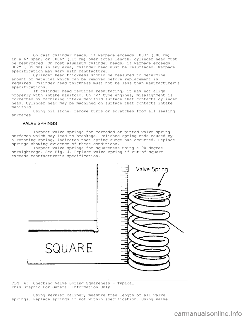
longitudinal centerline and across the head at several points. See
Fig. 3 .
Fig. 3: Checking Cylinder Head for Warpage - Typical
This Graphic For General Information Only
Page 615 of 1378
On cast cylinder heads, if warpage exceeds .003" (.08 mm)
in a 6" span, or .006" (.15 mm) over total length, cylinder head must
be resurfaced. On most aluminum cylinder heads, if warpage exceeds .
002" (.05 mm) in any area, cylinder head must be resurfaced. Warpage
specification may vary with manufacturer.
Cylinder head thickness should be measured to determine
amount of material which can be removed before replacement is
required. Cylinder head thickness must not be less than manufacturer's
specifications.
If cylinder head required resurfacing, it may not align
properly with intake manifold. On "V" type engines, misalignment is
corrected by machining intake manifold surface that contacts cylinder
head. Cylinder head may be machined on surface that contacts intake
manifold.
Using oil stone, remove burrs or scratches from all sealing
surfaces.
VALVE SPRINGS
Inspect valve springs for corroded or pitted valve spring
surfaces which may lead to breakage. Polished spring ends caused by
a rotating spring, indicates that spring surge has occurred. Replace
springs showing evidence of these conditions.
Inspect valve springs for squareness using a 90 degree
straightedge. See Fig. 4. Replace valve spring if out-of-square
exceeds manufacturer's specification.
Fig. 4: Checking Valve Spring Squareness - Typical
This Graphic For General Information Only
Using vernier caliper, measure free length of all valve
springs. Replace springs if not within specification. Using valve
Page 616 of 1378
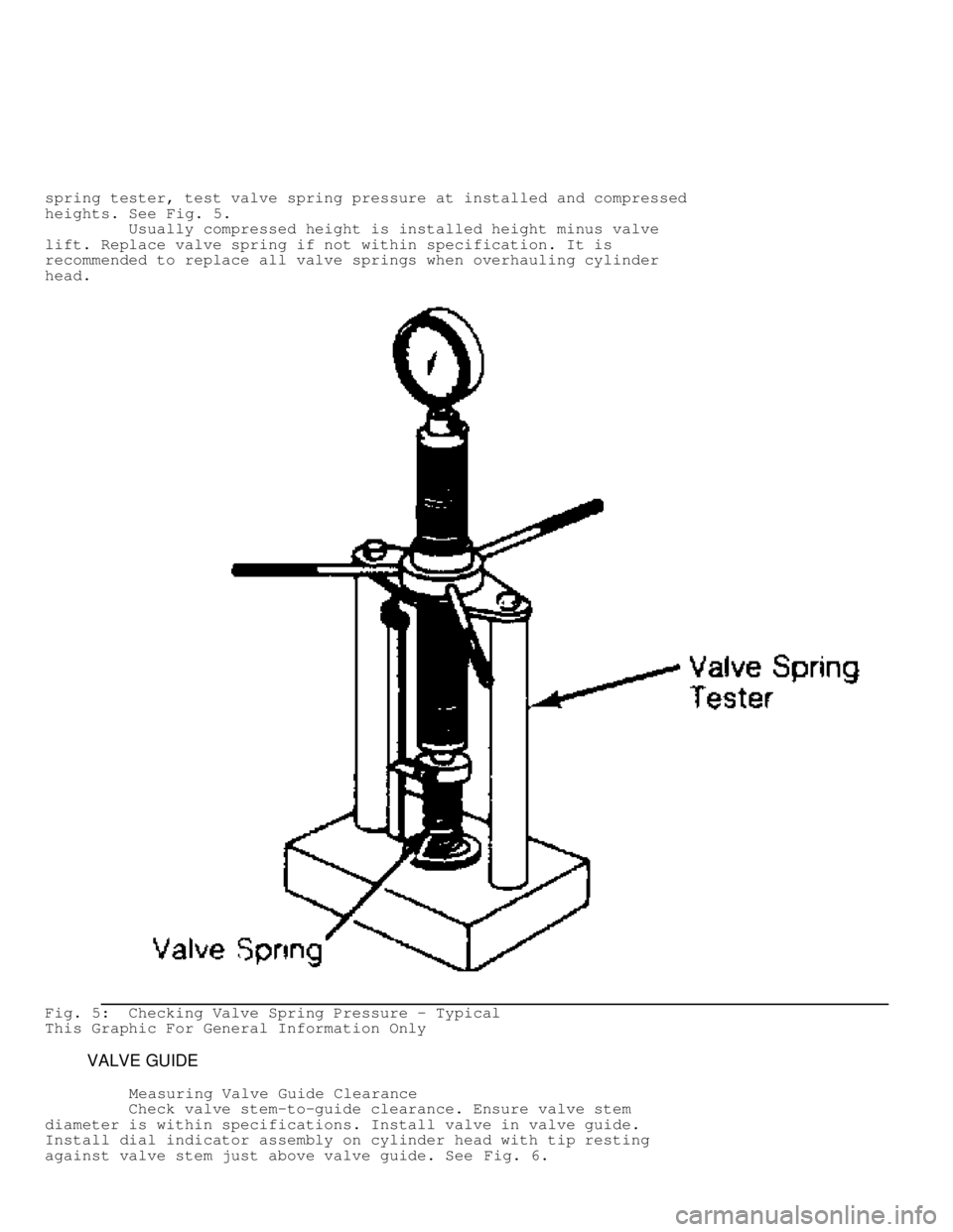
spring tester, test valve spring pressure at installed and compressed
heights. See Fig. 5.
Usually compressed height is installed height minus valve
lift. Replace valve spring if not within specification. It is
recommended to replace all valve springs when overhauling cylinder
head.
Fig. 5: Checking Valve Spring Pressure - Typical
This Graphic For General Information Only
VALVE GUIDE
Measuring Valve Guide Clearance
Check valve stem-to-guide clearance. Ensure valve stem
diameter is within specifications. Install valve in valve guide.
Install dial indicator assembly on cylinder head with tip resting
against valve stem just above valve guide. See Fig. 6.
Page 619 of 1378
cylinder head design and type of metal used.
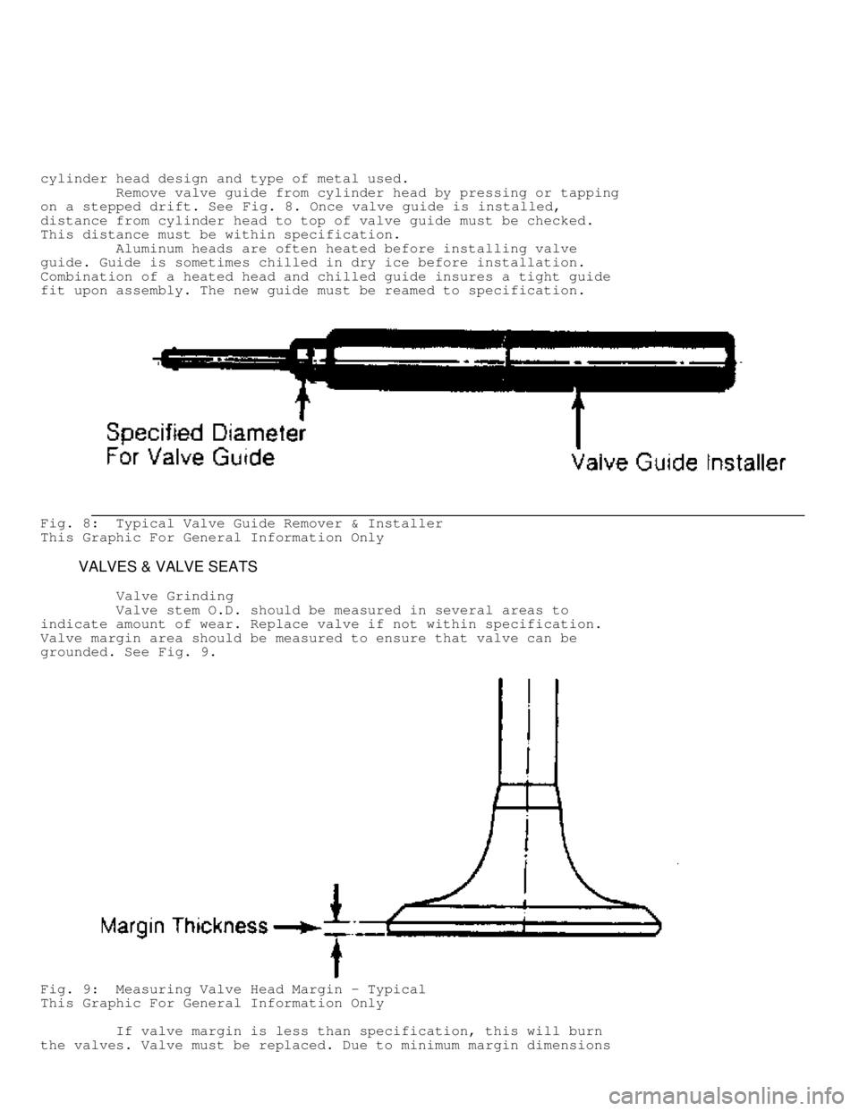
Remove valve guide from cylinder head by pressing or tapping
on a stepped drift. See Fig. 8. Once valve guide is installed,
distance from cylinder head to top of valve guide must be checked.
This distance must be within specification.
Aluminum heads are often heated before installing valve
guide. Guide is sometimes chilled in dry ice before installation.
Combination of a heated head and chilled guide insures a tight guide
fit upon assembly. The new guide must be reamed to specification.
Fig. 8: Typical Valve Guide Remover & Installer
This Graphic For General Information Only
VALVES & VALVE SEATS
Valve Grinding
Valve stem O.D. should be measured in several areas to
indicate amount of wear. Replace valve if not within specification.
Valve margin area should be measured to ensure that valve can be
grounded. See Fig. 9.
Fig. 9: Measuring Valve Head Margin - Typical
This Graphic For General Information Only
If valve margin is less than specification, this will burn
the valves. Valve must be replaced. Due to minimum margin dimensions