1988 FIAT TEMPRA weight
[x] Cancel search: weightPage 91 of 171
Q Step 2: Before starting the engine, make sure all your
electrical connections are sound and your fuel, oil and coolant
connections are correct and secure.
Q Step 3: Run the engine to working temperature and then
allow to cool. Re-check all fluid levels.
Job 20. Diesel engine.
Mountings - replacement.
See
Job
12
and Job
18,
Step 20
Job 21. Diesel engine/
transmission (removed from car)
- separation.
Q Step 1: Remove the starter motor.
• Step 2: On the turbo version, undo the flange bolts see
Job
18,
Step 16A and withdraw the drive-shaft extension, if
still
fitted.
Q Step 3: Unbolt and remove the rear engine plate and the
gearbox, being careful to support the gearbox weight as it is
withdrawn.
Job 22. Diesel engine/
transmission (removed from car)
- reconnection.
Q Step 1: Before proceeding, check the condition of the
clutch and
its release mechanism. Make sure the driven plate
is
properly centred on the flywheel
-
see PART B: TRANS-
MISSION.
Q Step 2: Now reverse the order of separation, but be
careful when
engaging the gearbox input shaft with the
clutch
driven plate that you don't 'hang' its weight on the
splines.
Also,
see
Job 11.
Job 23. Diesel engine -
dismantling.
This Job should
be read in conjunction with Job 5 The
engines are
broadly similar although the information given in
this Job takes
priority for diesel engines. It is MOST
IMPORTANT that you read the FACT FILE on page 84.
SAFETY FIRST!
•
The inside
of diesel engines are particularly filthy
places!
•
Old diesel
oil
is
carcinogenic!
•
Wear suitable
impervious gloves!
I
• Step 1: Remove the timing belt and cylinder head. See
Jobs
13
and 14.
Q Step 2: Remove the alternator, water pump and
thermostat housing distribution pipe.
• Step 3: Remove the crankshaft timing belt sprocket.
Q INSIDE INFORMATION! Note that the bolt securing
the crankshaft sprocket has a left-hand thread and must
be undone clockwise. D
• Step 4: Unbolt the timing belt tensioner and idler pulleys.
• Step 5: Remove the injection pump sprocket.
Q INSIDE INFORMATION! You will need two FIAT tools
for this operation. One (No. 1860473000) is to prevent
the sprocket from turning when undoing the nut, and
the other (extractor No. 1842128000) to pull the sprocket
from the injection pump shaft. Alternatively it may be
possible to improvise a means of preventing sprocket
rotation, and a suitable three-leg puller may be carefully
used to withdraw the sprocket. Take care not to lose the
pump shaft Woodruff key. B
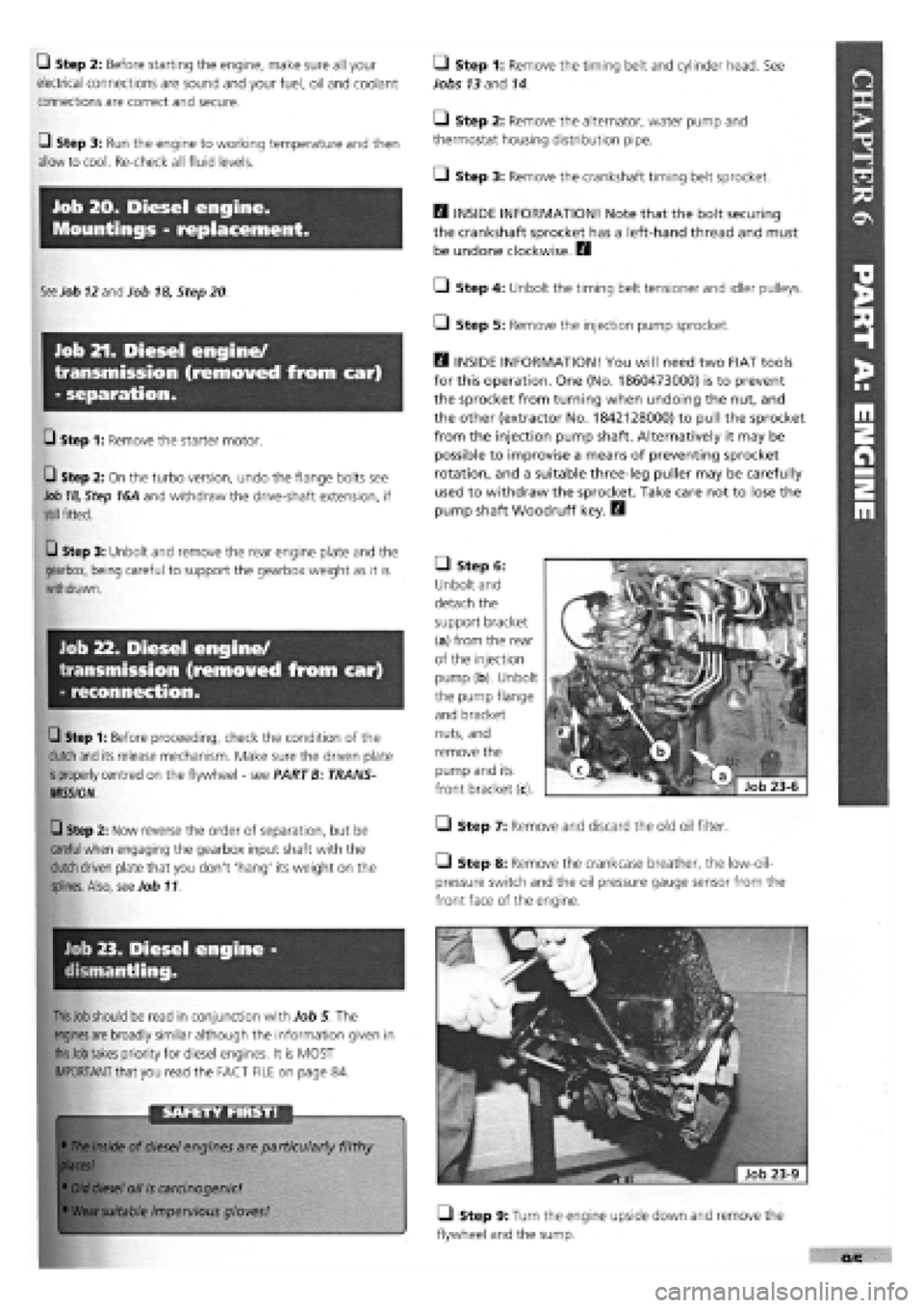
• Step 6:
Unbolt and
detach the
support bracket
(a) from the rear
of the injection
pump (b). Unbolt
the pump flange
and bracket
nuts, and
remove the
pump and its
front bracket (c).
• Step 7: Remove and discard the old oil filter.
Step 8: Remove the crankcase breather, the low-oil-
pressure switch and the oil pressure gauge sensor from the
front face of the engine.
• Step 9: Turn the engine upside down and remove the
flywheel and the sump.
Page 95 of 171

• Step 2: Remove the bonnet. Disconnect and remove the
battery.
0 Step 3: Drain the oil from the transmission.
0 Step 4: Disconnect the clutch cable or remove the slave
cylinder, if hydraulic, from the top of the gearbox.
• Step 13: Disconnect the
gearchange rods at the gearbox
(arrowed).
O Step 14: Remove the trans-
mission mounting and bracket
assembly.
Job 2. Transmission refitting
(with engine in car).
/ a 5tep1S: • SLjpp°n the
'' £/ gearbox in such a way that
when disconnecting, it can
be withdrawn smoothly and without 'hanging' on the
engine. A trolley jack might do the job nicely.
• Step 16:
Undo the gearbox
to engine fixing
bolts...
• Step 17: ...slide the
box back until it's clear of
the clutch and lower it to
the ground using a
hydraulic stand or trolley
jack.
IMPORTANT NOTE: Refer to PART A: ENGINE, Jobs 8
and 9 in connection with this Job.
• Step 1: Refitting is the reverse of the removal work
carried out in Job 1 but bear in mind the following:
Q Step 2: Centralise the clutch driven plate, if it has been
disturbed. See Job 3.
• Step 3: NON-HYDRAULIC CLUTCHES ONLY. Adjust the
clutch cable. See Job 4
Q Step 6: Raise the front of the car and support securely on
axle stands.
Remove the road wheels and the previously
slackened hub nuts.
Q Step 7: Remove the wheel arch protective shields.
Q Step 8: Disconnect the speedometer cable from the
gearbox. (If digital instrumentation, disconnect the wiring
from
the sender unit.)
Q Step 9: Disconnect and remove the starter motor and
unplug
the reverse light connector and the earth lead from
the
transmission housing.
Q Step 10: Undo the trackrod ends securing nuts and use a
suitable 'splitter' tool to part the balljoints from the steering
arms.
Slacken the drive-shaft inner boot securing clips. Undo
the pinch
bolts fixing the stub axles to the suspension struts,
pull
the stub axles clear and extract the drive-shafts.
0 Step 11: Support the engine at the gearbox end, just
taking
the weight as described in Step 1.
Q Step 12: Remove the central power unit support (a), the
flywheel guard (b) and the exhaust bracket (c).
• Step 5: With
the
car
still
on the
ground, loosen
the nuts
fixing the
constant velocity
joints
to the hubs.
These require an
enormous force
to be
tightened or
released (see
Chapter 3,
Facts and Figures) and they will have been
staked. There is a severe risk of pulling the car off supports if
you
attempt to undo these nuts while the car is raised off the
ground. Slacken the front wheel nuts.
Job 1-14
Page 100 of 171

Job 11. Drive-shaft inner spider
joint - replacement.
• Step 3: Replace the (split) rubber mounting and refit the
weight.
Job 13. Front hub/bearings -
replacement.
Job 11-1
a - distance - 305 mm b - spider joint c - inner gaiter d - inner bearing seal e
-
vibration damper f
-
outer gaiter
g - circlip h - outer u.j. i - hub mounting spline
• Step 1: Note the arrangement of the inner spider joint
and drive-shaft components.
Q Step 2: Remove the
drive-shaft from the car. See
Job 9.
• Step 3: Remove the
circlip and pull or press the
spider joint from the drive-
shaft.
• Step 4: Remove the inner gaiter (illustration Job
11-1,
part c) from the seal bearing (Job
11-1,
partd). Check the
bearing for wear and smooth operation.
Q Step 5: Replace it if necessary by using a standard type
puller to remove it from the shaft, driving the new one into
position with a suitable length of tubing.
Q Step 6: After obtaining a new spider joint, if necessary,
(available as a complete replacement item from your FIAT
dealership), fit the new gaiter and its retainer to the shaft,
followed by the spider joint and circlip. No lubrication is
required prior to refitting the drive-shaft.
• Step 7: E9 INSIDE INFORMATION! The turbo diesel
uses an inboard CV joint similar to the outer one except
that it has a flange for attachment to the transmission.
(See PART A: ENGINE, Job 18, Step 16A ) Inspect and
replace in the same way as the outer one. The interme-
diate shaft can only be inspected for wear in its bearing
which cannot be removed separately. Therefore, the
whole unit must be changed if defects are found. Q
Job 12. Drive-shaft damper -
replacement.
Refer to Job
11,
Step 1
Q Step 1: A damper is fitted to the right-hand drive-shaft to
prevent vibration in what is a long drive-shaft. The rubber
mounting can disintegrate or become damaged.
Q Step 2: Use an Allen key to separate the two halves of
the weight.
s * You ™yfind *
" U ' necessary to pull out
gently
on the stub axle and at
the
same time tap lightly (so you don't damage the
thread) on the end of the shaft to knock it through.
• Retrieve the stub axle/hub assembly.
Q Step 7: Use a large vice or a press to push the hub out of
the stub axle.
• Step 8: You may have to remove the bearing inner track
from the hub if it comes out with it.
• Step 2: Partly dismantle the front suspension as described
in Job 9. Steps 2 to 6.
• Step 3: Unbolt the brake caliper and support bracket and
tie it clear.
• Step 1: Take note of the components illustrated here.
Also, see PART G: STEERING AND SUSPENSION, Job
12
where this work is described in more detail.
Q Step 4: Unbolt the brake disc and shield.
• Step 5: Undo the track control arm to stub axle pinch
bolt and
withdraw the
balljoint pin from
the stub axle.
• Step 6: Ease
the stub axle
(illustration Job
13-1,
parts d
and c, combined)
off the drive-
shaft splines (Job
11-1,
parti)
leaving the
inboard end of the
mission.
drive-shaft still attached to the trans-
Page 118 of 171
Job 14. Exhaust system -
replacement.
FACT FILE: LAMBDA SENSOR
• The Lambda sensor is very fragile and
should not be knocked or dropped.
• We recommend that a new one is fitted
only by your FIAT dealer, who can test the
old one to see whether it is working properly.
• No cleaners should be used on the sensor.
Q Step 3: Before refitting, check that the sensor sealing ring
is in good condition, and lubricate the thread of the sensor
with a high-temperature anti-seize compound.
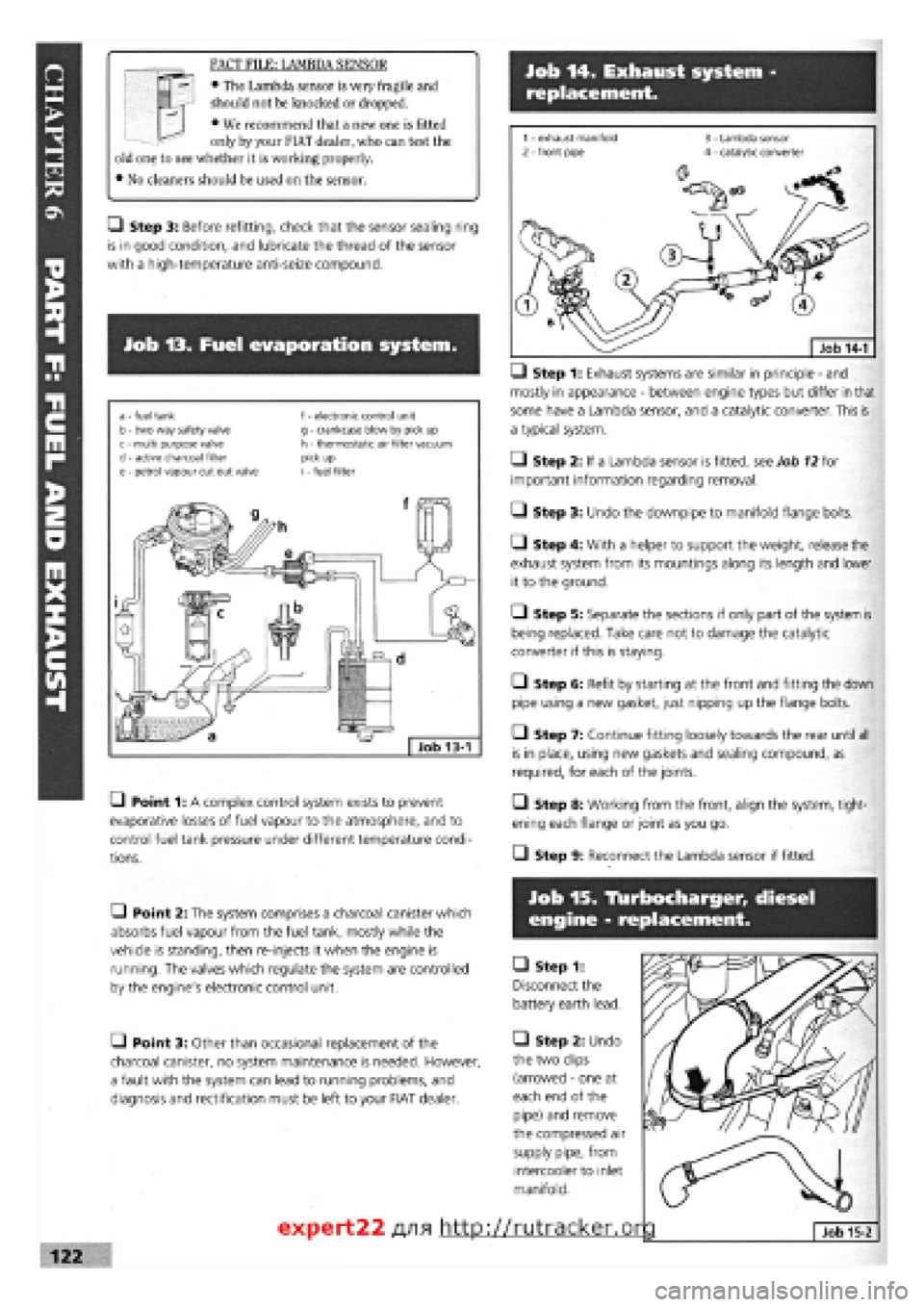
Job 13. Fuel evaporation system.
a - fuel tank b - two way safety valve c - multi purpose valve d
-
active charcoal filter e - petrol vapour cut out valve
f - electronic control unit g - crankcase blow by pick up h - thermostatic air filter vacuum pick up i - fuel filter
• Point 1: A complex control system exists to prevent
evaporative losses of fuel vapour to the atmosphere, and to
control fuel tank pressure under different temperature condi-
tions.
—) Step 1: Exhaust systems are similar in principle
-
and
mostly in appearance
-
between engine types but differ in that
some have a Lambda sensor, and a catalytic converter. This is
a typical system.
• Step 2: If a Lambda sensor is fitted, see Job
12
for
important information regarding removal.
• Step 3: Undo the downpipe to manifold flange bolts.
• Step 4: With a helper to support the weight, release the
exhaust system from its mountings along its length and lower
it to the ground.
O Step 5: Separate the sections if only part of the system is
being replaced. Take care not to damage the catalytic
converter if this is staying.
• Step 6: Refit by starting at the front and fitting the down
pipe using a new gasket, just nipping up the flange bolts.
• Step 7: Continue fitting loosely towards the rear until all
is in place, using new gaskets and sealing compound, as
required, for each of the joints.
• Step 8: Working from the front, align the system, tight-
ening each flange or joint as you go.
• Step 9: Reconnect the Lambda sensor if fitted.
• Point 2: The system comprises a charcoal canister which
absorbs fuel vapour from the fuel tank, mostly while the
vehicle is standing, then re-injects it when the engine is
running. The valves which regulate the system are controlled
by the engine's electronic control unit.
• Point 3: Other than occasional replacement of the
charcoal canister, no system maintenance is needed. However,
a fault with the system can lead to running problems, and
diagnosis and rectification must be left to your FIAT dealer.
Job 15. Tlurbocharger, diesel
engine - replacement.
• Step 1:
Disconnect the
battery earth lead.
• Step 2: Undo
the two clips
(arrowed
-
one at
each end of the
pipe) and remove
the compressed air
supply pipe, from
intercooler to inlet
manifold.
expert22 fl/i* http://rutracker.or
Page 128 of 171
turning while undoing the large nut that secures the top
mounting
-
or ask your FIAT dealer to do it for you. B
• Step 8: Refer to Job
1-1B.
Pull off the mounting (3),
spacer (4), rubber buffer (5), stop buffer and sleeve (6) and the
coil spring (2).
FACT FILE: COIL SPRINGS
If a coil spring is cracked, sagged or heavily
rusted, replace the front springs AS A PAIR.
FIAT springs are colour-coded with a stripe
of either yellow or green paint. Use only a
matching pair.
SAFETY FIRST!
• Never undo the centre nut (Steps 7 and 8) without
using a suitable spring compressor.
• The power contained within the spring is enormous
and extremely dangerous.
• If you are not trained or experienced in this part of
the job, leave it to your FIAT dealer.
Q Step 9: Refit all components in reverse order, making
sure the coil spring is properly seated with the large coil at the
bottom and the end of the coil, tight against the stop in the
spring seat. Tighten to the specified tightening torques (see
Chapter
3,
Facts and Figures) only when the car is back on
its wheels.
Job 12. Front wheel bearing
replacement.
IMPORTANT NOTE: The wheel bearing will probably be
destroyed as it is removed from the hub.
The hub and bearing can
be drifted out from the hub
carrier.
• If you have difficulty doing so, you could remove the
hub carrier and take it to your FIAT dealer for bearing
replacement.
• Step 1: H INSIDE INFORMATION:
• The hub nut (see illustration Job
12-9,
part f) requires
a great deal of torque to undo!
• Lever off the dust cap and slacken the centre hub nut
(see illustration Job 1-1B, part 13) while the car is still
on the ground.
• Try to lift the staking from the groove in the drive-
shaft. If it won't all come clear, don't worry! It will unroll
as the nut is undone.
• You will need an extra-long lever (about half-a-metre
long) to undo the hub nut.
• Slacken the wheel bolts while the car is on the
ground. H
Q Step 2: Raise and support the car on axle stands. Remove
the road wheel. Remove the hub/drive-shaft nut.
• Step 3: Undo the brake caliper and the bracket retaining
bolts. Move the caliper clear, still connected to the hose but
not putting weight on it. See PART H: BRAKES, Job 3.
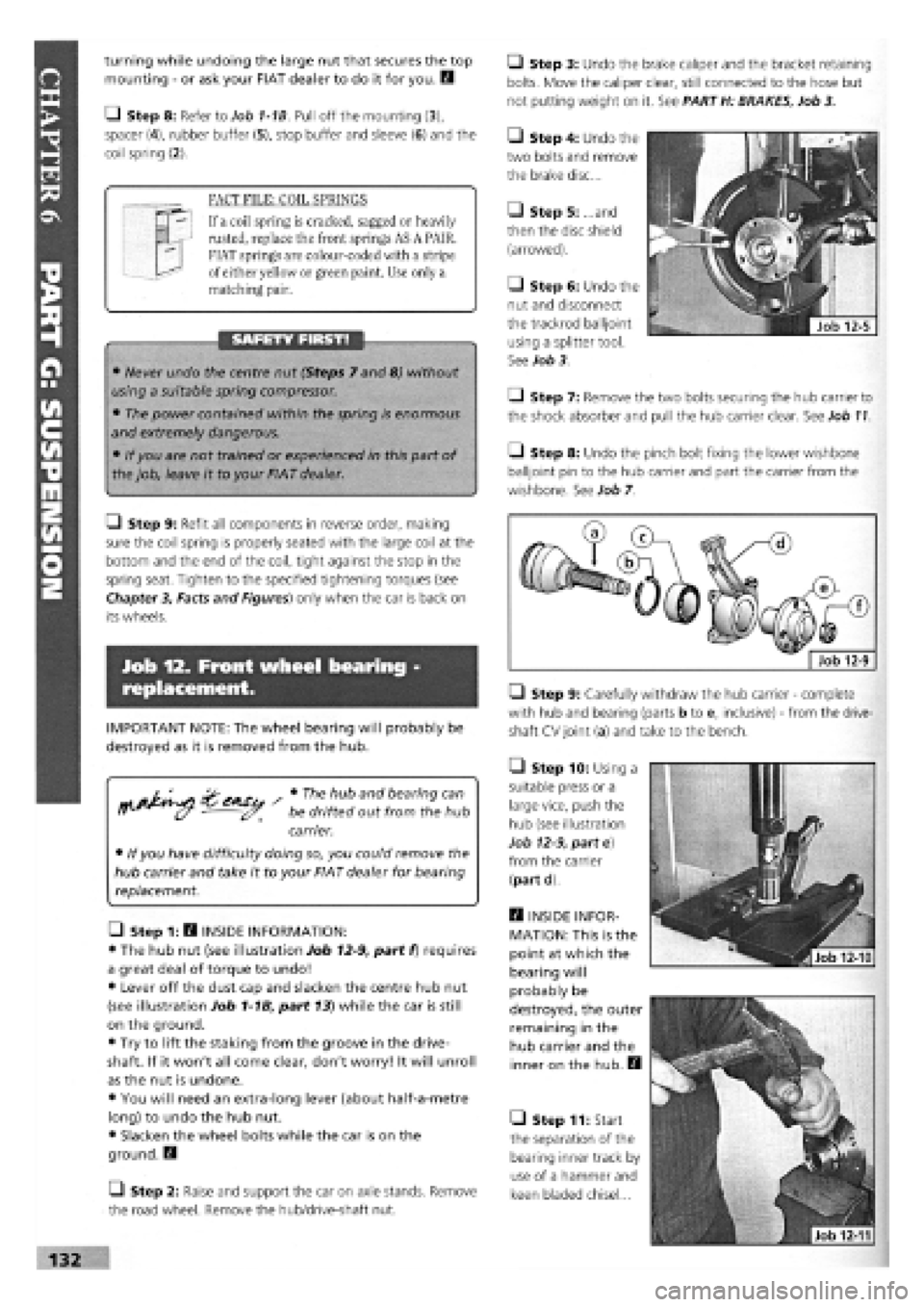
• Step 4: Undo the
two bolts and remove
the brake disc...
• Step 5: ...and
then the disc shield
(arrowed).
• Step 6: Undo the
nut and disconnect
the trackrod balijoint
using a splitter tool.
See Job 3.
Q Step 7: Remove the two bolts securing the hub carrier to
the shock absorber and pull the hub carrier clear. See Job
11.
• Step 8: Undo the pinch bolt fixing the lower wishbone
balijoint pin to the hub carrier and part the carrier from the
wishbone. See Job 7.
• Step 9: Carefully withdraw the hub carrier
-
complete
with hub and bearing (parts b to e, inclusive)
-
from the drive-
shaft CV joint (a) and take to the bench.
Q Step 10: Using a
suitable press or a
large vice, push the
hub (see illustration
Job
12-9,
part e)
from the carrier
(part d)
E3 INSIDE INFOR-
MATION: This is the
point at which the
bearing will
probably be
destroyed, the outer
remaining in the
hub carrier and the
inner on the hub. H
• Step 11: Start
the separation of the
bearing inner track by
use of a hammer and
keen bladed chisel...
Page 129 of 171
Job 13. Rear shock absorbers and
coil springs - replacement.
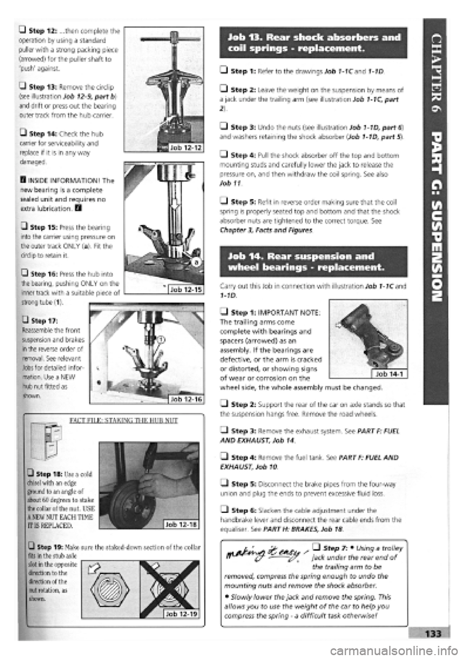
Q Step 12: ...then complete the
operation by using a standard
puller with a strong packing piece
(arrowed) for the puller shaft to
'push' against.
G Step 13: Remove the circlip
(see illustration Job
12-9,
part b)
and drift or press out the bearing
outer track from the hub carrier.
• Step 14: Check the hub
carrier for serviceability and
replace if it is in any way
damaged.
D INSIDE INFORMATION! The
new bearing is a complete
sealed unit and requires no
extra lubrication. D
• Step 15: Press the bearing
into the carrier using pressure on
the outer track ONLY (a). Fit the
circlip to retain it.
• Step 17:
Reassemble the front
suspension and brakes
in
the reverse order of
removal. See relevant
Jobs
for detailed infor-
mation. Use a NEW
hub nut fitted as
shown.
FACT FILE: STAKING THE HUB NUT
• Step 18: Use a cold
chisel
with an edge
ground to an angle of
about 60 degrees to stake
the
collar of the nut. USE
A
NEW NUT EACH TIME
IT IS REPLACED.
Q Step 19: Make sure the staked-down section of the collar
fits
in the stub axle
slot
in the opposite
direction to the
direction of the
nut
rotation, as
shown.
• Step 1: Refer to the drawings Job 1-1Cand 1-1D.
• Step 2: Leave the weight on the suspension by means of
a jack under the trailing arm (see illustration Job
1-1C,
part
• Step 3: Undo the nuts (see illustration Job
1-1D,
part
6)
and washers retaining the shock absorber (Job
1-1D,
part 5).
• Step 4: Pull the shock absorber off the top and bottom
mounting studs and carefully lower the jack to release the
pressure on, and then withdraw the coil spring. See also
Job 11
O Step 5: Refit in reverse order making sure that the coil
spring is properly seated top and bottom and that the shock
absorber nuts are tightened to the correct torque. See
Chapter
3,
Facts and Figures.
Job 14. Rear suspension and
wheel bearings - replacement.
Carry out this Job in connection with illustration Job
1-1C
and
1-1D.
• Step 1: IMPORTANT NOTE:
The trailing arms come
complete with bearings and
spacers (arrowed) as an
assembly. If the bearings are
defective, or the arm is cracked
or distorted, or showing signs
of wear or corrosion on the
wheel side, the whole assembly must be changed.
Q Step 2: Support the rear of the car on axle stands so that
the suspension hangs free. Remove the road wheels.
• Step 3: Remove the exhaust system. See PART F: FUEL
AND EXHAUST, Job 14.
• Step 4: Remove the fuel tank. See PART F: FUEL AND
EXHAUST, Job 10
• Step 5: Disconnect the brake pipes from the four-way
union and plug the ends to prevent excessive fluid loss.
Q Step 6: Slacken the cable adjustment under the
handbrake lever and disconnect the rear cable ends from the
equaliser. See PART H: BRAKES, Job 18
/ • Step 7: • Using a trolley
jack under the rear end of
the trailing arm to be
removed, compress the spring enough to undo the
mounting nuts and remove the shock absorber.
• Slowly lower the jack and remove the spring. This
allows you to use the weight of the car to help you
compress the spring
-
a difficult task otherwise!
Q Step 16: Press the hub into
the bearing, pushing ONLY on the
inner track with a suitable piece of
strong tube (1).
Page 135 of 171

Job 12. Pressure regulating valve,
non-ABS system - replacement
and adjustment.
• Step 9: Bleed the brakes, see Job
17
139
-8
The pressure regulating valve is also known as the load
proportioning valve.
[G Step 1: Position the car on ramps, over a pit or on a lift,
keeping the weight on the rear wheels.
• Step 2: Remove the handbrake cable from its support
bracket on the fuel tank...
• Step 3: ...and
remove the support
bracket for the rear
exhaust section for better
access.
• Step 4: Undo all the
pipe unions on the
regulating valve using
split ring spanners where
possible, to avoid
damage. Plug the ends
of the pipes and catch
any fluid that drains out.
Unhook the spring
(arrowed) from the
mounting bracket.
Q Step 5: Undo the fixing belts and remove the valve
assembly.
• Step 6: Mount the new unit, remake all hydraulic
connections and connect the spring. Note that, if the valve
does not work properly, it cannot be repaired but must be
replaced.
• Step 7: Place a load of 60 kg with a full fuel tank, or 90
kg with an empty fuel tank, as far forward as possible in the
boot.
• Step 4: Prise
off the sound
proofing plate
stud with a screw-
driver (1, which
cannot be re-
used) and
unscrew the stud
(2). Move the
plate (3) to one
side, to give
access to the
servo retaining
nuts.
• Step 5:
Remove the split
pin
and
disconnect the
servo rod from
the brake pedal.
G Step 6: Move
the sound
proofing plate
sufficiently to
remove the servo
mounting nuts
(three
-
arrowed;
one being
unscrewed by a
socket extension).
G Step 7: From
under the bonnet,
withdraw the
servo from the
bulkhead.
G Step 9: Adjust the nut as
necessary to achieve this
setting measuring through
the aperture in the front
cover, from inside the engine
bay.
G Step 10: Continue re-
assembly in reverse order.
G Step 8:
When refitting the
servo to the
bulkhead and
with the pushrod
(a) connected to
the brake pedal,
the gap between
the piston control
rod adjusting nut
(b) and the master
cylinder mounting
flange should be
between 22.45
and 22.65 mm.
22.45-22.65 mm
• Step 8:
• Loosen the
bracket
retaining screw
(1).
• Apply a
downwards
force to the
bracket eye (2)
of 55 Nm for all
models except
the 1600
automatic
petrol and 1900
turbo diesel which should be 30 Nm.
• Keeping the bracket (3) in position. Tighten the retaining
screw (1).
Page 136 of 171
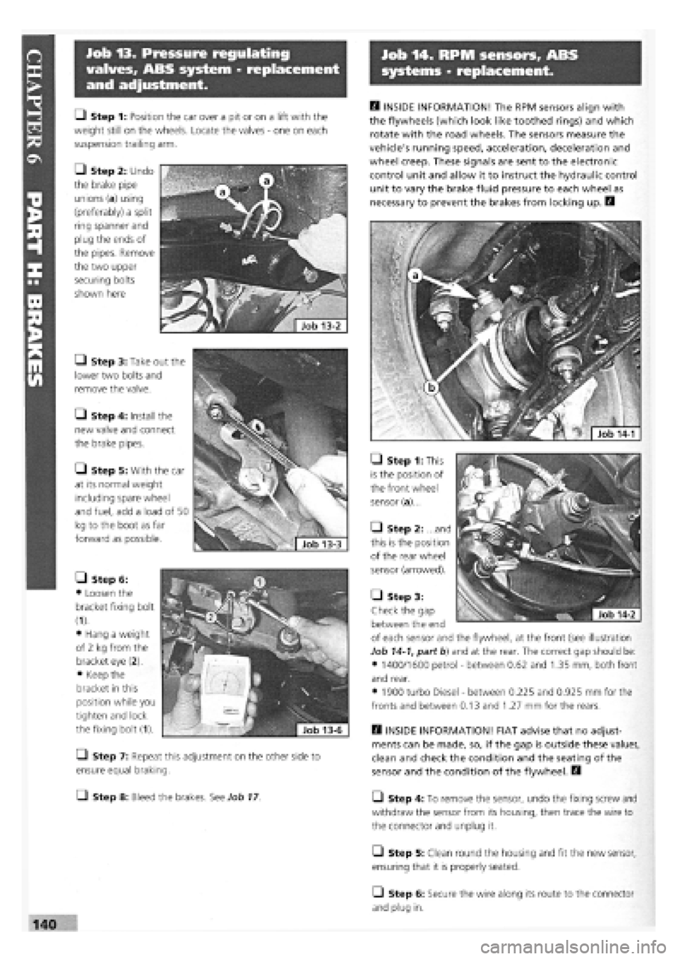
Job 13. Pressure regulating
valves, ABS system - replacement
and adjustment.
Job 14. RPM sensors, ABS
systems - replacement.
H INSIDE INFORMATION! The RPM sensors align with
the flywheels (which look like toothed rings) and which
rotate with the road wheels. The sensors measure the
vehicle's running speed, acceleration, deceleration and
wheel creep. These signals are sent to the electronic
control unit and allow it to instruct the hydraulic control
unit to vary the brake fluid pressure to each wheel as
necessary to prevent the brakes from locking up. E3
• Step 1: This
is the position of
the front wheel
sensor (a)...
• Step 2: ...and
this is the position
of the rear wheel
sensor (arrowed).
H INSIDE INFORMATION! FIAT advise that no adjust-
ments can be made, so, if the gap is outside these values,
clean and check the condition and the seating of the
sensor and the condition of the flywheel. D
L_l Step 4: To remove the sensor, undo the fixing screw and
withdraw the sensor from its housing, then trace the wire to
the connector and unplug it.
• Step 5: Clean round the housing and fit the new sensor,
ensuring that it is properly seated.
O Step 6: Secure the wire along its route to the connector
and plug in.
• Step 1: Position the car over a pit or on a lift with the
weight still on the wheels. Locate the valves
-
one on each
suspension trailing arm.
• Step 2: Undo
the brake pipe
unions (a) using
(preferably) a split
ring spanner and
plug the ends of
the pipes. Remove
the two upper
securing bolts
shown here
• Step 3: Take out the
lower two bolts and
remove the valve.
• Step 4: Install the
new valve and connect
the brake pipes.
• Step 5: With the car
at its normal weight
including spare wheel
and fuel, add a load of 50
kg to the boot as far
forward as possible.
• Step 6:
• Loosen the
bracket fixing bolt
(1).
• Hang a weight
of 2 kg from the
bracket eye (2).
• Keep the
bracket in this
position while you
tighten and lock
the fixing bolt (1).
Q Step 7: Repeat this adjustment on the other side to
ensure equal braking.
• Step 8: Bleed the brakes. See Job
17
• Step 3:
Check the gap
between the end
of each sensor and the flywheel, at the front (see illustration
Job
14-1,
part b) and at the rear. The correct gap should be:
• 1400/1600 petrol
-
between 0.62 and 1.35 mm, both front
and rear.
• 1900 turbo Diesel
-
between 0.225 and 0.925 mm for the
fronts and between 0.13 and 1.27 mm for the rears.