1988 CITROEN CX parking sensors
[x] Cancel search: parking sensorsPage 260 of 648

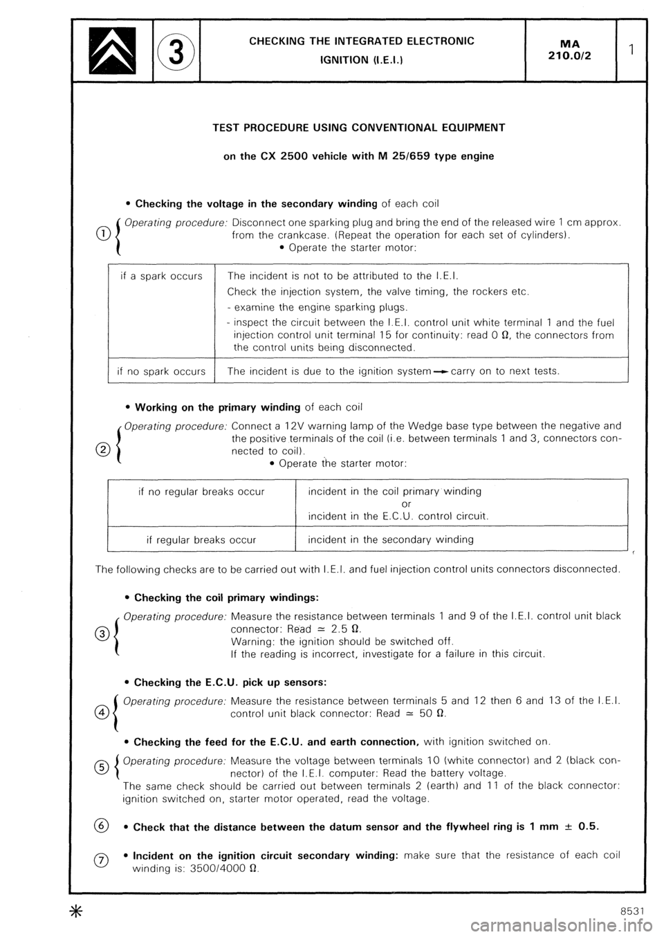
CHECKING THE INTEGRATED ELECTRONlC
IGNITION (I.E.I.)
TEST PROCEDURE USING CONVENTIONAL EQUIPMENT
on the CX 2500 vehicle with M 25/659 type engine
l Checking the voltage in the secondary winding of each coil
0 Operating procedure: Disconnect one sparking plug and bring the end of the released wire 1 cm approx
from the crankcase. (Repeat the operation for each set of cylinders).
l Operate the starter motor:
if a spark occurs The incident is not to be attributed to the I.E.I.
Check the injection system, the valve timing, the rockers etc.
- examine the engine sparking plugs.
- inspect the circuit between the I.E.I. control unit white terminal 1 and the fuel
injection control unit terminal 15 for continuity: read 0 0, the connectors from
the control units being disconnected.
if no spark occurs The incident is due to the ignition system--ccarry on to next tests.
l Working on the primary winding of each coil
Operating procedure: Connect a 12V warning lamp of the Wedge base type between the negative and
0 the positive terminals of the coil (i.e. between terminals 1 and 3, connectors con-
netted to coil).
l Operate the starter motor:
if no regular breaks occur incident in the coil primary winding
or
incident in the E.C.U. control circuit.
if regular breaks occur incident in the secondary winding
The following checks are to be carried out with I.E.I. and fuel injection control units connectors disconnected.
l Checking the coil primary windings:
Operating procedure: Measure the resistance between terminals 1 and 9 of the I.E.I. control unit black
0 connector: Read = 2.5 0.
Warning: the ignition should be switched off.
If the reading is incorrect, investigate for a failure in this circuit.
l Checking the E.C.U. pick up sensors:
co Operating procedure: Measure the resistance between terminals 5 and 12 then 6 and 13 of the I.E.I.
control unit black connector: Read = 50 a.
l Checking the feed for the E.C.U. and earth connection, with ignition switched on
Operating procedure: Measure the voltage between terminals IO (white connector) and 2 (black con-
nector) of the I.E.I. computer: Read the battery voltage.
The same check should be carried out between terminals 2 (earth) and 11 of the black connector:
ignition switched on, starter motor operated, read the voltage.
69 l Check that the distance between the datum sensor and the flywheel ring is 1 mm + 0.5.
0 l Incident on the ignition circuit secondary winding: make sure that the resistance of each coil
winding is: 350014000 a.
8531
Page 261 of 648

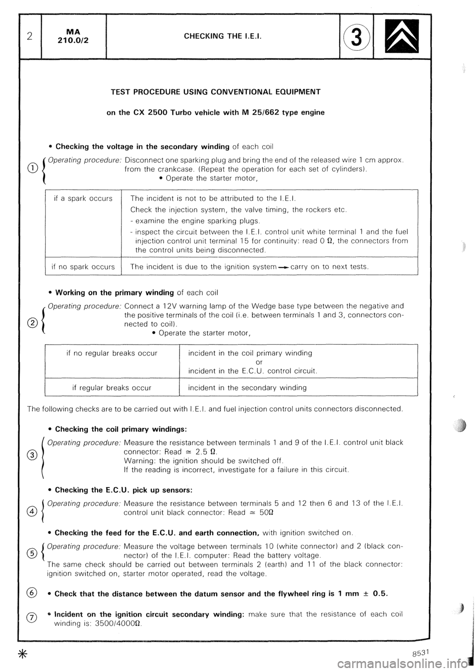
CHECKING THE I.E.I.
TEST PROCEDURE USING CONVENTIONAL EQUIPMENT
on the CX 2500 Turbo vehicle with M 25/662 type engine
0 Checking the voltage in the secondary winding of each coil
0 Operating procedure: Disconnect one sparking plug and bring the end of the released wire 1 cm approx
from the crankcase. (Repeat the operation for each set of cylinders).
0 Operate the starter motor,
if a spark occurs
if no spark occurs The incident is not to be attributed to the I.E.I.
Check the injection system, the valve timing, the rockers etc.
- examine the engine sparking plugs.
- inspect the circuit between the I.E.I. control unit white terminal 1 and the fuel
injection control unit terminal 15 for continuity: read 0 Q, the connectors from
the control units being disconnected.
The incident is due to the ignition system-carry on to next tests.
l Working on the primary winding of each coil
Operating procedure: Connect a 12V warning lamp of the Wedge base type between the negative and
the positive terminals of the coil (i.e. between terminals 1 and 3, connectors con-
netted to coil).
l Operate the starter motor,
if no regular breaks occur incident in the coil primary winding
or
incident in the E.C.U. control circuit.
if regular breaks occur incident in the secondary winding
The following checks are to be carried out with I.E.I. and fuel injection control units connectors disconnected.
0 Checking the coil primary windings:
Operating procedure: Measure the resistance between terminals 1 and 9 of the I.E.I. control unit black
0 connector: Read = 2.5 Q.
Warning: the ignition should be switched off.
If the reading is incorrect, investigate for a failure in this circuit.
l Checking the E.C.U. pick up sensors:
OI Operating procedure: Measure the resistance between terminals 5 and 12 then 6 and 13 of the I.E.I.
4
control unit black connector: Read 2: 5OQ
0 Checking the feed for the E.C.U. and earth connection, with ignition switched on.
d 5 Operating procedure: Measure the voltage between terminals 10 (white connector) and 2 (black con-
nectar) of the I.E.I. computer: Read the battery voltage.
The same check should be carried out between terminals 2 (earth) and 11 of the black connector:
ignition switched on, starter motor operated, read the voltage.
@ 0 Check that the distance between the datum sensor and the flywheel ring is 1 mm + 0.5.
0 * Incident on the ignition circuit secondary winding: make sure that the resistance of each coil
winding is: 350014OOOQ.
Page 265 of 648

CHECKING THE IGNlTlON ADVANCE
of the I.E.I. system
On CX vehicles fitted with I.E.I.
These vehicles having fixed sensors, are not equipped with TDC sensors
I) Marking the TDC:
Draw a mark on the crankcase, in the opening located next to the flywheel pick up sensor
- Remove the 1st or 4th cylinder sparking plug
- Finding the T.D.C. with a locating peg: jack up the vehicle on one side and engage a gear.
Rotate the road wheel in one direction.
Mark down the place where locating pin will enter the flywheel.
Draw a temporary line on the flywheel ring. Rotate the lifted road wheel in the opposite direction, with
the pin still engaged. Mark the position of the pin in the flywheel ring. Take an average of these two marks-
which corresponds to the TDC. Draw a white paint mark on the flywheel ring, opposite the one on the
crankcase.
- Refit the sparking plug.
2) Testing the development of the speedometer advance curve:
- Connect a phase shifting strobe lamp
- Set the strobe lamp to the 2 cyl. u stroke or 1 cyl. 2 stroke position.
- Disconnect the pipe of the load correction depression operated capsule from the inlet manifold. Blank
off the orifice.
- Run the engine and check the advance curve development.
3) Testing the operation of the air-operated capsule on normally aspirated engines:
- Blank off the vacuum capsule venting orifice.
- Connect a vacuum pump to the capsule pipe.
- Run the engine to 2.000 rpm; record the advance reading.
- Create a 400 mbar depression in the vacuum capsule.
The ignition advance increases by about 15’ and the engine accelerates to 200 rpm approx.
On turbocharged engines:
- Connect a vacuum-pressure pump to the capsule pipe.
- Rotate the engine to 200 rpm. Read the advance.
- Build up a 500 mbar depression in the capsule:
- There will be a 22” increase of the ignition advance, approx. and about a 500 rpm engine acceleration.
- Build up a 500 mbar pressure in the capsule:
- There will be a -1 1 o decrease of the ignition advance, approx. and about a 500 rpm engine slowing down
- Pinking: occurs when the engine speed exceeds 1.000 rpm. The warning lamp should light up in the
following cases:
- anti-knock sensor system broken or short-circuited,
- knock sensor broken or short circuited,
- improper earthing provided by the knock sensor.
- Check the operation with the strobe lamp, and a 2.000 rpm engine speed Record the ignition timing.
- Disconnect the knock sensor:
The ignition advance decreases by IO’ approx.