1988 CITROEN CX air filter
[x] Cancel search: air filterPage 157 of 648

GENERAL FEATURES OF THE CARBURATION
FITTING. Fig. I:
5. FIN the tamper-proof protective plug (a):
- load gun A,
- screw tool E onto gun A,
- position plug (a) in its housing on the carburettor (make sure it is fitted the right way round Fig. 111,
- actuate the gun until the plug is properly located.
EXHAUST EMISSION CONTROL
In order to comply with current regulations, the checking and adjustment of the exhaust emission from vehicles
with a petrol engine must, without fail, be performed after the following operations:
I. ENGINE REPLACEMENT.
II. CARBURETTOR REPLACEMENT.
Ill. WORK ON THE CARBURETTOR.
Replacement of parts of the carburettor.
Carburettor adjustment.
Work on the carburettor controls.
IV. WORK ON THE INLET MANIFOLD.
Replacement or removal of:
- the inlet manifold,
- the air filter,
- crankcase gas recirculation system
V. WORK ON THE ENGINE.
Rocker adjustment.
Replacement or removal of:
- the cylinder head,
- the camshaft,
- the rockers,
- the valves,
- the liners and pistons.
VI. WORK ON THE IGNITION.
Replacement or reconditioning of the distributor (wholly or partially)
Adjustment or replacement of the sparking plugs.
Adjustment of the ignition timing.
VII. WORK ON EXHAUST SYSTEM.
Replacement or removal of:
- the exhaust manifold,
- the silencer or any part of the exhaust.
VIII. WORK ON THE EMISSION CONTROL SYSTEM.
When the vehicle is fitted with a specific equipment (e.g. on vehicles of SWEDEN, AUSTRALlA or JAPAN type)
Page 185 of 648

“LE JETRONIC” ELECTRONIC FUEL
INJECTION SYSTEM
“LE Jetronic” system
The “LE Jetronic” IS a fuel injectiorl system which injects Intermittently petrol, at low pressure, into the inlet rnanifold
The main characteristic of the device IS to rneter drrectly the air drawn in by the engine, which is the only reference
for the fuel quantity to be injected. The fuel metering IS carried out by electro-magnetically triggered injectors. These
are under a constant fuel pressure.
The quantrty of fuel injected depends on how long the Injectors remain open. The duration of opening is optimally
determined for each engine operating phase by an electronic control unit, from data supplied by various electric
sensors.
The “LE Jetronic” device is composed of:
No.
COMPONENTS MADE BY REFERENCE
142 Electronic Control Unit (E.C. U.) BOSCH 0280 000 300
192 Throttle spindle switch cc 0280 120 301
280 Supplementary air control (C 0280 140 172
302 Flow meter ,, 0280 202 021
345 Electrovalve ,) 0280 141 011
576 Injector n 0280 150 254
683 Electrical fuel pump
)> 0580 464 008
731 Relay D 0280 230 009
841 Water temperature sensor D 0280 130 026
F Fuel filter N 0450 905 002
R Fuel regulator pressure ,) 0280 160 216
Page 194 of 648

“LE Jetronic” system
The “LE Jetronic” is a fuel injection system whrch injects intermittently petrol, at low pressure, into the Inlet manrfold
The main characteristic of the device is to meter directly the air drawn In by the engine, which is the only reference
for the fuel quantity to be injected. The fuel metering is carried out by electro-magnetically triggered injectors. These
are under a constant fuel pressure.
The quantity of fuel injected depends on how long the injectors remain open. The duration of opening IS optimally
determined for each engine operating phase by an electronic control unit, from data supplied by various electric
sensors.
The “LE Jetronic” device is composed of:
No. COMPONENTS MADE BY REFERENCE
142 Electronic Control Unit (E.C.U.) BOSCH 0280 000 224
192 Throttle spindle switch 0
0280 120 313
280 Supplementary air control u
0280 140 178
302 Flow meter ,)
0280 202 061
345 Electrovalve ,,
0280 141 011
575 Cold start injector n
0280 170 409
576 Injector >,
0280 150 200
683 Electrical fuel
pump 1,
0580 464 008
731 Relay >,
0280 230 009
841 Coolant temperature sensor 1)
0280 130 026
870 Slow thermal switch ,>
0280 130 214
F Fuel filter ),
0450 905 002
R Pressure regulator ,)
0280 160 216
Page 216 of 648

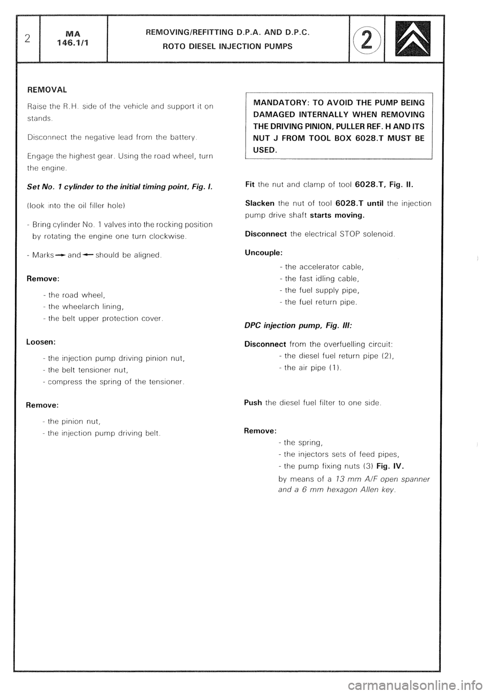
Raise the R.H side of the vehicle and support it on
stands.
Disconnect the negative lead from the battery
Engage the highest gear. Using the road wheel, turn
the engine.
Set No. I cylinder to the initial timing point, Fig. I.
(look into the oil filler hole)
- Bring cylinder No. 1 valves into the rocking position
by rotating the engine one turn clockwise.
- Marks- and- should be aligned.
Remove:
- the road wheel,
- the wheelarch lining,
- the belt upper protection cover.
Loosen:
- the injection pump drrvrng pinion nut,
- the belt tensioner nut,
- compress the spring of the tensioner.
Remove:
- the pinion nut,
- the injection pump driving belt. MANDATORY: TO AVOID THE PUMP BEING
DAMAGED INTERNALLY WHEN REMOVING
THE DRIVING PINION, PULLER REF. H AND ITS
NUT J FROM TOOL BOX 6028.T MUST BE
USED.
Fit the nut and clamp of tool 6028.T, Fig. II.
Slacken the nut of tool 6028.T until the injection
pump drive shaft starts moving.
Disconnect the electrical STOP solenoid
Uncouple:
- the accelerator cable,
- the fast idling cable,
- the fuel supply pipe,
- the fuel return pipe.
DPC injection pump, Fig. ill:
Disconnect from the overfuelling circuit:
- the diesel fuel return pipe (21,
- the air pipe (I 1.
Push the diesel fuel filter to one side
Remove:
- the spring,
- the injectors sets of feed pipes,
- the pump fixing nuts (3) Fig. IV.
by means of a 73 mm A/F open spanner
and a 6 mm hexagon Allen key.
Page 218 of 648

REMOVING/REFITTING D.P.A. AND D.P.C.
ROT0 DIESEL INJECTION PUMPS MA
146.1/l 5
REFITTING
Prepare
- the pump (see Op. @ MA 146.0/l/
Fit
- the pump with the mounting studs in the middle of
the slots,
- the pump fixing nuts but do not tighten home.
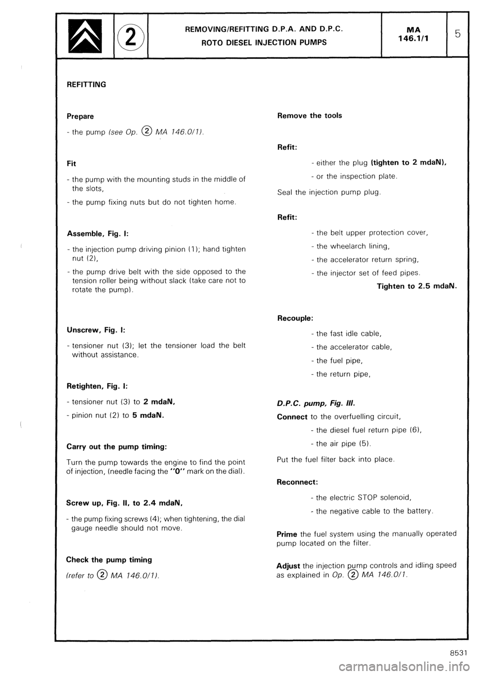
Assemble, Fig. I:
- the injection pump driving pinion t I); hand tighten
nut (2),
- the pump drive belt with the side opposed to the
tension roller being without slack (take care not to
rotate the pump).
Unscrew, Fig. I:
- tensioner nut (3); let the tensioner load the belt
without assistance.
Retighten, Fig. I:
- tensioner nut (3) to 2 mdaN,
- pinion nut (2) to 5 mdaN.
Carry out the pump timing:
Turn the pump towards the engine to find the point
of injection, (needle facing the “0” mark on the dial).
Screw up, Fig. II, to 2.4 mdaN,
- the pump fixing screws (4); when tightening, the dial
gauge needle should not move.
Check the pump timing (refer to @ MA 146.011)
Remove the tools
Refit:
- either the plug (tighten to 2 mdaN),
- or the inspection plate.
Seal the injection pump plug.
Refit:
- the belt upper protection cover,
- the wheelarch lining,
- the accelerator return spring,
- the injector set of feed pipes.
Tighten to 2.5 mdaN.
Recouple:
- the fast idle cable,
- the accelerator cable,
- the fuel pipe,
- the return pipe, D.P.C. pump, Fig. III.
Connect to the overfuelling circuit,
- the diesel fuel return pipe (61,
- the air pipe (5).
Put the fuel filter back into place.
Reconnect:
- the electric STOP solenoid,
- the negative cable to the battery.
Prime the fuel system using the manually operated
pump located on the filter.
Adjust the injection pump controls and idling speed
as explained in Op. @ MA 146.0/l.
8531
Page 222 of 648

SPECIFICATION AND SPECIAL FEATURES
OF THE AIR SUPPLY SYSTEM
Engines types 829.A5 and J6T.A500 are fitted with a device regulating the temperature of intake air.
This device has been designed for maintaining a minimum temperature of the air drawn into the carburettor
It consists of a thermal sensor and a vacuum capsule operating a flap. Thermal source
The thermal sensor is located in the pipe connecting the air filter to the inlet manifold of the carburettor
This bi-metal type thermostat, is subjected to the inlet air temperature
It controls the opening of valves allowing passage for a depression towards the capsule
This depression is picked up by a union having a calibrated orifice, fitted to the pipe connecting the oil breather
to the intake manifold of the carburettor, and by a T-shaped union situated near the carburettor base plate, so
as to have an action over the engine load.
The thermal sensor allows the depression to circulate when the temperature is below 15°C and stops it when the
temperature exceeds 25°C. Vacuum capsule.
The capsule, located in the inlet of the air filter, is subjected to the depression. When energised, it operates a flap
which lets the heated air coming from a tapping located on the exhaust shield enter. At rest, the flap lets intake
air coming from behind the grill enter.
Page 318 of 648

REPAIR OF THE HYDRAULIC SYSTEM
FITTING PRECAUTIONS
PRECAUTIONS TO BE TAKEN WHEN WORKING ON
THE HYDRAULIC UNITS OR THE SYSTEM
The correct functioning of the entire system presupposes perfect cleanliness of the fluid and the hydraulic
units. Stringent precaut!ons must therefore be taken when working on the hydraulic system and during the
storage of the fluid and components. 1. HYDRAULIC FLUID:
Mineral hydraulic fluid (LHM) is the only suitable type and must be used to the exclusion of all others in the hydrau-
lic system of the car.
This LHM fluid is green in co/our and similar to engine oil.
The use of any other would ruin the rubber rings and seals in the system. 2. RUBBER UNITS AND PARTS:
Suitable components are identified by their green co/our and may only be replaced by genuine replacement
components painted or marked in green.
All rubber components (seals, hoses, diaphragm, etc...) are of a special quality for use with LHM fluid and are
identified by their white or green colour. 3. STORAGE:
Components must be stored, full of fluid and blanked off. Like the piping, they must be protected against shock
and the ingress of dust.
Rubber tubing and joints must be stored away from dust, air, light and heat.
LHM hydraulic fluid must be stored in its original containers carefully sealed. We advise the use of one litre (for
topping up) or five litre cans (for refilling) to avoid having to keep opened containers. 4. CHECKS BEFORE CARRYING OUT WORK:
Before-working on the hydraulic system in case of faulty operation, ensure the following:
a) That the controls or the mechanical linkages of the units or the group of hydraulic units involved are
not stiff in operation
I I
b) and that the HP circuit is under pressure, as follows:
With the engine at idling speed:
- Unscrew the pressure-release screw on the pressure regulator by one turn to one turn and a half: a sound
of leakage should be heard from the regulator.
- Retighten the release screw: cut-out must occur which results in a reduction in the running noise emitted
by the H.P. pump.
If not, check in the following sequence:
- that there is sufficient fluid in the reservoir,
- that the reservoir filter is clean and in good condition,
- that the H.P. pump is primed and there is no air leak on the suction side of the pump,
- that the release screw of the pressure regulator is correctly tightened,
- that sealing ball (2) is in position, (see Fig. I and II, page 5).