1988 CITROEN CX Earth
[x] Cancel search: EarthPage 17 of 648

PROTECTION OF THE ELECTRICAL COMPONENTS
PRECAUTIONS TO BE TAKEN WHEN CARRYING OUT AN OPERATION ON THE VEHICLE
It is essential to avoid actrons which may damage the electrical or the electronic equipment or create a short circuit
(wrth subsequent risk of fire or accident).
Battery:
a) First disconnect cable clamp from the battery negative terminal, earthed, then from the positive post.
b 1 Before tightening the negative clamp to the battery (the negative lead should be connected last), ensure that there
is no short circuit (bright sparks or arcs).
Small sparks may occur due to the interior lamp (door open), door locking device, clock or components having
remained in operation.
c 1 Make sure that the terminals are properly connected. Clamps and terminals should be clean and correctly tightened.
d ) When recharging the battery, disconnect the two clamps first.
e) Do not reverse the negative and positive clamps on the battery. (This could destroy the alternator diodes).
Fuses:
a 1 Fit the correct type of fuses: use the fuses specified for the protected devices
b 1 Take the added accessories and the functions into consideration.
Charging circuit:
,a 1 Do not run the alternator unless it is connected to the battery. Do not disconnect the battery when the alternator
is rotating.
b 1 Ensure that the regulator is correctly earthed.
c ) Do not interchange the leads connected to the regulator, (charge detection warning lamp and excitation are specific).
d ) Do not connect a suppressor capacitor to the regulator without taking precautions or following proper
instructions.
e 1 Do not use an electric welding equipment on the vehicle without having first disconnected the alternator, the regula-
tor and the battery (insulate the two terminals).
f 1 Do not R check )) the operation of an alternator by short circuiting the positive and ground terminals, which may
destroy the diodes.
Starting the engine:
Do not use a booster or a 24-volt battery. Only use a correctly charged 12-volt battery (a higher capacity battery may
be utilised). Otherwise, risk of deterioration of the ignition module or any other electronic control units. If the starter
is needed for starting the engine, without running it, it is necessary to disconnect datum and flywheel sensors on the
All Electronic Ignition, or the primary lead of the coil on any other type of ignition.
Ignition:
a 1 Do not connect a suppressor capacitor to the negative terminal of the coil.
b 1 Do not operate the module if its radiator is not connected to the earth.
c 1 Fit the radio suppressor capacitors recommended by the factory.
d 1 Never operate the ignition system while the HT circuit is open. Connect the HT leads to earth
e) Only use rev. counter having a HT sensor, (never puncture HT leads).
0.1. bulb:
a) Never replace a 01. bulb with the headlamp switched on. If the headlamps have been in use, allow them to cool down.
b) Do not touch a 0.1. bulb with bare fingers. Any fingerprints must be cleaned with soapy water and the bulb dried
with a dry lint-free cloth.
Checks :
a) Preferably use a high resistance (> 10 k Q VI voltmeter or a battery-operated ohm-meter
b) Take care not to use instruments taking their power from the mains.
Electronic components:
a) Avoid overvoltages due to a badly insulated charger, electric arcing or connections to the coil.
The units such as regulator, ignition module, tachometer, windscreen wiper timer, flasher unit, clock, radio, oil gauge
unit, door lock control unit, etc. comprising electronic components may be deteriorated.
b) The electronic components should not be placed or operated under a temperature exceeding 80°C.
c) Always switch off instruments or electronic control units before connecting or disconnecting them.
‘
Page 233 of 648
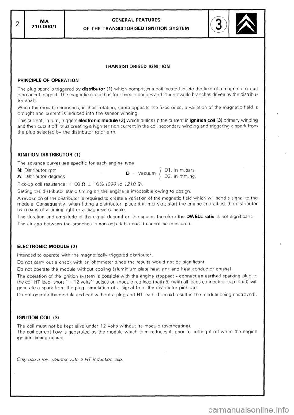
GENERAL FEATURES
OF THE TRANSISTORISED IGNITION SYSTEM
TRANSISTORISED IGNITION
PRINCIPLE OF OPERATION
The plug spark is triggered by distributor (1) which comprises a coil located inside the field of a magnetic circuit
permanent magnet. The magnetic circuit has four fixed branches and four movable branches driven by the distribu-
tor shaft.
When the movable branches, in their rotation, come opposite the fixed ones, a variation of the magnetic field is
brought and current is induced into the sensor winding.
This current, in turn, triggers electronic module (2)
which builds up the current in ignition coil (3) primary winding
and then cuts it off, thus creating a high tension current in the coil secondary winding and triggering a spark from
the plug selected by the distributor rotor arm. IGNITION DISTRIBUTOR (I!
The advance curves are specific for each engine type
N: Distributor rpm
D = Vacuum Dl, in m.bars A:
Distributor degrees 02, in mm.hg
Pick-up coil resistance: 1100 Q sr 10% (990 to 1210 02)
Setting the distributor static timing on the engine is impossible owing to design.
A revolution of the distributor is required to create a variation of the magnetic field which will send a signal to the
module. Consequently, when fitting a distributor, place it in mid-slot; start the engine and adjust the distributor
by means of a timing light or a diagnosis console.
The duration and amplitude of the signal depend on the speed, therefore the DWELL ratio
is not significant.
The air gap between the branches is non-adjustable and it cannot be measured ELECTRONIC MODULE (2)
Intended to operate with the magnetically-triggered distributor.
Do not carry out a check with an ohmmeter since the results would not be significant.
Do not operate the module without cooling (aluminium plate heat sink and heat conductor grease).
The operation of the ignition system is possible with the engine stopped: - connect an earthed sparking plug to
the coil HT lead; short ” + 12 volts” pulses on module red lead (path 5) (with all leads connected, cap lifted) will
generate a spark from the plug: simulation of a signal from the distributor pick up).
Do not operate the module and coil without a plug and HT lead, (It could result in the module being destroyed). IGNITION COIL (3)
The coil must not be kept alive under 12 volts without its module (overheating).
The coil current flow is generated by the module which then reduces it, prior to cutting it off when the engine
ignition timing occurs.
Only use a rev. counter with a UT induction clip.
Page 256 of 648

CHECKlNG THE TRANSISTORISED IGNITION
ELECTRO-MAGNETICALLY TRIGGERED TRANSISTORISED IGNITION
PRELIMINARY CHECKS:
Inspect:
- the connection of the different leads (in particular to coil: a bad connection can cause a high voltage drop preven-
ting the current from passing into the coil primary winding (I 5 A approx),
- condition of the leads : (circuits broken, short-circuits across screening, etc.),
- condition of the sparking plugs (deposits, cracks due to overtightening),
- condition of the distributor cap (wear, cracks) and the rotor arm (loose).
Disconnect the interference suppression capacitor and the diagnosis harness, from the circuit.
Carry out a ((spark test)) with the starter motor and one plug earthed.
IMPORTANT: The module may be destroyed if one of the secondary wires is too far from the earth. CHECKING THE COIL (3) (ignition module and supply to coil disconnected):
MEASUREMENT OF Ohmmeter placed between channels No. Reading (in 0)
Primary winding resistance 1 and 4 DUCELLIER 0.76 to 0.84
BOSCH 0.74 to 0.90
Secondary coil resistance 1 4 and HT coil contact DUCELLIER 5700 to 6300
or
BOSCH 7425 to 9075
Insulation 1 or 4 and earth 00
Checking the coil power supply using a lamp or a voltmeter:
- Switch on the ignition: there should be a 12V current between the “BAT” terminal of the coil and the earth
- Switch off ignition. CHECKING THE IGNITION MODULE (2):
The module is designed to function with the ignition distributor and the coil.
- Do not operate the module without cooling (aluminium plate heat sink) or ventilation
- Do not check the module with an ohmmeter since the results will be non-significant.
Checking the module power supply using a lamp or a voltmeter:
- Disconnect the module connector
- Switch on the ignition: there should be a 12 V current between the channel 4 of the connector and the earth.
- Switch off ignition.
The low voltage ignition circuit being connected (in working order), disconnect the coil - distributor HT lead on
the distributor side and connect it up to an earthed plug: by sending short pulses ( + 12 VI to channel 5 (red wire)
from the module, sparks should occur at the plug (simulation of distributor spark current). CHECKING THE IGNITION DISTRIBUTOR (1):
Test the impulse generator with the module connector disconnected. MEASUREMENT OF:
Resistance
Earth
Insulation Ohmmeter placed between channels No. 5 and 6
2 and engine earth
5 and 2 then 5 and 3 Readings (in Q) 950 to 1250 approx.
0
m
,
Page 260 of 648
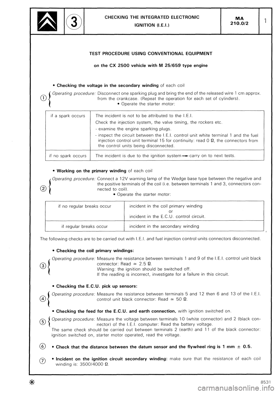
CHECKING THE INTEGRATED ELECTRONlC
IGNITION (I.E.I.)
TEST PROCEDURE USING CONVENTIONAL EQUIPMENT
on the CX 2500 vehicle with M 25/659 type engine
l Checking the voltage in the secondary winding of each coil
0 Operating procedure: Disconnect one sparking plug and bring the end of the released wire 1 cm approx
from the crankcase. (Repeat the operation for each set of cylinders).
l Operate the starter motor:
if a spark occurs The incident is not to be attributed to the I.E.I.
Check the injection system, the valve timing, the rockers etc.
- examine the engine sparking plugs.
- inspect the circuit between the I.E.I. control unit white terminal 1 and the fuel
injection control unit terminal 15 for continuity: read 0 0, the connectors from
the control units being disconnected.
if no spark occurs The incident is due to the ignition system--ccarry on to next tests.
l Working on the primary winding of each coil
Operating procedure: Connect a 12V warning lamp of the Wedge base type between the negative and
0 the positive terminals of the coil (i.e. between terminals 1 and 3, connectors con-
netted to coil).
l Operate the starter motor:
if no regular breaks occur incident in the coil primary winding
or
incident in the E.C.U. control circuit.
if regular breaks occur incident in the secondary winding
The following checks are to be carried out with I.E.I. and fuel injection control units connectors disconnected.
l Checking the coil primary windings:
Operating procedure: Measure the resistance between terminals 1 and 9 of the I.E.I. control unit black
0 connector: Read = 2.5 0.
Warning: the ignition should be switched off.
If the reading is incorrect, investigate for a failure in this circuit.
l Checking the E.C.U. pick up sensors:
co Operating procedure: Measure the resistance between terminals 5 and 12 then 6 and 13 of the I.E.I.
control unit black connector: Read = 50 a.
l Checking the feed for the E.C.U. and earth connection, with ignition switched on
Operating procedure: Measure the voltage between terminals IO (white connector) and 2 (black con-
nector) of the I.E.I. computer: Read the battery voltage.
The same check should be carried out between terminals 2 (earth) and 11 of the black connector:
ignition switched on, starter motor operated, read the voltage.
69 l Check that the distance between the datum sensor and the flywheel ring is 1 mm + 0.5.
0 l Incident on the ignition circuit secondary winding: make sure that the resistance of each coil
winding is: 350014000 a.
8531
Page 261 of 648
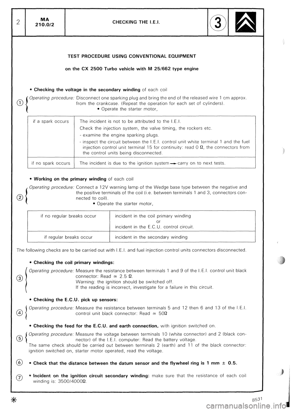
CHECKING THE I.E.I.
TEST PROCEDURE USING CONVENTIONAL EQUIPMENT
on the CX 2500 Turbo vehicle with M 25/662 type engine
0 Checking the voltage in the secondary winding of each coil
0 Operating procedure: Disconnect one sparking plug and bring the end of the released wire 1 cm approx
from the crankcase. (Repeat the operation for each set of cylinders).
0 Operate the starter motor,
if a spark occurs
if no spark occurs The incident is not to be attributed to the I.E.I.
Check the injection system, the valve timing, the rockers etc.
- examine the engine sparking plugs.
- inspect the circuit between the I.E.I. control unit white terminal 1 and the fuel
injection control unit terminal 15 for continuity: read 0 Q, the connectors from
the control units being disconnected.
The incident is due to the ignition system-carry on to next tests.
l Working on the primary winding of each coil
Operating procedure: Connect a 12V warning lamp of the Wedge base type between the negative and
the positive terminals of the coil (i.e. between terminals 1 and 3, connectors con-
netted to coil).
l Operate the starter motor,
if no regular breaks occur incident in the coil primary winding
or
incident in the E.C.U. control circuit.
if regular breaks occur incident in the secondary winding
The following checks are to be carried out with I.E.I. and fuel injection control units connectors disconnected.
0 Checking the coil primary windings:
Operating procedure: Measure the resistance between terminals 1 and 9 of the I.E.I. control unit black
0 connector: Read = 2.5 Q.
Warning: the ignition should be switched off.
If the reading is incorrect, investigate for a failure in this circuit.
l Checking the E.C.U. pick up sensors:
OI Operating procedure: Measure the resistance between terminals 5 and 12 then 6 and 13 of the I.E.I.
4
control unit black connector: Read 2: 5OQ
0 Checking the feed for the E.C.U. and earth connection, with ignition switched on.
d 5 Operating procedure: Measure the voltage between terminals 10 (white connector) and 2 (black con-
nectar) of the I.E.I. computer: Read the battery voltage.
The same check should be carried out between terminals 2 (earth) and 11 of the black connector:
ignition switched on, starter motor operated, read the voltage.
@ 0 Check that the distance between the datum sensor and the flywheel ring is 1 mm + 0.5.
0 * Incident on the ignition circuit secondary winding: make sure that the resistance of each coil
winding is: 350014OOOQ.
Page 265 of 648

CHECKING THE IGNlTlON ADVANCE
of the I.E.I. system
On CX vehicles fitted with I.E.I.
These vehicles having fixed sensors, are not equipped with TDC sensors
I) Marking the TDC:
Draw a mark on the crankcase, in the opening located next to the flywheel pick up sensor
- Remove the 1st or 4th cylinder sparking plug
- Finding the T.D.C. with a locating peg: jack up the vehicle on one side and engage a gear.
Rotate the road wheel in one direction.
Mark down the place where locating pin will enter the flywheel.
Draw a temporary line on the flywheel ring. Rotate the lifted road wheel in the opposite direction, with
the pin still engaged. Mark the position of the pin in the flywheel ring. Take an average of these two marks-
which corresponds to the TDC. Draw a white paint mark on the flywheel ring, opposite the one on the
crankcase.
- Refit the sparking plug.
2) Testing the development of the speedometer advance curve:
- Connect a phase shifting strobe lamp
- Set the strobe lamp to the 2 cyl. u stroke or 1 cyl. 2 stroke position.
- Disconnect the pipe of the load correction depression operated capsule from the inlet manifold. Blank
off the orifice.
- Run the engine and check the advance curve development.
3) Testing the operation of the air-operated capsule on normally aspirated engines:
- Blank off the vacuum capsule venting orifice.
- Connect a vacuum pump to the capsule pipe.
- Run the engine to 2.000 rpm; record the advance reading.
- Create a 400 mbar depression in the vacuum capsule.
The ignition advance increases by about 15’ and the engine accelerates to 200 rpm approx.
On turbocharged engines:
- Connect a vacuum-pressure pump to the capsule pipe.
- Rotate the engine to 200 rpm. Read the advance.
- Build up a 500 mbar depression in the capsule:
- There will be a 22” increase of the ignition advance, approx. and about a 500 rpm engine acceleration.
- Build up a 500 mbar pressure in the capsule:
- There will be a -1 1 o decrease of the ignition advance, approx. and about a 500 rpm engine slowing down
- Pinking: occurs when the engine speed exceeds 1.000 rpm. The warning lamp should light up in the
following cases:
- anti-knock sensor system broken or short-circuited,
- knock sensor broken or short circuited,
- improper earthing provided by the knock sensor.
- Check the operation with the strobe lamp, and a 2.000 rpm engine speed Record the ignition timing.
- Disconnect the knock sensor:
The ignition advance decreases by IO’ approx.
Page 311 of 648

REMOVING AND REFITTING A SWIVEL
REFITTING Replace, Fig. IV:
Wipe the ball-joint fixings and location, do not use - flexible pipe (I I) into its fixing bracket,
solvent. - washer (I 0).
Recouple the upper ball-joint with the swivel. Tighten nut (9) to 2.2 mdaN.
Refit, Fig. I: Recouple:
- washer (I),
- Fig. IV, connection (I 2) provided with a new sea/.
- nut (2).
- Fig. V, the steering ball-joint.
Tighten to 7 mdaN (New NYLSTOP nut).
Refit:
Introduce the drive-shaft end into the wheel hub - washer (I 31,
(lubricate the hub seal lips). - nut (14) (New NYLSTOP one).
Couple up the lower ball-joint. Tighten to 6 mdaN.
Tighten to 6 mdaN the new NYLSTOP nut. Reconnect:
-cup (171,
Reconnect the brake pad wear warning lamp harness. - spring (I 61,
-cable (15).
Refit, Fig. II and Ill:
Adjust the handbrake (as indicated in @ 454.011).
- electrical harness fixing bracket (4).
- earth lead (5).
- screw (3). Put the drive-shaft nut into place.
- metal panel (6). (Faces and threads lubricated).
Lock the hub, utilizing tool 6310-T Fig. VI.
ABS vehicles, Fig. Ill:
Tighten to 37.5 mdaN.
Reinstall sensor (7) (spread MOB/L TEMP No. 1
grease over the outside of the sensor.
Bleed the front brakes (see @ 453.0/l/.
Tighten screw (8) to 1 mdaN.
Fit the wheel.
Lower the vehicle to the ground.
8531-8532
Page 378 of 648

ELECTRICITY
MA 510.00011 1
ELECTRICAL INSTALLATION GENERAL OUTLINES
PRESENTATION:
The electrical system operations are composed of:
- A main wiring diagram.
- A circuit diagram.
- Lists of parts,
harnesses,
earth connections,
connectors between harnesses.
- A fuse table.
A lamp chart.
- Various circuit and wiring diagrams for special functions or optional equipment.
I_
UTILISATION:
The wiring diagram indicates the location of the components, harnesses, earth connections and connectors
on the vehicle.
The circuit diagram presents the electrical circuits in a functional way.
- The components symbols in the circuit diagra*m are those shown on the symbol key (see pages 2 and 31.
- Several symbols can be used for a component and the item can be shownC.exploded on different lines
according to the functions.
- Switches are shown at rest, with vehicle stationary, and the doors closed.
- The switches must be moved from right to left.
- The position of a relay coil, generally to the left of the contact switch, is not compulsorily so.
- In cases where the selector switch is complex, the contact movements are shown in the manner to be
considered the most comprehensible.
- The electronic control units are not shown in detail.
Parts list: the parts are in the alphabetical order, and numbered.
The number of the item remains the same on all the diagrams provided the functron has not changed. The
parts list enables any item to be located on the wiring diagram (by means of letters and figures), and on the
circuit diagram (with a vertical line No). The identification of the connector and the ref. letter of the harness
attached to the part are also included in the parts list.
List of harnesses: it gives the position of electrical harnesses on the wiring diagram and the location of each
lead of this harness on the circuit diagram (capital letter in the middle of the wire).
List of earth connections: it indicates the location of the earth connections and the wires or connectors and
the connecting harnesses (letter CC m )), followed by a number).
List of harness inter connections : it indicates,
- the reference of the harness concerned,
- the type of end fittings: I, metal contact or connecting pin,
U, clip or socket,
- the colour of the wire insulator and the marking or sleeve colour code,
- the junction connector: number of channels, colour and channel involved,
- the location of this connector on the wiring diagram,
- the location of each channel of the connector on the circuit diagram.
The harnesses are described in alphabetic order.
8531 8532