1987 PORSCHE 944 fuel filter
[x] Cancel search: fuel filterPage 3 of 66

INDEX
A
ABS Acceleration diagram Accelerator pedal Air Bag System Air - cleaner
- conditioner
- filter
Alternator warning light Antifreeze Antilock, Brake system Anti-theft alarm Ashtray Automatic- garage door
- speed control
- transmission
- transmission fluid B
Battery
Boost pressure gauge
Brake - booster
- fluid
- fluid warning light
- pads
- parking
- pedal
- system
- warning light
Break-in hints
Bulb replacing
Buzzer 28,39
118-129
55
20, 21, 38, 3980, 8144-4680,81 39
74,75,11028, 39
11
42, 98
25
29
53-55
78,110,128
90-9234
27
39,79,11039
27,37,47,79,80 26
26, 27
26,27,11537
47
93-98
10,18,24,30
C/D
CASIS
Capacities
Car care instructions
Casis
Catalytic Converter
Cautions
Central locking
Central warning light
Cigarette lighter
Cleaning
Clock
Clutch pedal
Collapsible spare tire
Control warning light system
Coolant Temperature Gauge
Cooling system
Corrosion prevention
Dashboard
Defogging/defrosting
Dimensions
Doors
Driving hints
E/F
Electrical system
Emergency- flasher
- starting
Emission Control System
Engine - cooling
- exhaust
- hood
- number
- oil checking & changing
- oil
-speed, max 35
110
61-66
35
50,10267
13
37
41
61-66 40
27
85
36-39 36
74-77
65-66
24
44-46 114
12,138-9, 48, 49
89-92
41
92
100-103 74-77
48
586
69-72
69,110,111,128
34,47,52,106-
108
Fan control switch knob
Fan, radiator
Filling capacities
Fog lights
Fuel - economy
- evaporation control
- gauge
- recommendation
- tank
Fuses and relays
G/H
Gas Station Information
Gasohol
Gasoline
Gear ratio diagram
Gearshift lever
Glove compartment
Hatchback
Headlights
Headlight- dimmer
- flasher
- switch
- washing system
Heater/ventilation controls
Hood - front
- rear
Horn
I/J
Ignition/steering lock
Instrument illumination
Instruments
Interior ligh 44
36, 74 110
30, 96, 97
49
103 37
50, 51
50,110
89,126
126-129 51
50,51
122-125 52-55
42
56
30,95,99 30
30
30
31,32,81,11044-4658
56,57
21,24
24
30
33-40
43, 98
4
Jack
- supports
K/L
Keys
Kickdown
Lane changer
Leather
License plate light
Light switch
Lights - ashtray
- fog
- interior
- license plate
- parking
- turn signal
Locks - doors, wheels
Loudspeakers
Lubricants
Luggage compartment
M/O
Manual transmission
- oil
Mirrors
Oil- change
- consumption
- filter changing
- pressure gauge
- pressure warning light
Octane rating
Oxygen Sensor
P/R
Paint code number 68
87, 88, 129
10-11,86 55
30
65
98
30
98
30, 96, 97
43, 9898
30, 37, 93, 94
30,93,94
10-13, 86 89
110,111 57
52,122-125 77,11022,43
71,72
47, 69
71, 72 38
38
50, 51,106-108 101,102
7
Parking- brake
- lights
Performance
Power assisted steering
Power train
Power windows
Prop-up roof
Radiator fan
Rear - hood
- view mirrors
- window defogger
- wiper
Recirculation Switch
Refrigerant
Relays
Rims
Roof racks
Roof, removable S
Safe driving hints
Safetybelts
Safety belt warning light
Safety compliance sticker
Seat heating System
Seats
Sekuriflex windshield
Shift indicator
Shift points
Side marker lights
Ski racks
Snow- chains
- tires
Spare tire, collapsible
Spark plugs
Specifications, engine
26, 3730,37,93,94116731091259, 6036, 7456,572241424446,11089,12664,112,11357,11459, 60
8-9
17-21,6518,3771514-1631, 63, 643552-559457,11483, 84,112,113
83,84, 111,113
85106-108106-109
Speedometer
Starting procedures
Sun visors
T/U
Tachometer
Technical data
Tirepressure
Tires
Tool kit
Trip odometer
Transmission oil
Trunk
Turn signal lights
Undercoating
Unleaded fuel
V/W
Vehicle identification
Ventilation
Voltmeter
Warning/indicator lights
Washer reservoir
Washing
Water temperature gauge
Weatherstrips
Weights
Wheel alignment
Wheel nuts, lockable
Wheels
Wheel changing
Windows
Windshield- washer reservoir
- wiper/washer lever 3324, 2543
34, 35105-12582,112,113,12947,82-87,112,113683377, 78,11056,5730, 37, 93, 9465, 66,10050, 51,106-108,110
6-744-463835-4081,11061-6636641141158647,64,82-87,11285-8812,63,6481,11031
5
Page 52 of 66

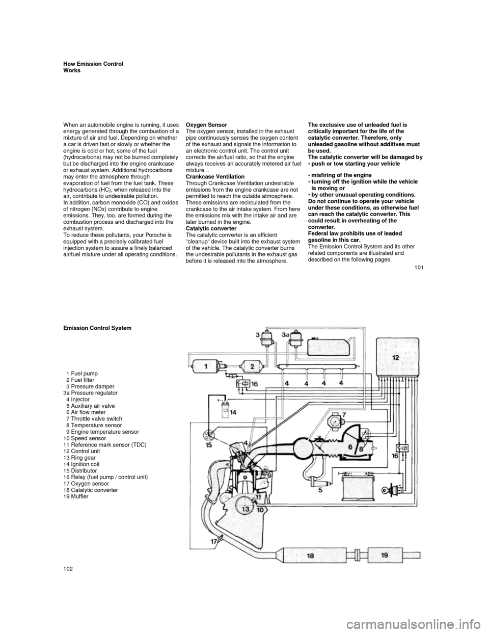
How Emission Control Works
When an automobile engine is running, it uses energy generated through the combustion of a mixture of air and fuel. Depending on whether
a car is driven fast or slowly or whether the
engine is cold or hot, some of the fuel
(hydrocarbons) may not be burned completely but be discharged into the engine crankcase
or exhaust system. Additional hydrocarbons
may enter the atmosphere through
evaporation of fuel from the fuel tank. These
hydrocarbons (HC), when released into the
air, contribute to undesirable pollution.
In addition, carbon monoxide (CO) and oxides of nitrogen (NOx) contribute to engine
emissions. They, too, are formed during the
combustion process and discharged into the
exhaust system.
To reduce these pollutants, your Porsche is
equipped with a precisely calibrated fuel
injection system to assure a finely balanced
air/fuel mixture under all operating conditions.
Oxygen Sensor
The oxygen sensor, installed in the exhaust
pipe continuously senses the oxygen content
of the exhaust and signals the information to
an electronic control unit. The control unit
corrects the air/fuel ratio, so that the engine
always receives an accurately metered air fuel mixture. .
Crankcase Ventilation
Through Crankcase Ventilation undesirable
emissions from the engine crankcase are not
permitted to reach the outside atmosphere.
These emissions are recirculated from the
crankcase to the air intake system. From here
the emissions mix with the intake air and are
later burned in the engine.
Catalytic converter
The catalytic converter is an efficient
"cleanup" device built into the exhaust system
of the vehicle. The catalytic converter burns
the undesirable pollutants in the exhaust gas
before it is released into the atmosphere.
The exclusive use of unleaded fuel is critically important for the life of the
catalytic converter. Therefore, only
unleaded gasoline without additives must
be used.
The catalytic converter will be damaged by
push or tow starting your vehicle
misfiring of the engine turning off the ignition while the vehicle is moving or
by other unusual operating conditions.
Do not continue to operate your vehicle
under these conditions, as otherwise fuel
can reach the catalytic converter. This
could result in overheating of the
converter.
Federal law prohibits use of leaded
gasoline in this car.
The Emission Control System and its other
related components are illustrated and
described on the following pages.
101
Emission Control System
1 Fuel pump
2 Fuel filter
3 Pressure damper
3a Pressure regulator
4 Injector
5 Auxiliary air valve
6 Air flow meter
7 Throttle valve switch
8 Temperature sensor
9 Engine temperature sensor
10 Speed sensor
11 Reference mark sensor (TDC)
12 Control unit
13 Ring gear
14 Ignition coil
15 Distributor
16 Relay (fuel pump / control unit)
17 Oxygen sensor
18 Catalytic converter
19 Muffler
102
Page 53 of 66

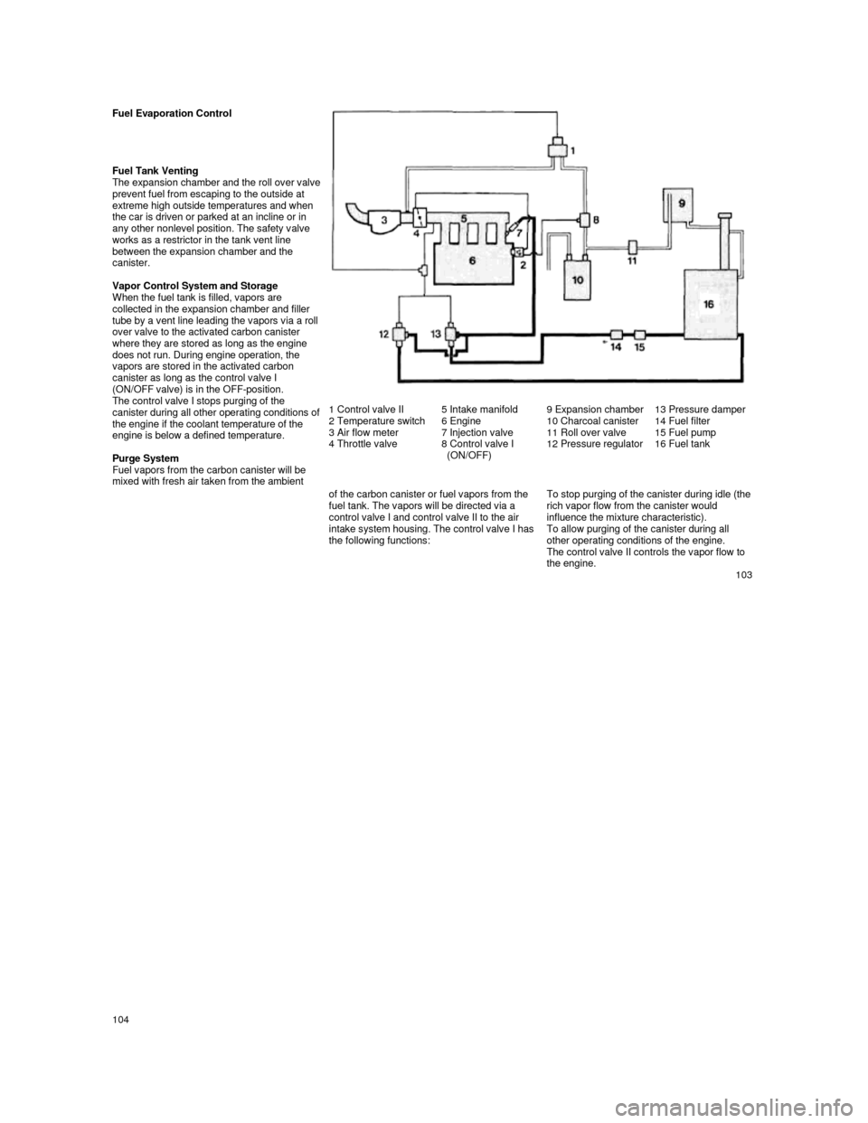
Fuel Evaporation Control
Fuel Tank Venting
The expansion chamber and the roll over valve prevent fuel from escaping to the outside at
extreme high outside temperatures and when
the car is driven or parked at an incline or in
any other nonlevel position. The safety valve
works as a restrictor in the tank vent line between the expansion chamber and the
canister.
Vapor Control System and Storage
When the fuel tank is filled, vapors are
collected in the expansion chamber and filler
tube by a vent l
ine leading the vapors via a roll over valve to the activated carbon canister where they are stored as long as the engine does not run. During engine operation, the
vapors are stored in the activated carbon
canister as long as the control valve I
(ON/OFF valve) is in the OFF-position.
The control valve I stops purging of the
canister during all other operating conditions of the engine if the coolant temperature of the
engine is below a defined temperature.
Purge System
Fuel vapors from the carbon canister will be
mixed with fresh air taken from the ambient
1 Control valve II
2 Temperature switch
3 Air flow meter
4 Throttle valve 5 Intake manifold
6 Engine
7 Injection valve
8 Control valve I
(ON/OFF) 9 Expansion chamber
10 Charcoal canister
11 Roll over valve
12 Pressure regulator
13 Pressure damper 14 Fuel filter
15 Fuel pump
16 Fuel tank
of the carbon canister or fuel vapors from the
fuel tank. The vapors will be directed via a
control valve I and control valve II to the air
intake system housing. The control valve I has the following functions:
To stop purging of the canister during idle (the rich vapor flow from the canister would
influence the mixture characteristic).
To allow purging of the canister during all
other operating conditions of the engine.
The control valve II controls the vapor flow to
the engine.
103
http://www.9ss1.dk/porsche944
104
Page 56 of 66

Engine Design Specifications
Design
Operating cycle
Lubrication
Cylinder block
Cylinder head
Valve operation
Camshaft drive
Crankshaft
Fuel injection 4-cylinder, in-line engine, front mount with two ba
lance-shafts
4-stroke
Pressure oil circulation from oil sump,
full flow filter
Light metal
Light metal
Overhead camshaft
(944 S: 2 overhead camshafts)
Spur belt drive
Forged, 5 main bearings
AFC (Air Flow Control) Power Train
Manual transmission
Gear ratio
1st gear
2nd gear
3rd gear
4th gear
5th gear
Axle ratio Gear ratio 944
3.600:1
2.125:1
1.458:1
1.071:1
0.730:1
3.500:1
3.889:1 Gear ratio 944 S
3.500:1
2.059:1
1.400:1
1.034:1
0.829:1
3.500:1
3.889:1 Gear ratio 944 Turbo
3.500:1
2.059:1
1.400:1
1.034:1
0.829:1
3.500:1
3.375:1
Clutch
Power transmission Single plate dry disc, hydraulically operated
Double constant velocity joints and drive shaft
Automatic transmission 944
Gear ratio 1st gear
2nd gear
3rd gear
Reverse gear
Axle ratio
Clutch 2.714:1
1.500:1
1.000:1
2.429:1
3.455:1
Hydrodynamic torque converter
109
Filling Capacities
Engine oil With filter change approx. 6.34 (Turbo: approx. 6.87) U.S. qts. or 6 (Turbo: approx. 6.5) liters.
Check oil level with dipstick a few minutes after e ngine has stopped. The difference between
the max. and min. marks on the dipstick is approx. 1 U.S. qt. or 1 liter.
Only use brand name oil which has been tested and a pproved by Porsche.
Your authorized Porsche dealer will be glad to advi se you.
Porsche does not recommend the use of oil additives . See also "Engine Oils".
Cooling system with heating
Approx. 8,2 U.S. qts. or 7,8 liters. Factory filled to -31°F (-35°C). Only use phosphate-free
anti-freeze containing ethylene glycol recommended for aluminum engines and radiators.
Manual transmission
Approx. 0.53 U.S. gal. or 2.0 liters. Use hypoid oi l SAE 80 labeled "For Service API/GL4 or
Mil-L 2105".
Automatic transmission with
torque converter Approx. 1.72 U.S. gal. or 6.5 liters ATF Dexron®. At oil c hanges 3 U.S. qts. or 2.8 liters are
required.
Differential of automatic transmission
Approx. 1 U.S. qts. or 1 liter hypoid oil SAE 90 ac cording to API classification GL 5 or
Mil-L 2105 B.
Power steering
Approx. 0.63 U.S. qts. or 0.6 liter ATF Dexron®
Fuel tank Approx. 21.1 U.S. gals, or 80 liters including a re serve of 2.1 U.S. gals, or 8 liters.
Unleaded fuel only! Minimum octane rating 944 91 RO N (87 CLC or AKI ((R+M)/2) rating on fuel
pumps in U.S.A.), 944 S / 944 Turbo 95 RON (90 CLC or AKI ((R+M)/2) rating on fuel pumps in U.S.A.)
Brake fluid Approx. 0.42 U.S. pint or 0.2 liter. Only use brake fluid conforming to specifications
SAE J 1703, DOT 3 or DOT 4.
Windshield and headlight washer system
Approx. 1.59 U.S. gals, or 6.0 liters.
Refrigerant for air conditioning Approx. 33.5 oz or 950 g. Refrigerant R 12 (CCI2F2)
Cooling system mixing chart
(Approximate values)
Anti-freeze-Water
Consult your authorized dealer about
the approved anti-freeze mixtures. Temp, down to
-13° F (-25°C) -23° F (-30° C) -31° F (-35° C)
Anti-freeze
40%
45%
50% Water
60% 55% 50%
Anti-freeze
3.1 liters / 3.3 U.S. qts.3.5 liters / 3.7 U.S. qts.3.9 liters / 4.1 U.S. qts.
Water
4.7 liters / 5.0 U.S. qts.
4.3 liters / 4.5 U.S. qts. 3.9 liters / 4.1 U.S. qts.
110