1987 PORSCHE 944 air conditioning
[x] Cancel search: air conditioningPage 12 of 66

Rear View Mirrors
Do not put decals or other signs on the
windows that may interfere with the driver's
vision.
Adjust the outside and inside mirrors before driving. It is important for safe driving that you have good vision to the rear.
Inside day-night mirror
You can adjust the day-
night mirror from clear daylight visibility to non-glare visibility at night by moving the lever at the bottom of the
mirror forward or rearward.
Heated outside mirrors with remote
control
When you turn on the rear window defogger,
the outside rear view mirror is also heated.
The outside mirrors are ad
justable from inside of the vehicle by a four direction switch
located on the left door and a rocker switch
located on the center console ahead of the
gear selection lever. The rocker switch (A)
selects either the left or right mirror for
adjustment. Push
the rocker switch forward to select the left mirror, and rearward to select
the right mirror. Then the four direction switch
will adjust the selected mirror in any of the four directions.
The mirror housing is hinged and can be
folded flat against the c
ar in either direction to prevent damage in tight parking spots.
If necessary, the outside mirrors can also be
adjusted manually.
22
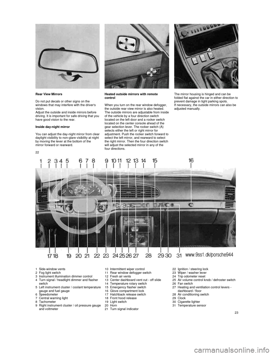
1 Side-window vents 2 Fog light switch
3 Instrument illumination dimmer control
4 Turn signal / headlight dimmer and flasher
switch
5
Left instrument cluster / coolant temperature gauge and fuel gauge
6 Speedometer
7 Central warning light
8 Tachometer
9 Right instrument cluster / oil pressure gauge and voltmeter
10 Intermittent wiper control
11 Rear window defogger switch
12 Fresh air vents
13 Center dashboard vent cut -
off slide14 Temperature rotary switch
15 Emergency flasher switch
16 Glove compartment lock
17 Hatchback release switch
18 Front hood release
19 Light switch
20 Horn
21 Turn signal indicator
22 Ignition / steering lock
23 Wiper / washer lever
24 Trip odometer reset
25
Air volume control knob / defroster switch
26 Fan switch
27 Heating and ventilation control levers -
dashboard / floor
28
Air conditioning switch
29 Clock
30 Cigarette lighter
31 Temperature sensor
23
Page 23 of 66

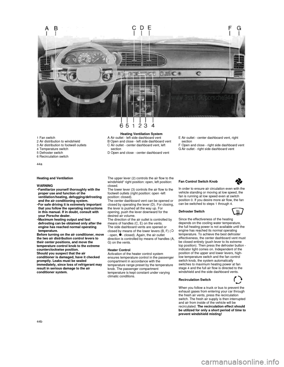
Heating Ventilation System
1 Fan switch
2 Air distribution to windshield
3 Air distribution to footwell outlets
4 Temperature switch
5 Defroster switch
6 Recirculation switch
A Air outlet - left side dashboard vent
B Open and close - left side dashboard vent
C
Air outlet - center dashboard vent, left
section
D Open and close - center dashboard vent
E Air outlet - center dashboard vent, right
section
F
Open and close - right side dashboard vent
G Air outlet - right side dashboard vent
44a
Heating and Ventilation
WARNING
Familiarize yourself thoroughly with the proper use and function of the
ventilation/heating, defogging/defrosting
and the air conditioning system.
For safe driving it is extremely important that you follow the operating instructions
in this manual. If in doubt, consult with
your Porsche dealer.
Maximum heating output and fast defrosting can be obtained only after the
engine has reached normal operating
temperature.
Before turning on the air conditioner, move the two air distribution control levers to
their center positions, and move the
temperature control knob to the extreme
counterclockwise position.
Should you suspect that the air
conditioner is damaged, have it checked
promptly. Leaks must be sealed
immediately, since loss of refrigerant may
result in serious damage to the air
conditioner system.
The upper lever (2) controls the air flow to the windshield" right position: open, left position: closed.
The lower lever (3) controls the air flow to the
footwell outlets (right position: open -left
position: closed).
The center dashboard vent can be opened or
closed by operating the lever (D). For closing,
the lever is pushed all the way up. For
opening, push the lever downward for the
desired air volume.
The direction of the air outlet is controlled by
means of handles (C, E) on the vents.
The side dashboard vents are opened or
closed by means of the lower levers (B, F) (
- open, - closed). Again, the air outlet direction is controlled by means of handles (A, G) on the vents.
Heater Control
Activation of the heater control system ensures temperature control in the passenger
compartment in accordance with the
temperature range preset by the temperature
knob. The passenger compartment
temperature is kept constant under varying
climatic conditions.
Fan Control Switch Knob
In order to ensure air circulation even with the
vehicle standing or moving at low speed, the
fan is running at low speed even at switch
position 0. If you desire more air flow, the fan
can be switched to steps 1 through 4.
Defroster Switch
Since the effectiveness of the heating
depends on the cooling water temperature,
the full heating power is not available until the
engine has reached its normal operating
temperature. To achieve the best defroster
effectiveness, the center dashboard vent must be closed entirely (push lever to its extreme
top position). Then press the defroster button - indicator light comes on. Independent of the
position of the upper and lower levers, high-
low temperature switch and the fan control
switch knob, the system automatically
switches to maximum heating power at fan
stage 4 and the full air flow is directed to the
windshield and the side dashboard vents.
Recirculation Switch
When you follow a truck or bus to prevent the
exhaust gases from entering your car through
the fresh air vents, press the recirculation
switch. The fresh air supply is then interrupted and air from inside of the vehicle will be
recirculated. The recirculation effect should
be utilized for only a short period of time to prevent windshield misting! 44b
Page 24 of 66

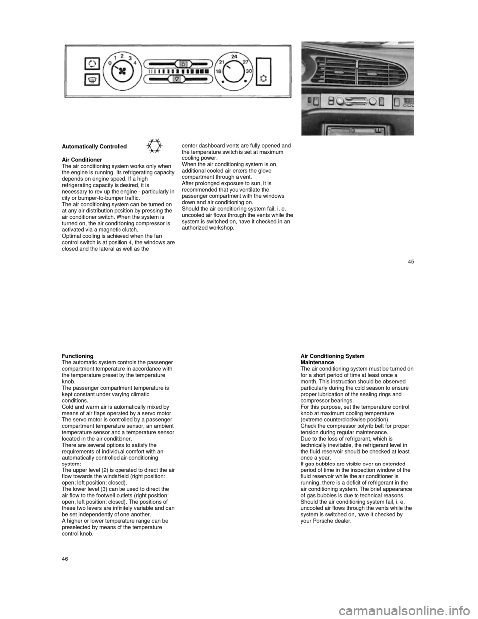
Automatically Controlled
Air Conditioner
The air conditioning system works only when
the engine is running. Its refrigerating capacity depends on engine speed. If a high
refrigerating capacity is desired, it is
necessary to rev up the engine -
particularly in city or bumper-to-bumper traffic.
The air conditioning system can be turned on
at any air distribution position by pressing the
air conditioner switch. When the system is
turned on, the air conditioning compressor is
activated via a magnetic clutch.
Optimal cooling is achieved when the fan
control switch is at position 4, the windows are closed and the lateral as well as the
center dashboard vents are fully opened and
the temperature switch is set at maximum
cooling power.
When the air conditioning system is on,
additional cooled air enters the glove
compartment through a vent.
After prolonged exposure to sun, it is recommended that you ventilate the
passenger compartment with the windows
down and air conditioning on.
Should the air conditioning system fail, i. e.
uncooled air flows through the vents while the
system is switched on, have it checked in an
authorized workshop.
45
Functioning
The automatic system controls the passenger
compartment temperature in accordance with
the temperature preset by the temperature
knob.
The passenger compartment temperature is
kept constant under varying climatic
conditions.
Cold and warm air is automatically mixed by
means of air flaps operated by a servo motor.
The servo motor is controlled by a passenger
compartment temperature sensor, an ambient
temperature sensor and a temperature sensor located in the air conditioner.
There are several options to satisfy the
requirements of individual comfort with an
automatically controlled air-conditioning
system:
The upper level (2) is operated to direct the air flow towards the windshield (right position:
open; left position: closed).
The lower level (3) can be used to direct the
air flow to the footwell outlets (right position:
open; left position: closed). The positions of
these two levers are infinitely variable and can be set independently of one another. A higher or lower temperature range can be preselected by means of the temperature
control knob.
Air Conditioning System Maintenance The air conditioning system must be turned on for a short period of time at least once a
month. This instruction should be observed
particularly during the cold season to ensure
proper lubrication of the sealing rings and
compressor bearings.
For this purpose, set the temperature control
knob at maximum cooling temperature
(extreme counterclockwise position).
Check the compressor polyrib belt for proper
tension during regular maintenance.
Due to the loss of refrigerant, which is
technically inevitable, the refrigerant level in
the fluid reservoir should be checked at least
once a year.
If gas bubbles are visible over an extended
period of time in the inspection window of the
fluid reservoir while the air conditioner is
running, there is a deficit of refrigerant in the
air conditioning system. The brief appearance
of gas bubbles is due to technical reasons.
Should the air conditioning system fail, i. e.
uncooled air flows through the vents while the
system is switched on, have it checked by
your Porsche dealer.
46
Page 56 of 66

Engine Design Specifications
Design
Operating cycle
Lubrication
Cylinder block
Cylinder head
Valve operation
Camshaft drive
Crankshaft
Fuel injection 4-cylinder, in-line engine, front mount with two ba
lance-shafts
4-stroke
Pressure oil circulation from oil sump,
full flow filter
Light metal
Light metal
Overhead camshaft
(944 S: 2 overhead camshafts)
Spur belt drive
Forged, 5 main bearings
AFC (Air Flow Control) Power Train
Manual transmission
Gear ratio
1st gear
2nd gear
3rd gear
4th gear
5th gear
Axle ratio Gear ratio 944
3.600:1
2.125:1
1.458:1
1.071:1
0.730:1
3.500:1
3.889:1 Gear ratio 944 S
3.500:1
2.059:1
1.400:1
1.034:1
0.829:1
3.500:1
3.889:1 Gear ratio 944 Turbo
3.500:1
2.059:1
1.400:1
1.034:1
0.829:1
3.500:1
3.375:1
Clutch
Power transmission Single plate dry disc, hydraulically operated
Double constant velocity joints and drive shaft
Automatic transmission 944
Gear ratio 1st gear
2nd gear
3rd gear
Reverse gear
Axle ratio
Clutch 2.714:1
1.500:1
1.000:1
2.429:1
3.455:1
Hydrodynamic torque converter
109
Filling Capacities
Engine oil With filter change approx. 6.34 (Turbo: approx. 6.87) U.S. qts. or 6 (Turbo: approx. 6.5) liters.
Check oil level with dipstick a few minutes after e ngine has stopped. The difference between
the max. and min. marks on the dipstick is approx. 1 U.S. qt. or 1 liter.
Only use brand name oil which has been tested and a pproved by Porsche.
Your authorized Porsche dealer will be glad to advi se you.
Porsche does not recommend the use of oil additives . See also "Engine Oils".
Cooling system with heating
Approx. 8,2 U.S. qts. or 7,8 liters. Factory filled to -31°F (-35°C). Only use phosphate-free
anti-freeze containing ethylene glycol recommended for aluminum engines and radiators.
Manual transmission
Approx. 0.53 U.S. gal. or 2.0 liters. Use hypoid oi l SAE 80 labeled "For Service API/GL4 or
Mil-L 2105".
Automatic transmission with
torque converter Approx. 1.72 U.S. gal. or 6.5 liters ATF Dexron®. At oil c hanges 3 U.S. qts. or 2.8 liters are
required.
Differential of automatic transmission
Approx. 1 U.S. qts. or 1 liter hypoid oil SAE 90 ac cording to API classification GL 5 or
Mil-L 2105 B.
Power steering
Approx. 0.63 U.S. qts. or 0.6 liter ATF Dexron®
Fuel tank Approx. 21.1 U.S. gals, or 80 liters including a re serve of 2.1 U.S. gals, or 8 liters.
Unleaded fuel only! Minimum octane rating 944 91 RO N (87 CLC or AKI ((R+M)/2) rating on fuel
pumps in U.S.A.), 944 S / 944 Turbo 95 RON (90 CLC or AKI ((R+M)/2) rating on fuel pumps in U.S.A.)
Brake fluid Approx. 0.42 U.S. pint or 0.2 liter. Only use brake fluid conforming to specifications
SAE J 1703, DOT 3 or DOT 4.
Windshield and headlight washer system
Approx. 1.59 U.S. gals, or 6.0 liters.
Refrigerant for air conditioning Approx. 33.5 oz or 950 g. Refrigerant R 12 (CCI2F2)
Cooling system mixing chart
(Approximate values)
Anti-freeze-Water
Consult your authorized dealer about
the approved anti-freeze mixtures. Temp, down to
-13° F (-25°C) -23° F (-30° C) -31° F (-35° C)
Anti-freeze
40%
45%
50% Water
60% 55% 50%
Anti-freeze
3.1 liters / 3.3 U.S. qts.3.5 liters / 3.7 U.S. qts.3.9 liters / 4.1 U.S. qts.
Water
4.7 liters / 5.0 U.S. qts.
4.3 liters / 4.5 U.S. qts. 3.9 liters / 4.1 U.S. qts.
110