Page 104 of 284
8-84 CHARGING SYSTEM - Alternator
REMOVAL AND INSTALLATION (Vehicles with Air Conditioner)
30-35 Nm
20-22 Nm
14-16 ft.lbs. D Draining of Refrigerant (Refer to
CONDITIONING - Service Adjust-
1 ‘ost-installation Operation
1 Charging of Refrigerant (Refer to
GROUP 24 HEATERS AND AIR
CONDITIONING - Service Adjust-
ment Procedures)
D Adjustment of Drive Belt Tension
(Refer to GROUP 7 COOLING and
GROUP 24 HEATERS AND AIR
CONDITIONING ~ Service Adjust-
ment Procedures)
:emoval steps
1. Connection of high pressure hose
2. Connection of low pressure hose
3. Connection of compressor connector
4. Compressor
5. Connection of alternator connector
~~ 6. Alternator
OTE
) Reverse the removal procedures to reinstall.
I) e+ : Refer to “Service Points of installation” 16W1566
/ STB Revision
Page 105 of 284
CHARGING SYSTEM - Alternator 8-85
SERVICE POINTS OF INSTALLATION
6. INSTALLATION OF ALTERNATOR
(1) Position the alternator and insert the support bolt. (Do not
attach the nut.)
(2) Push the alternator forward and determine how many
spacers [thickness: 0.198 mm (.0078 in.)] should be
inserted between the front leg of the alternator and the
front case (space A in the illustration). (There should be
enough spacers so that they do not fall out when you let
go of them.)
(3) Insert the spacers (space A in the illustration), attach the
nut, and complete the installation.
; ‘.-:,
i
) STB Revision
Page 106 of 284
CHARGING SYSTEM-Alternator
10 11 14
8 ? \I I
Disassembly steps
4* 1. Pulley
2. Seal
l a 3. Rotor assembly
4. Rear bearing
5. Bearing retainer
6. Front bearing
4*
7. Front bracket
8. Stator
9. Terminal
10. Plate
4* 11. Regulator and brush holder
12. Brush
13. Brush spring
14. Slinger
15. Rectifier assembly
4, 16. Rear bracket NOTE
(1) Reverse the disassembly procedures to reassemble.
(2) +e : Refer to “Service Points of Disassembly”.
(3) l
+ : Refer to “Service Points of Reassembly”.
1 EL666 1 STB Revision
Page 107 of 284

CHARGING SYSTEM-Alternator 8-87
6ELllt
SERVICE POINTS OF DISASSEMBLY
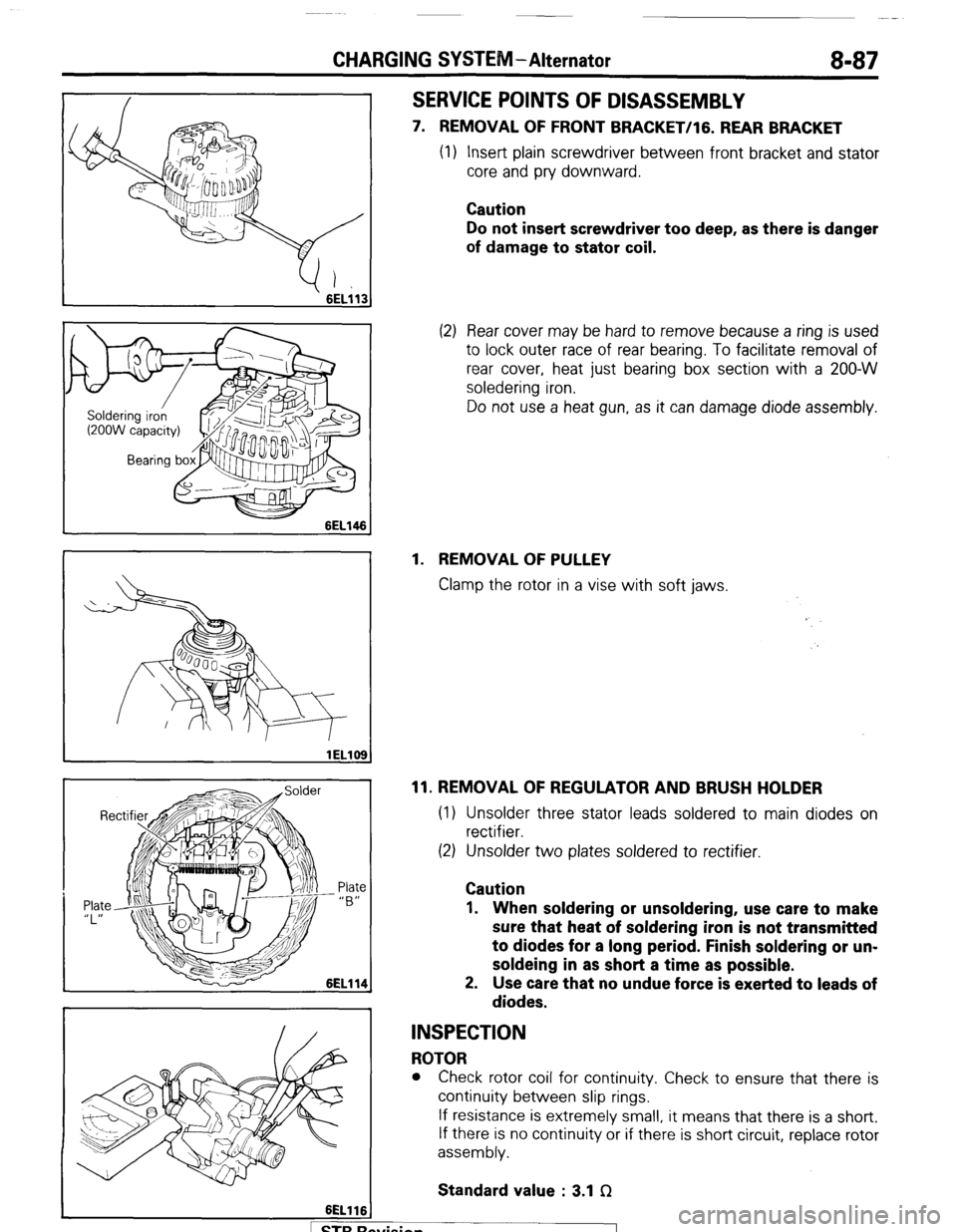
7. REMOVAL OF FRONT BRACKET/lG. REAR BRACKET
(1) Insert plain screwdriver between front bracket and stator
core and pry downward.
Caution
Do not insert screwdriver too deep, as there is danger
of damage to stator coil.
(2) Rear cover may be hard to remove because a ring is used
to lock outer race of rear bearing. To facilitate removal of
rear cover, heat just bearing box section with a 200-W
soledering iron.
Do not use a heat gun, as it can damage diode assembly.
1. REMOVAL OF PULLEY
Clamp the rotor in a vise with soft jaws.
11. REMOVAL OF REGULATOR AND BRUSH HOLDER
(1) Unsolder three stator leads soldered to main diodes on
rectifier.
(2) Unsolder two plates soldered to rectifier.
Caution
1. When soldering or unsoldering, use care to make
sure that heat of soldering iron is not transmitted
to diodes for a long period. Finish soldering or un-
soldeing in as short a time as possible.
2. Use care that no undue force is exerted to leads of
diodes.
INSPECTION
ROTOR
l Check rotor coil for continuity. Check to ensure that there is
continuity between slip rings.
If resistance is extremely small, it means that there is a short.
If there is no continuity or if there is short circuit, replace rotor
assembly.
Standard value : 3.1 f2
. . .
I 1 STB hewsion
Page 108 of 284

8-88 CHARGING SYSTEM-Alternator
6EL115
3ELOlO
lELll0
lELll1
A
) STBRc
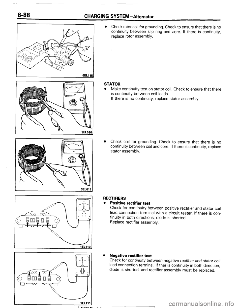
l Check rotor coil for grounding. Check to ensure that there is no
continuity between slip ring and core. If there is continuity,
replace rotor assembly.
STATOR
l Make continuity test on stator coil. Check to ensure that there
is continuity between coil leads.
If there is no continuity, replace stator assembly.
l Check coil for grounding. Check to ensure that there is no
continuity between coil and core. If there is continuity, replace
stator assembly.
RECTIFIERS
l Positive rectifier test
Check for continuity between positive rectifier and stator coil
lead connection terminal with a circuit tester. If there is con-
tinuity in both directions, diode is shorted.
Replace rectifier assembly.
l Negative rectifier test
Check for continuity between negative rectifier and stator coil
lead connection terminal. If ther is continuity in both direction,
diode is shorted, and rectifier assembly must be replaced.
evision
-7
Page 109 of 284
CHARGING SYSPE 8-89
lELll2
,
l Diode trio test
Check three diodes for continuity by connecting a circuit tester
to both ends of each diode. If there is no continuity or no
continuity in both directions, diode is defective and heatsink
assembly must be replaced.
REPLACEMENT OF BRUSH
A brush worn away to the limit is replaced using the procedure
below.
(1) Remove the pigtail solder and take out the old brush and
spring.
(2) Install brush spring and new brush in brush holder.
(3) Insert the brush to where there is a space 2-3 mm
(.079-,118 in.) between the limit line and the end of the brush
holder.
(4) While maintaining the position of the step, solder the pigtails
to the end of the brush holder.
1 STB Revision
1
Page 110 of 284
8-90 CHARGING SYSTEM-Alternator
Rear bracket Wire
6EL122
6EL123 I
SERVICE POINTS OF REASSEMBLY
3. REASSEMBLY OF ROTOR ASSEMBLY
Perform reassembly in reverse procedure of disassembly,
Before
rotor is attached to rear bracket, insert wire through
small hole made in rear bracket to lift brush. After rotor has
6een installed, remove the wire.
STB Revision
Page 143 of 284

METERS AND GAUGES-Specifications
METERS AND GAUGES
8-123
SPECIFICATIONS
GENERAL SPECIFICATIONS
METERS AND GAUGES NOEHB-
Items
Speedometer
Type
Tachometer
Type
Detection source
Fuel gauge
Type
Fuel gauge unit
Type
Water temperature gauge
Type
Water temperature gauge unit
Type
Oil pressure gauge
Type
Oil pressure gauge unit
Type
Inclinometer
Type
Damping system
Voltage meter
Type Specifications
Electromagnetic type
Pulse type
Ignition coil
Bimetal type (constant-voltage relay incorporated for 7V)
Variable resistance type
Bimetal type (7V operation)
Thermistor type
Bimetal type
Bimetal type
Gravity type
Oil-filled system
Bimetal type
INDICATOR AND WARNING LIGHTS
NOEHC-B
Items Specifications
Turn signal indicator lights
W 1.4 (74)
High beam indicator light W 1.4 (74)
Door-ajar warning light W 1.4 (74)
Fasten seat belt indicator light W 1.4 (74)
Brake warning light W 1.4 (74)
Charging warning light W 1.4 (74)
4WD indicator light W 1.4 (74)
EGR warning light W 1.4 (74)
Oil pressure warning light W 1.4 (74)
A/T oil temperature warning light
W 1.4 (74)
Overdrive indicator light
W 1.4 (74)
Free-wheeling hub indicator light W 1.4 (74)
NOTE
The values in parentheses denote SAE grade numbers.
1 STB Revision ”