Page 45 of 284

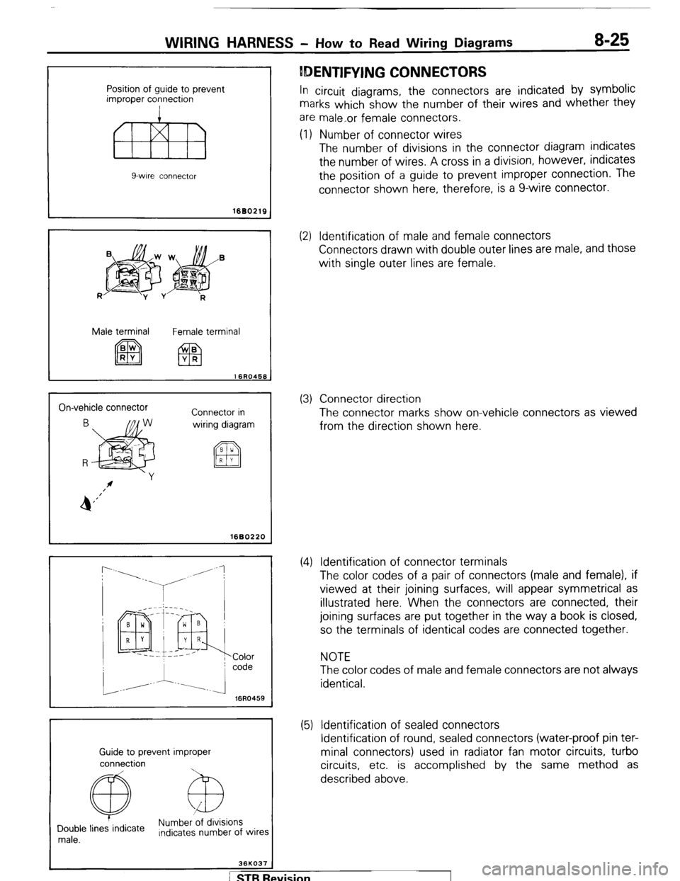
Position of guide to prevent
improper connection
fl!liB
9-wire connector
WIRING HARNESS - How to Read Wiring Diagrams 8-25
IDENTIFYING CONNECTORS
In circuit diagrams, the connectors are indicated by symbolic
marks which show the number of their wires and whether they
are male,or female connectors.
(1) Number of connector wires
The number of divisions in the connector diagram indicates
the number of wires. A cross in a division, however, indicates
the position of a guide to prevent improper connection. The
connector shown here, therefore, is a g-wire connector.
1680219
R
jpg$&’
-y v
R
Male terminal
Female terminal
On-vehicle connector
Connector in
wiring diagram
I 1680220
r
16R0459
Guide to prevent improper
connection
@ Numb&ions
Double lines indicate
male. Indicates number of wires
36KO37
(2) Identification of male and female connectors
Connectors drawn with double outer lines are male, and those
with single outer lines are female.
(3) Connector direction
The connector marks show on-vehicle connectors as viewed
from the direction shown here.
(4) Identification of connector terminals
The color codes of a pair of connectors (male and female), if
viewed at their joining surfaces, will appear symmetrical as
illustrated here. When the connectors are connected, their
joining surfaces are put together in the way a book is closed,
so the terminals of identical codes are connected together.
NOTE
The color codes of male and female connectors are not always
identical.
(5) Identification of sealed connectors
Identification of round, sealed connectors (water-proof pin ter-
minal connectors) used in radiator fan motor circuits, turbo
circuits, etc. is accomplished by the same method as
described above.
/ STB Revision
Page 46 of 284
8-26 WIRING HARNESS - HOW to Read Wiring Diagrams
SYMBOLIC MARKS
Various equipment is indicated symbolically in circuit idiagrams as shown below.
Battery Body ground Single bulb Resistor Diode Capacitor
Fuse Equipment ground
Fusible link
Motor
Speaker Coil ~
4 Transistor Crossing of lines
4 -1~ with conron
WIRE COLOR CODES Wire colors are identified by the following color codes.
Example: 1.25 - GB Code Wire color Code Wire color
B
Br Black
Brown LI
0 Light blue
Oranqe
I P
i 1 Gr 1 Grav 1 R 1 Red I
I L I Blue
I Y I Yellow I
L 1.25: Wire size (mm2)
F: Flexible wire
T: Twisted wire
(1) No code indicates 0.5 mm2(.0008 in.*).
(2) Cable color-code in parantheses indicates
0.3 mm* (.0005 in.‘).
Lg Light green W White
NOTE
If a cable has two colors, the first of the two color code characters
indicates the basic color (color of the cable coating) and the sec-
ond indicates the marking color.
STB Revision
Page 47 of 284
WIRING HARNESS - Overall Wiring Diagram 8-27
OVERALL WIRING DIAGRAM
NOBDC-‘3
) STB Revision
Page 96 of 284
8-76 CHARGING SYSTEM - Circuit Diagram
3 CHARGING CIRCUIT
Battery Ignition switch
OFF
Main
m fusible ’ L
link
A-02
fl.3-Br 1~5~~
, A-23 Sub fusible link
(IGN . SW)
IAM IG ] c-55
3
3
A m
A
To turn signal flasher
unit [Refer to P.8-49.1 Multi-
n, Irnn4P
ComSeter
Remark
For information concerning the ground points (example:
q ),
refer to P.8-7. 37W605
Wiring color code
B: Black Br: Brown G: Green Gr: Gray L: Blue Lg: Light green
LI: Light blue 0: Orange P: Pink R: Red Y: Yellow W: White
1 STB Revision
Page 115 of 284
STARTING SYSTEM - Circuit Diagram 8-95
1 STARTING CIRCUIT
(VEHICLES WITH A MANUAL TRANSMISSION)
11171 w
$in fusible
START
I k
9
OFF
ON ACC
ST
c-55
.I
m I BY
Sub fusible link Ignition switch
Starter
37W626 / STB Revision
Page 116 of 284
8-96 STARTING SYSTEM - Circuit Diagram
(VEHICLES WITH AN AUTOMATIC TRANSMISSION)
I
Sub fusible link
A-23 (IGN . SW)
_ 5-WI-754 1
0.5-G 1, 1,
L-l m 1 L-W
Battery Ignition switch
c-47
2-BY-Z-BY*2
N P
!-BY Z-BY1 (Z-BY*]
L-l
R BY BY
“I “2
Remark
For information concerning the ground points (example:
q ),
refer to P.8-7.
Wiring color code
B: Black
Br: Brown
G: Green
Gr: Gray L: Blue
LI: Light blue
0: Orange P: Pink Lg: Light green
R: Red
Y: Yellow
W: White
STB Revision
Page 130 of 284
8-110 IGNITION SYSTEM - Circuit Diagram
2 IGNITDN CIRCUIT
Sub fusible link
A-23
(IGN - SW) Ignition switch
5-wn5-w-
0.5-G 1
u
63- Z-W
I
IAT
Main 1
fusible
Rnttprv link
m
ze 3 cj _-’ A:“p m
N CL
I 64-b I I I m
I
Ei
I
L Disi
To combination meter d A-an b
(TACHO)
[Refer to P.8-52.1
I I Ignition coil
37 w009
Remaik
-‘For information concerning the ground points (example: q ),
refer to P.8-7.
Wiring color code’ c
B: Black Br: Brown G: Green Gr: Gray L: Blue Lg: Light green
LI: Light blue 0: Orange P: Pink R: Red Y: Yellow V/: White
1 STB Revision 1
Page 148 of 284
8-128 METERS AND GAUGES - Circuit Diagram
CIRCUIT DIAGRAM
METER CIRCUIT
Ignition switch
q [Refer to
To turn-signal switch
[Refer to P.8-491
I
To seat belt timer
[Refer to P.8-661 P.8-511 -
To seat belt warning
buzzer [Refer to P.8-661
1.25-GBA
, ^.
To alternator 48,5!W III -1 / 1 , 1 '----f--d+ii$$j IRefer to P.8.371 D I
.I_ -0 dimmkr, passinq
‘I+,:’ ! I I I II -I
I r I I I II YI
;witch and light control y K
clay [Refer to P.8-461
To dome liaht 5--hIIII I
----m-w-
[Refer to P&47] -w
Combination meter
( STB Revision