Page 1132 of 1865

7C TROUBLESHOOTING
STEP 4 (ROAD TEST)
This step is performed to check for problems in the various ranges. If these tests show any problems,
adjust or replace by referring to the QUICK DIAGNOSIS CHART and mechanical sections.
Caution
Perform the test at normal ATF operating temperature (50—80°C, 122—176°F).
Gearshift Function Check Items
1. Shift shock must be minimal, and shifting must be smooth.
2. Engine speed must not run away, and the shifting must not be delayed.
3. Transaxle must shift through Di D2 -»• D3 in D range.
4. Transaxle must shift from 3rd in D range to 2nd gear when 2 range is selected.
5. Transaxle must shift from 2nd to 1st when 1 range is selected from 3rd gear in D range.
6. Transaxle must not upshift in 1 range.
7. Transaxle must remain in 2nd gear in 2 range.
8. Transaxle must positively lock in P range.
The transaxle must positively lock when P range is selected while moving at a speed below 4 km/h
(2.5 mph) on level ground. The transaxle must positively lock when set in P range with the vehicle
on a gentle slope and the brakes disengaged.
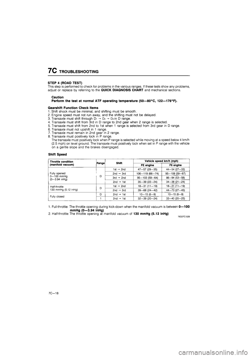
Shift Speed
Throttle condition
(manifold vacuum) Hange Shift Vehicle speed km/h (mph) Throttle condition
(manifold vacuum) Hange Shift FE engine F6 engine
Fully opened 0—100 mmHg (0-3.94 inHg)
D
1st - 2nd 47—57 (29—35) 44-54 (27-33)
Fully opened 0—100 mmHg (0-3.94 inHg)
D 2nd - 3rd 106-119 (66—74) 95-108 (59-67) Fully opened 0—100 mmHg (0-3.94 inHg)
D 3rd - 2nd 95-103 (59-64) 86-94 (53-58)
Fully opened 0—100 mmHg (0-3.94 inHg)
D
2nd - 1st 35-39 (22-24) 34-38 (21-24)
Half-throttle 130 mmHg (5.12 inHg) D 1st - 2nd 18-31 (11-19) 18-31 (11-19) Half-throttle 130 mmHg (5.12 inHg) D 2nd -»• 3rd 39-68 (24—42) 44-73 (27-45)
Fully closed D 2nd - 1st 10-15 (6-9) 10-15 (6-9) Fully closed 1 2nd - 1st 32—39 (20-24) 33-40 (20-25)
1. Full-throttle: The throttle opening during kick-down when the manifold vacuum is between 0—100
mmHg (0—3.94 inHg)
2. Half-throttle: The throttle opening at manifold vacuum of 130 mmHg (5.12 inHg) 76G07C-028
7C-18
Page 1133 of 1865
TROUBLESHOOTING 7C
Basic Gearshift Pattern
FE engine
mm Hg
(in Hg)
0 (0)
CO
40 (1.6)
100
(3.9)
200
(7.9) E 3 3 O CO
V 300 o (11.8)
400-(15.7)
Di«fD2 Di-fhD2
Di<-D2 I I
D1-D2
20 (12)
. Kick-down i D2^-p3 Daf-Da range
100 (62) 120 (74)
Vehicle speed km/h (mph)
F6 engine
mm Hg
(in Hg)
0
(0)
40 (1.6)
100 (3.9)
CD 3 c/> CO d>
E 3 3 o CD >
o H— "c co
200 (7.9)
300 (11.8)
400 (15.7)
Dl<-D2
DI^DZ DIT*DZ Kick-down Da 4
Da
Dzj+Da range
40 (25) 60 (37) 80 (50) 100 (62) 120 (74)
Vehicle speed km/h (mph)
76G07C-029
7C—19
Page 1134 of 1865
7C TROUBLESHOOTING
STEP 5 (OIL PRESSURE TEST)
This step determines line pressure, and governor pressure to check the hydraulic components and
for oil leakage.
Line Pressure Test
Preparation
1. Connect the SST to the line pressure output point.
2. Connect a tachometer to the engine.
3. Follow the test preparation procedure show in STEP 2 (STALL TEST).
Procedure
76G07C-030
1. Start the engine and verify that the idle speed is 950-5° rpm.
2. Shift the selector lever to D range.
3. Read the line pressure at idle.
4. Depress the brake pedal firmly with the left foot, and gradually depress the accelerator pedal with
the right foot.
5. Read the line pressure as soon as the engine speed becomes constant; then release the accelera-
tor pedal.
Caution
Steps 4 to 5 must be done within 5 seconds.
5. Shift the selector lever to N range and let the engine idle for one minute or more.
6. Read the line pressure at idle and engine stall speeds for each range in the same manner.
7C—20
Page 1137 of 1865

ELECTRIC COMPONENTS 7C
76G07C-036
76G07C-037
76G07C-038
ELECTRIC COMPONENTS
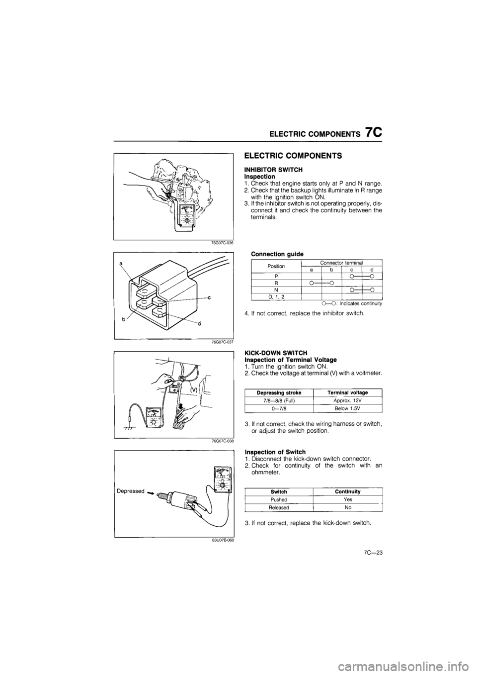
INHIBITOR SWITCH
Inspection
1. Check that engine starts only at P and N range.
2. Check that the backup lights illuminate in R range
with the ignition switch ON.
3. If the inhibitor switch is not operating properly, dis-
connect it and check the continuity between the
terminals.
Connection guide
Position
N
D, 1, 2
Connector terminal
-O
O -O
-O
O—O: Indicates continuity
4. If not correct, replace the inhibitor switch.
KICK-DOWN SWITCH
Inspection of Terminal Voltage
1. Turn the ignition switch ON.
2. Check the voltage at terminal (V) with a voltmeter.
Depressing stroke Terminal voltage
7/8-8/8 (Full) Approx. 12 V
0-7/8 Below 1,5V
3. If not correct, check the wiring harness or switch,
or adjust the switch position.
Inspection of Switch
1. Disconnect the kick-down switch connector.
2. Check for continuity of the switch with an
ohmmeter.
Switch Continuity
Pushed Yes
Released No
3. If not correct, replace the kick-down switch.
83U07B-060
7C—23
Page 1139 of 1865
ON-VEHICLE MAINTENANCE 7C
ON-VEHICLE MAINTENANCE
AUTOMATIC TRANSAXLE FLUID (ATF)
Inspection for Fluid Leaks
Check for fluid leaks; the following figure shows the locations where fluid leakage may possibly occur.
1. Kick-down solenoid
2. Vacuum diaphragm
3. Manual shaft
4. Speedometer driven gear
5. Oil level tube
6. Governor cover
7. Governor
8. Oil pan
9. Oil pump
10. Inhibitor switch
11. Transaxle case
12. Oil pump
13. Square head plugs
14. Bearing cover
15. Drive shaft
76G07C-041
©
i
©
[JdQ©
I
Inspection of Level
1. Apply the parking brake and block the wheels to
prevent the vehicle from rolling.
Note
Place the car on a flat, level surface.
2. Run the engine so that the automatic transaxle fluid
reaches operating temperature.
3. While the engine is idling, shift the select lever from
P to 1 and back again.
4. Let the engine idle.
5.Shift the select lever to P.
76G07C-042
7C-25
Page 1143 of 1865

ON-VEHICLE MAINTENANCE 7C
9. Install the under cover and side cover.
10. Lower the vehicle.
11. Add ATF, and with the engine idling, check the fluid
level.
12. Verify that there is no fluid leakage from the trans-
axle. (Refer to page 7C—25.)
76G07C-052
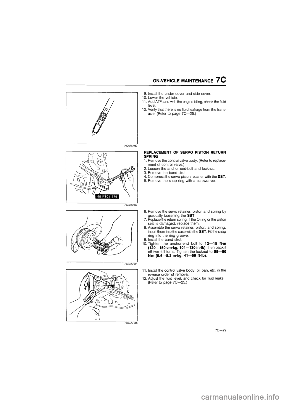
REPLACEMENT OF SERVO PISTON RETURN
SPRING
1. Remove the control valve body. (Refer to replace-
ment of control valve.)
2. Loosen the anchor end-bolt and locknut.
3. Remove the band strut.
4. Compress the servo piston retainer with the SST.
5. Remove the snap ring with a screwdriver.
76G07C-053
76G07C-054
6. Remove the servo retainer, piston and spring by
gradually loosening the SST.
7. Replace the return spring. If the O-ring or the piston
seal is damaged, replace them.
8. Assemble the servo retainer, piston, and spring,
insert them into the case with the SST. Fit the snap
ring into the ring groove.
9. Install the band strut.
10. Tighten the anchor-end bolt to 12—15 N-m
(120—150 cm-kg, 104—130 in-lb), then back it
off two full turns. Tighten the locknut to 55—80
N m (5.6—8.2 m-kg, 41—59 ft-lb).
11. Install the control valve body, oil pan, etc. in the
reverse order of removal.
12. Adjust the fluid level, and check for fluid leaks.
(Refer to page 7C—25.)
76G07C-055
7C—29
Page 1144 of 1865
7C REMOVAL
REMOVAL
PREPARATION
(1) Drain the ATF before removal.
(2) Attach the engine support.
(3) Jack up the vehicle and support it with safety stands.
Components
1. Battery
2. Battery carrier
3. Fresh air duct
4. Main fuse block
5. Distributor leads
6. Speedometer cable
7. Cnnectors
8. Ground wires
9. Selector cable
10. Vacuum hose
11. Front wheels
12. Splash shields
13. Oil cooler outlet and inlet
hoses
14. Tie-rod ends
15. Stabilizer bar control links
16. Lower arm ball joints
17. Driveshaft
18. Joint shaft bracket
76G07C-056
19. Joint shaft and driveshaft
20. Under cover
21. Torque converter bolts
22. Starter
23. Engine mount No.4
24. Engine mount No.2
25. Crossmember and left side
lower arm
26. Transaxle
7C-30
Page 1147 of 1865
REMOVAL 7C
22. Remove the under cover.
23. Remove the torque converter bolts.
76GQ7C-065
24. Remove the starter.
76G07C-066
25. Suspend the engine with the SST.
76G07C-067
26. Remove engine mount No.4 and bracket.
76G07C-068
7C-33